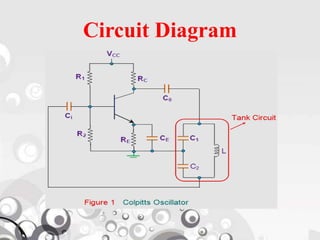
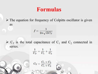
North Western University, Khulna
Electronic Device - III
Course Code : EEE-2301
Presentation Topic : Colpitts Oscillator
Presented by :
20183025021- Md. Milan Molla
20183026021- Md. Mozammel Haque
20183029021- Madan Mohon Debnath
20183030021- Shagar Chowdhury
20183031021- Md. Abdur Rakib
Colpitts Oscillator
Colpitts oscillator is an amplifier with the positive
feedback and it converts DC input signal
into AC output waveform with certain variable frequency
drive and certain shape of
output waveform (like sine wave or square wave, etc) by
using the positive feedback
instead of input signal. Oscillators which utilizes the
inductor L and capacitor C in their circuit are called as LC
oscillator which is a type of linear oscillator.
Colpitts Oscillator Theory
 It consists of a tank circuit which is an LC resonance sub
circuit made of two series capacitors connected in parallel
to an inductor and frequency of oscillations can be
determined by using the values of these capacitors and
inductor of the tank circuit.
 This oscillator is almost similar to Hartley oscillator.
 It is termed as electrical dual of Hartley oscillator and is
designed for the generation of high frequency sinusoidal
oscillations with the radio frequencies typically ranging
from 10 KHz to 300MHz.
 The major difference between these two oscillators is that
it uses tapped capacitance, whereas the Hartley oscillator
uses tapped inductance.
Circuit Diagram
Circuit Explanation
 The capacitor CE connected in the circuit which is
parallel to the RE, provides low reactive path to the
amplified AC signal acting as Bypass capacitor.
 The Resistors R1 and R2 form voltage divider for circuit
and provide bias to the transistor.
 The circuit consists of a RC coupled amplifier with
common emitter configuration transistor.
 The coupling capacitor Coutblocks DC by providing an
AC path from the collector to the tank circuit.
Colpitts Oscillator Working Principle
 Whenever power supply is switched on, the capacitors C1
and C2 start charging and after the capacitors get fully
charged, the capacitors starts discharging through the
inductor L1 in the circuit causing damped harmonic
oscillations in the tank circuit.
 Thus, an AC voltage is produced across C1 & C2 by the
oscillatory current in the tank circuit.
 While these capacitors get fully discharged, the
electrostatic energy stored in the capacitors get transferred
in the form of magnetic flux to the inductor and thus
inductor gets charged.
Working Principle (continue…)
 Similarly, when the inductor starts discharging, the
capacitors start charging again and this process of energy
charging and discharging capacitors and inductor
continues causing the generation of oscillations and the
frequency of these oscillations can be determined by
using the resonant frequency of the tank circuit consisting
of inductor and capacitors.
 This tank circuit is considered as the energy reservoir or
energy storage. This is because of frequent energy
charging and discharging of the inductor, capacitors that
part of LC network forming the tank circuit.
 The continuous undamped oscillations can be obtained
from the Barkhausen criterion.
Working Principle (continue…)
For sustained oscillations, the total phase shift must
be 360º or 0º.
In the above circuit as two capacitors C1 & C2 are
center tapped and grounded, the voltage across
capacitor C2 (feedback voltage) is 180º with the
voltage across capacitor C1 (output voltage).
 The common emitter transistor produces 180º
phase shift between the input and output voltage.
Thus, from the Barkhausen criterion we can get
undamped continuous oscillations.
Formulas
 The equation for frequency of Colpitts oscillator is given
as
 CT is the total capacitance of C1 and C2 connected in
series.
Advantages
 Colpitts oscillator can generate sinusoidal signals of very
high frequencies.
 It can withstand high and low temperatures.
 The frequency stability is high.
 Frequency can be varied by using both the variable
capacitors.
 Less number of components are sufficient.
 The amplitude of the output remains constant over a fixed
frequency range.
Applications
 Colpitts oscillator can be used as High frequency
sinewave generator.
 This can be used as a temperature sensor with some
associated circuitry.
 Mostly used as a local oscillator in radio receivers.
 It is also used as R.F. Oscillator.
 It is also used in Mobile applications.
 It has got many other commercial applications.
Colpitts oscillator

Colpitts oscillator

  • 1.
    North Western University,Khulna Electronic Device - III Course Code : EEE-2301 Presentation Topic : Colpitts Oscillator Presented by : 20183025021- Md. Milan Molla 20183026021- Md. Mozammel Haque 20183029021- Madan Mohon Debnath 20183030021- Shagar Chowdhury 20183031021- Md. Abdur Rakib
  • 2.
    Colpitts Oscillator Colpitts oscillatoris an amplifier with the positive feedback and it converts DC input signal into AC output waveform with certain variable frequency drive and certain shape of output waveform (like sine wave or square wave, etc) by using the positive feedback instead of input signal. Oscillators which utilizes the inductor L and capacitor C in their circuit are called as LC oscillator which is a type of linear oscillator.
  • 3.
    Colpitts Oscillator Theory It consists of a tank circuit which is an LC resonance sub circuit made of two series capacitors connected in parallel to an inductor and frequency of oscillations can be determined by using the values of these capacitors and inductor of the tank circuit.  This oscillator is almost similar to Hartley oscillator.  It is termed as electrical dual of Hartley oscillator and is designed for the generation of high frequency sinusoidal oscillations with the radio frequencies typically ranging from 10 KHz to 300MHz.  The major difference between these two oscillators is that it uses tapped capacitance, whereas the Hartley oscillator uses tapped inductance.
  • 4.
  • 5.
    Circuit Explanation  Thecapacitor CE connected in the circuit which is parallel to the RE, provides low reactive path to the amplified AC signal acting as Bypass capacitor.  The Resistors R1 and R2 form voltage divider for circuit and provide bias to the transistor.  The circuit consists of a RC coupled amplifier with common emitter configuration transistor.  The coupling capacitor Coutblocks DC by providing an AC path from the collector to the tank circuit.
  • 6.
    Colpitts Oscillator WorkingPrinciple  Whenever power supply is switched on, the capacitors C1 and C2 start charging and after the capacitors get fully charged, the capacitors starts discharging through the inductor L1 in the circuit causing damped harmonic oscillations in the tank circuit.  Thus, an AC voltage is produced across C1 & C2 by the oscillatory current in the tank circuit.  While these capacitors get fully discharged, the electrostatic energy stored in the capacitors get transferred in the form of magnetic flux to the inductor and thus inductor gets charged.
  • 7.
    Working Principle (continue…) Similarly, when the inductor starts discharging, the capacitors start charging again and this process of energy charging and discharging capacitors and inductor continues causing the generation of oscillations and the frequency of these oscillations can be determined by using the resonant frequency of the tank circuit consisting of inductor and capacitors.  This tank circuit is considered as the energy reservoir or energy storage. This is because of frequent energy charging and discharging of the inductor, capacitors that part of LC network forming the tank circuit.  The continuous undamped oscillations can be obtained from the Barkhausen criterion.
  • 8.
    Working Principle (continue…) Forsustained oscillations, the total phase shift must be 360º or 0º. In the above circuit as two capacitors C1 & C2 are center tapped and grounded, the voltage across capacitor C2 (feedback voltage) is 180º with the voltage across capacitor C1 (output voltage).  The common emitter transistor produces 180º phase shift between the input and output voltage. Thus, from the Barkhausen criterion we can get undamped continuous oscillations.
  • 9.
    Formulas  The equationfor frequency of Colpitts oscillator is given as  CT is the total capacitance of C1 and C2 connected in series.
  • 10.
    Advantages  Colpitts oscillatorcan generate sinusoidal signals of very high frequencies.  It can withstand high and low temperatures.  The frequency stability is high.  Frequency can be varied by using both the variable capacitors.  Less number of components are sufficient.  The amplitude of the output remains constant over a fixed frequency range.
  • 11.
    Applications  Colpitts oscillatorcan be used as High frequency sinewave generator.  This can be used as a temperature sensor with some associated circuitry.  Mostly used as a local oscillator in radio receivers.  It is also used as R.F. Oscillator.  It is also used in Mobile applications.  It has got many other commercial applications.