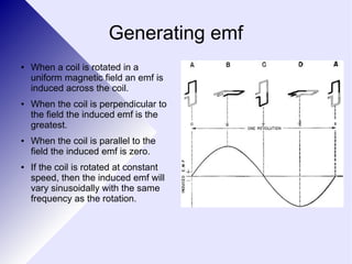
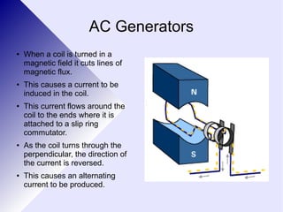
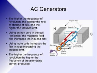
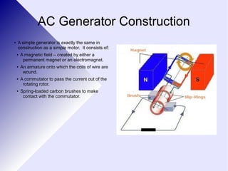
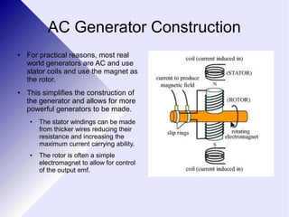
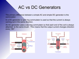
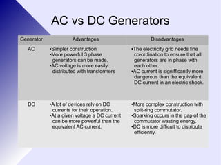
Topic 9.3 
3.3.1 Generators
Generating emf 
● When a coil is rotated in a 
uniform magnetic field an emf is 
induced across the coil. 
● When the coil is perpendicular to 
the field the induced emf is the 
greatest. 
● When the coil is parallel to the 
field the induced emf is zero. 
● If the coil is rotated at constant 
speed, then the induced emf will 
vary sinusoidally with the same 
frequency as the rotation.
AC Generators 
● When a coil is turned in a 
magnetic field it cuts lines of 
magnetic flux. 
● This causes a current to be 
induced in the coil. 
● This current flows around the 
coil to the ends where it is 
attached to a slip ring 
commutator. 
● As the coil turns through the 
perpendicular, the direction of 
the current is reversed. 
● This causes an alternating 
current to be produced.
Induced EMF 
(beyond Syllabus) 
● The flux linkage of a coil of N turns and cross 
sectional area A in a uniform magnetic field B is 
given by: 
Φ=NBA 
● If this coil is rotating then the flux linkage when 
the normal to the plane of the coil makes an 
angle θ to the field becomes: 
Φ=NBA cosθ
Induced EMF 
(beyond Syllabus) 
● The induced emf is therefore given by the rate 
of change of flux linkage: 
Δ t =NBA Δ cosθ 
Δ t 
ε=Δ Φ 
● It can be shown that this is the same as: 
ε=NBAsin θ Δ θ 
● Where is the angular velocity (ω) in rads-1 
Δ θ 
Δ t 
● Therefore: 
Δ t 
ε=NBA(sin ωt)ω
Induced EMF 
(beyond Syllabus) 
● The maximum emf is therefore when sin(ωt) = 
1 
● Therefore 
εmax=ω NBA 
● Note that this implies that if the frequency of 
rotation is doubled then the frequency of the 
emf will double as will the peak emf.
AC Generators 
● The higher the frequency of 
revolution, the greater the rate 
of change of flux, and the 
higher the induced emf. 
● Using an iron core in the coil 
“amplifies” the magnetic field 
and increases the induced emf. 
● Using more coils increases the 
flux linkage increasing the 
induced emf. 
● The higher the frequency of 
revolution the higher the 
frequency of the alternating 
current produced.
AC Generator Construction 
● A simple generator is exactly the same in 
construction as a simple motor. It consists of: 
● A magnetic field – created by either a 
permanent magnet or an electromagnet. 
● An armature onto which the coils of wire are 
wound. 
● A commutator to pass the current out of the 
rotating rotor. 
● Spring-loaded carbon brushes to make 
contact with the commutator.
AC Generator Construction 
● For practical reasons, most real 
world generators are AC and use 
stator coils and use the magnet as 
the rotor. 
● This simplifies the construction of 
the generator and allows for more 
powerful generators to be made. 
● The stator windings can be made 
from thicker wires reducing their 
resistance and increasing the 
maximum current carrying ability. 
● The rotor is often a simple 
electromagnet to allow for control 
of the output emf.
AC vs DC Generators 
The primary difference between a simple AC and simple DC generator is the 
commutator. 
In a DC generator a split ring commutator is used so that the current is always 
coming out in the same direction. 
An AC generator uses a slip ring commutator so that each end of the coil is always 
attached to the same brush. This means that the output current changes direction 
every 180°.
AC vs DC Generators 
Generator Advantages Disadvantages 
AC ●Simpler construction 
●More powerful 3 phase 
generators can be made. 
●AC voltage is more easily 
distributed with transformers 
●The electricity grid needs fine 
co-ordination to ensure that all 
generators are in phase with 
each other. 
●AC current is signifficantly more 
dangerous than the equivalent 
DC current in an electric shock. 
DC ●A lot of devices rely on DC 
currents for their operation. 
●At a given voltage a DC current 
can be more powerful than the 
equivalent AC current. 
●More complex construction with 
split-ring commutator. 
●Sparking occurs in the gap of the 
commutator wasting energy. 
●DC is more difficult to distribute 
efficiently.
Power Losses in Transmission Lines 
● Electricity is generated at around 10000V, 50Hz. 
● If the electricity was transmitted, at this voltage then 
the currents in the transmission wires would be very 
large. 
● This will cause heating effects in the wires due to 
P=I2R. 
● For this reason electricity is stepped up to around 
400kV using a transformer for transmission thereby 
reducing the current and the power losses.
Power Losses 
● As well as the heating effect in the transmission 
wires due to the current and the wires' 
resistance, there are other power losses. 
● Dielectric losses – The insulation material acts as a 
capacitor and causes energy to be lost as heat. 
● Skin effect – the alternating E and B fields in the 
wires causes self-inductance and slows the 
movement of electrons at the outside of the wire. 
This effectively makes the wire thinner. 
● Transformer losses
Power Transmission 
● Electricity is generated in a power station 
at around 10kV by rotating a coil in a 
magnetic field. 
● All generators in all power stations on the 
same grid are synchronised such that they 
all produce electricity that oscillates 
together. 
● Three windings are used on the generator 
to produce 3-phase electricity. This allows 
for more efficient generation 
●
Power Transmission 
● The main substation 
steps up the voltage 
(and the current 
down) to around 
400kV or higher for 
transmission. 
● Each pylon carries 
wires for all three 
phases. 
●
Power Transmission 
● The transmission 
substation reduces 
the voltage to around 
11kV for localised 
transmission. 
● This increases the 
current in the wires 
but reduces the costs 
of power poles and 
increases safety. 
●
Power Transmission 
● A distribution substation steps 
the voltage down to 240V for 
local transmission to houses. 
● Some businesses and houses 
require 2 or three phase 
power whilst others need 
single phase. 
● If power is accessed between 
phases then 415V is available 
for use.
Transmission Lines 
● Power lines are usually carried 
above ground for economic 
reasons and for ease of installation 
and maintenance. 
● However, the power lines, which 
are almost always bare, must be 
insulated from the metal pylons to 
prevent the pylons becoming live or 
the wires short circuiting. 
● The wires are therefore suspended 
from porcelain, glass or ceramic 
discs which are strong and very 
good insulators even under high 
voltages.
Transmission Lines 
● In order to try to prevent 
surges and damage due to 
lightning strikes, the pylons 
usually have another wire at 
their highest point. 
● This wire is connected 
directly to the Earth at 
regular intervals and provides 
a very low resistance path for 
the lightning surge to travel 
down if it is struck, thereby 
saving the transmission lines.
The Battle of the Currents 
● Edison was the first person to set up an electricity company in the 
1880s. 
● He had selected DC for his system and produced light bulbs for homes 
and streets and developed DC motors and appliances. 
● Edison built power stations in the individual suburbs of New York and 
ran cables directly to his customers within a 1 mile (1.6km) radius. 
● Edison's DC system was transmitted at a fixed voltage of 100V as this 
was deemed safe enough for general use and because his Edison 
appliances were designed to run at this voltage. 
● His cables were limited by length as if they were any longer, the 
resistance of the wire itself was enough to reduce the voltage too far 
below 100V to be useful.
The Battle of the Currents 
● Westinghouse bought patents from Nicola Tesla and built AC 
motors and appliances to run on his AC electricity supply. 
● Westinghouse used transformers to increase the voltage up to 
very high levels for transmission over long distances. 
● He was convinced that his system of AC with transformers was 
far more efficient. 
● He was also able to use transformers to increase and decrease 
the voltage at will to supply different appliances. 
● Westinghouse won a competition to build a power station at 
Niagara falls in 1886 and his AC system proved to be so efficient 
that it eventually marked the downfall of mains DC.

3.3.1 generators

  • 1.
    Topic 9.3 3.3.1Generators
  • 2.
    Generating emf ●When a coil is rotated in a uniform magnetic field an emf is induced across the coil. ● When the coil is perpendicular to the field the induced emf is the greatest. ● When the coil is parallel to the field the induced emf is zero. ● If the coil is rotated at constant speed, then the induced emf will vary sinusoidally with the same frequency as the rotation.
  • 3.
    AC Generators ●When a coil is turned in a magnetic field it cuts lines of magnetic flux. ● This causes a current to be induced in the coil. ● This current flows around the coil to the ends where it is attached to a slip ring commutator. ● As the coil turns through the perpendicular, the direction of the current is reversed. ● This causes an alternating current to be produced.
  • 4.
    Induced EMF (beyondSyllabus) ● The flux linkage of a coil of N turns and cross sectional area A in a uniform magnetic field B is given by: Φ=NBA ● If this coil is rotating then the flux linkage when the normal to the plane of the coil makes an angle θ to the field becomes: Φ=NBA cosθ
  • 5.
    Induced EMF (beyondSyllabus) ● The induced emf is therefore given by the rate of change of flux linkage: Δ t =NBA Δ cosθ Δ t ε=Δ Φ ● It can be shown that this is the same as: ε=NBAsin θ Δ θ ● Where is the angular velocity (ω) in rads-1 Δ θ Δ t ● Therefore: Δ t ε=NBA(sin ωt)ω
  • 6.
    Induced EMF (beyondSyllabus) ● The maximum emf is therefore when sin(ωt) = 1 ● Therefore εmax=ω NBA ● Note that this implies that if the frequency of rotation is doubled then the frequency of the emf will double as will the peak emf.
  • 7.
    AC Generators ●The higher the frequency of revolution, the greater the rate of change of flux, and the higher the induced emf. ● Using an iron core in the coil “amplifies” the magnetic field and increases the induced emf. ● Using more coils increases the flux linkage increasing the induced emf. ● The higher the frequency of revolution the higher the frequency of the alternating current produced.
  • 8.
    AC Generator Construction ● A simple generator is exactly the same in construction as a simple motor. It consists of: ● A magnetic field – created by either a permanent magnet or an electromagnet. ● An armature onto which the coils of wire are wound. ● A commutator to pass the current out of the rotating rotor. ● Spring-loaded carbon brushes to make contact with the commutator.
  • 9.
    AC Generator Construction ● For practical reasons, most real world generators are AC and use stator coils and use the magnet as the rotor. ● This simplifies the construction of the generator and allows for more powerful generators to be made. ● The stator windings can be made from thicker wires reducing their resistance and increasing the maximum current carrying ability. ● The rotor is often a simple electromagnet to allow for control of the output emf.
  • 10.
    AC vs DCGenerators The primary difference between a simple AC and simple DC generator is the commutator. In a DC generator a split ring commutator is used so that the current is always coming out in the same direction. An AC generator uses a slip ring commutator so that each end of the coil is always attached to the same brush. This means that the output current changes direction every 180°.
  • 11.
    AC vs DCGenerators Generator Advantages Disadvantages AC ●Simpler construction ●More powerful 3 phase generators can be made. ●AC voltage is more easily distributed with transformers ●The electricity grid needs fine co-ordination to ensure that all generators are in phase with each other. ●AC current is signifficantly more dangerous than the equivalent DC current in an electric shock. DC ●A lot of devices rely on DC currents for their operation. ●At a given voltage a DC current can be more powerful than the equivalent AC current. ●More complex construction with split-ring commutator. ●Sparking occurs in the gap of the commutator wasting energy. ●DC is more difficult to distribute efficiently.
  • 12.
    Power Losses inTransmission Lines ● Electricity is generated at around 10000V, 50Hz. ● If the electricity was transmitted, at this voltage then the currents in the transmission wires would be very large. ● This will cause heating effects in the wires due to P=I2R. ● For this reason electricity is stepped up to around 400kV using a transformer for transmission thereby reducing the current and the power losses.
  • 13.
    Power Losses ●As well as the heating effect in the transmission wires due to the current and the wires' resistance, there are other power losses. ● Dielectric losses – The insulation material acts as a capacitor and causes energy to be lost as heat. ● Skin effect – the alternating E and B fields in the wires causes self-inductance and slows the movement of electrons at the outside of the wire. This effectively makes the wire thinner. ● Transformer losses
  • 14.
    Power Transmission ●Electricity is generated in a power station at around 10kV by rotating a coil in a magnetic field. ● All generators in all power stations on the same grid are synchronised such that they all produce electricity that oscillates together. ● Three windings are used on the generator to produce 3-phase electricity. This allows for more efficient generation ●
  • 15.
    Power Transmission ●The main substation steps up the voltage (and the current down) to around 400kV or higher for transmission. ● Each pylon carries wires for all three phases. ●
  • 16.
    Power Transmission ●The transmission substation reduces the voltage to around 11kV for localised transmission. ● This increases the current in the wires but reduces the costs of power poles and increases safety. ●
  • 17.
    Power Transmission ●A distribution substation steps the voltage down to 240V for local transmission to houses. ● Some businesses and houses require 2 or three phase power whilst others need single phase. ● If power is accessed between phases then 415V is available for use.
  • 18.
    Transmission Lines ●Power lines are usually carried above ground for economic reasons and for ease of installation and maintenance. ● However, the power lines, which are almost always bare, must be insulated from the metal pylons to prevent the pylons becoming live or the wires short circuiting. ● The wires are therefore suspended from porcelain, glass or ceramic discs which are strong and very good insulators even under high voltages.
  • 19.
    Transmission Lines ●In order to try to prevent surges and damage due to lightning strikes, the pylons usually have another wire at their highest point. ● This wire is connected directly to the Earth at regular intervals and provides a very low resistance path for the lightning surge to travel down if it is struck, thereby saving the transmission lines.
  • 20.
    The Battle ofthe Currents ● Edison was the first person to set up an electricity company in the 1880s. ● He had selected DC for his system and produced light bulbs for homes and streets and developed DC motors and appliances. ● Edison built power stations in the individual suburbs of New York and ran cables directly to his customers within a 1 mile (1.6km) radius. ● Edison's DC system was transmitted at a fixed voltage of 100V as this was deemed safe enough for general use and because his Edison appliances were designed to run at this voltage. ● His cables were limited by length as if they were any longer, the resistance of the wire itself was enough to reduce the voltage too far below 100V to be useful.
  • 21.
    The Battle ofthe Currents ● Westinghouse bought patents from Nicola Tesla and built AC motors and appliances to run on his AC electricity supply. ● Westinghouse used transformers to increase the voltage up to very high levels for transmission over long distances. ● He was convinced that his system of AC with transformers was far more efficient. ● He was also able to use transformers to increase and decrease the voltage at will to supply different appliances. ● Westinghouse won a competition to build a power station at Niagara falls in 1886 and his AC system proved to be so efficient that it eventually marked the downfall of mains DC.