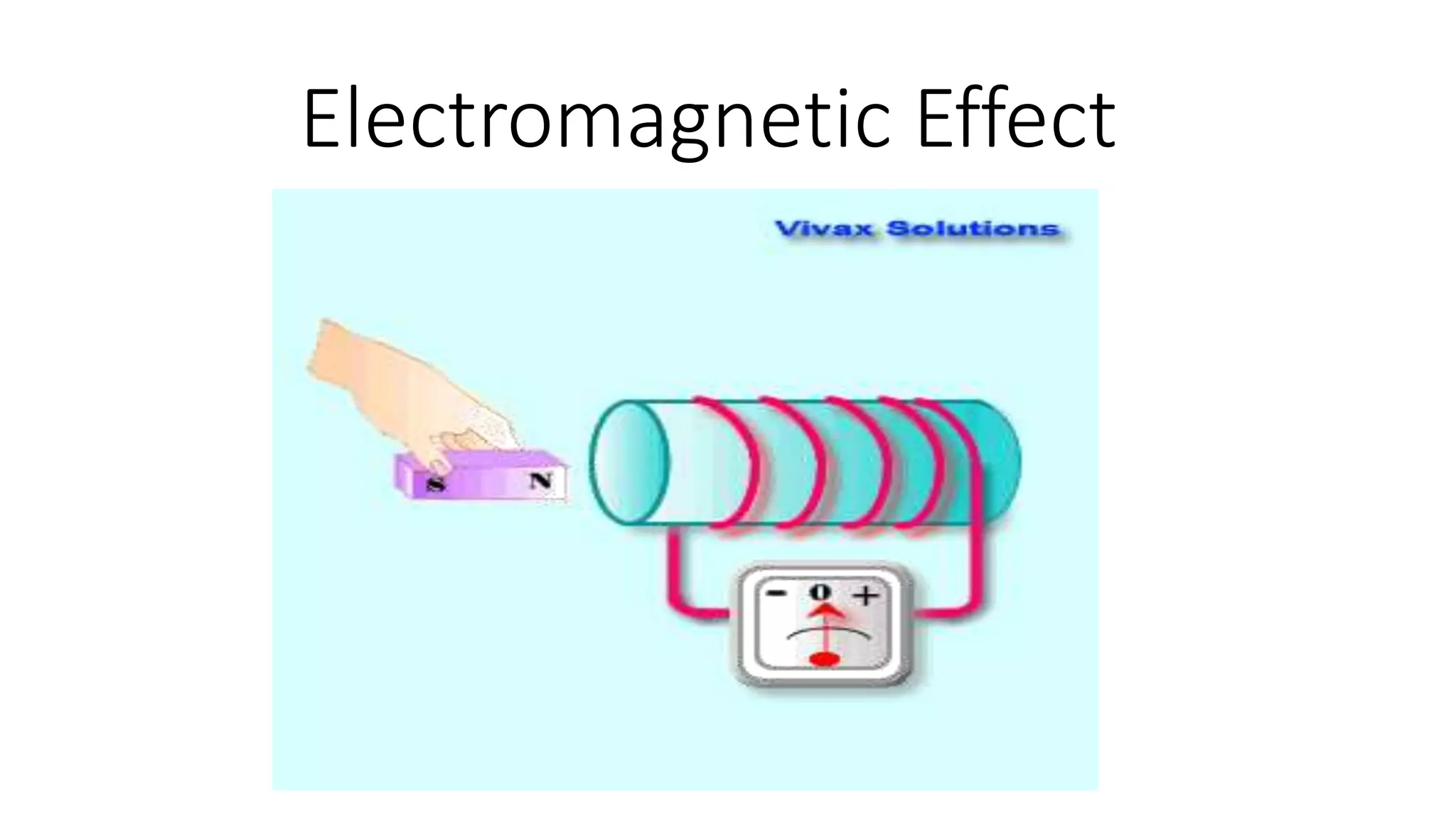
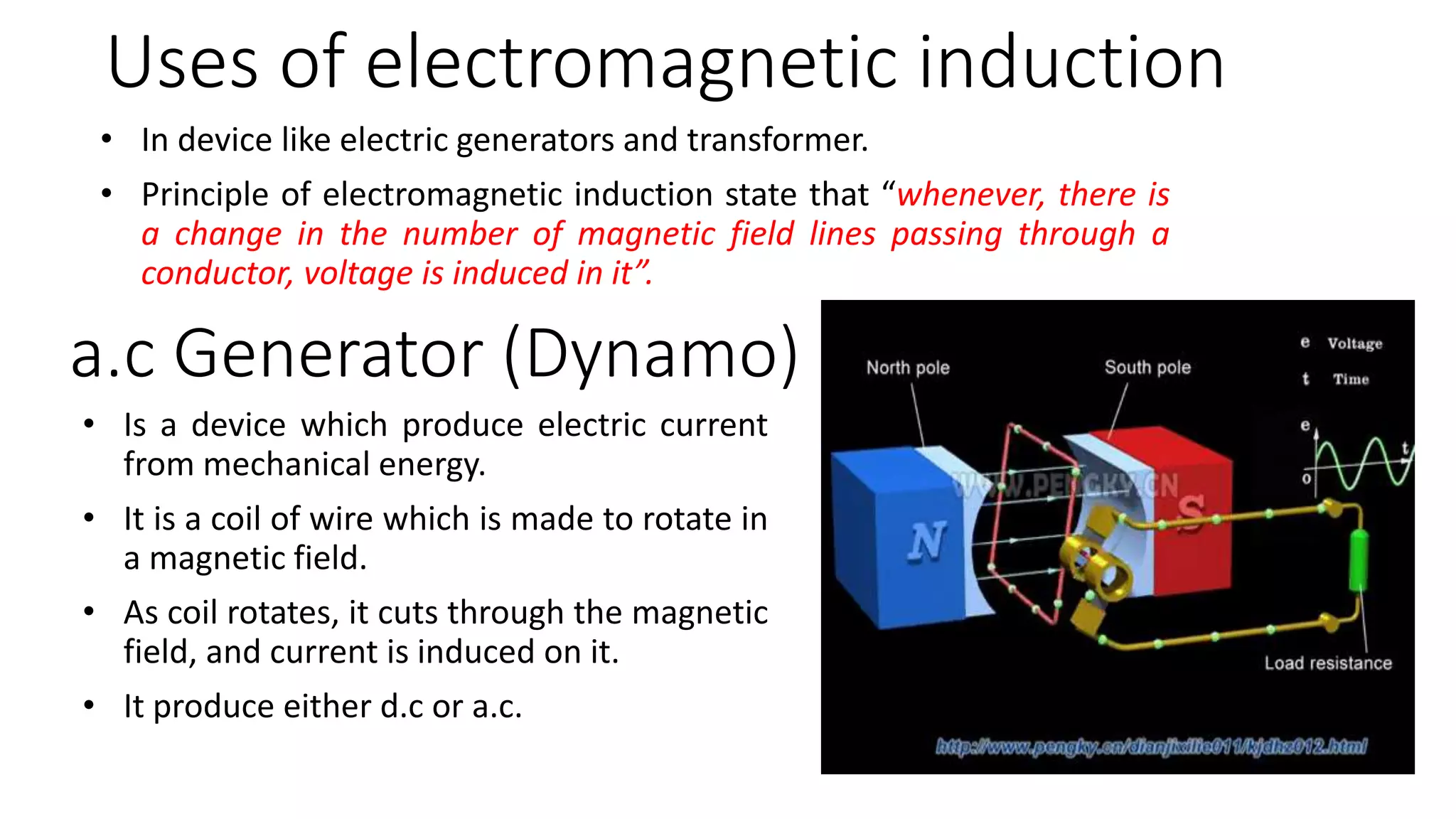
1. Electromagnetic induction occurs when a changing magnetic field induces a current in a conductor. This can be generated by moving a magnet near a coil or changing the current in a neighboring circuit.
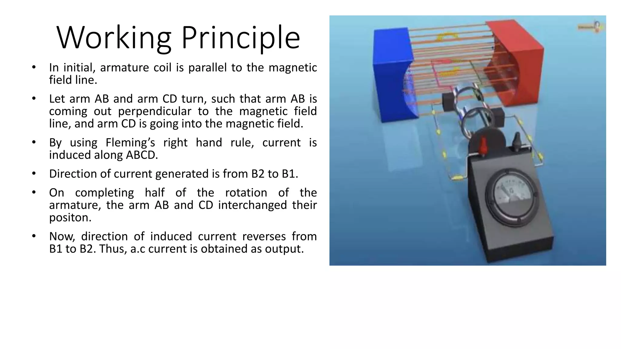
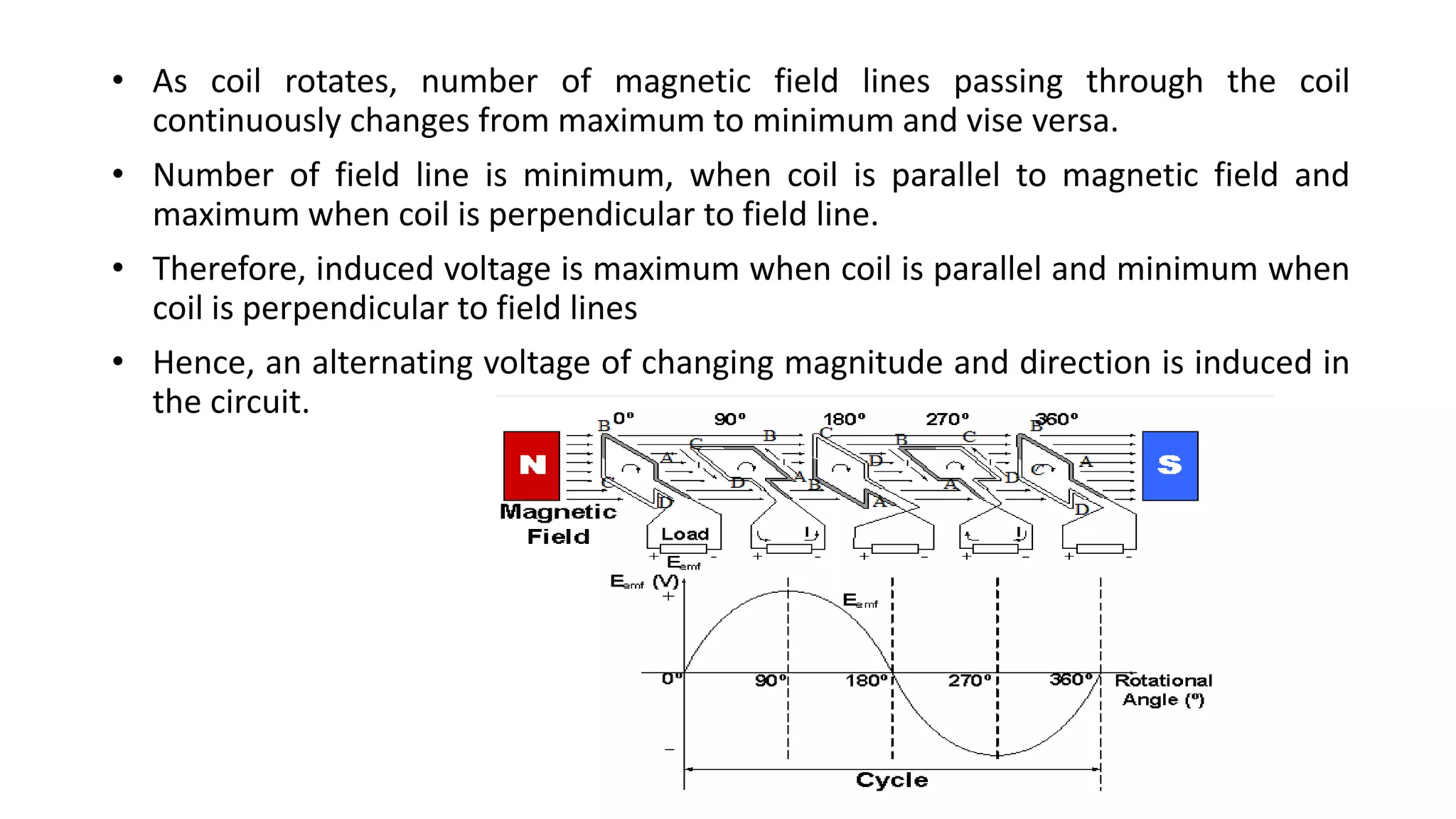
2. Faraday's law states that an electromotive force (EMF) is induced in a conductor whenever the magnetic flux through the conductor changes. The magnitude of the induced EMF is proportional to the rate of change of flux.
3. Transformers use electromagnetic induction to change the voltage of alternating current. A step-up transformer increases voltage by having fewer turns in the primary coil, while a step-down transformer decreases voltage with more turns in the primary coil.