Downloaded 123 times
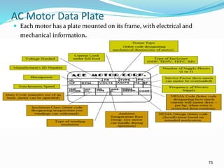
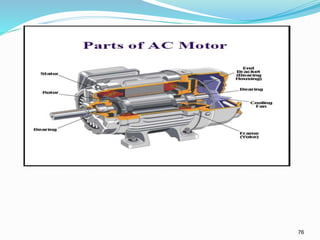
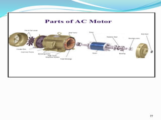
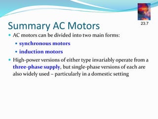
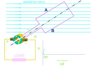
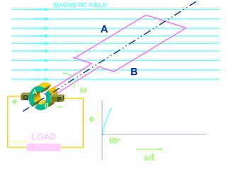
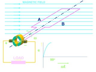
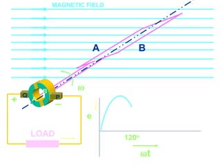
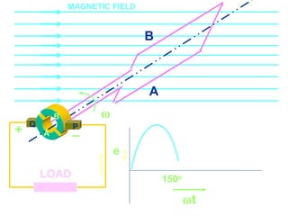
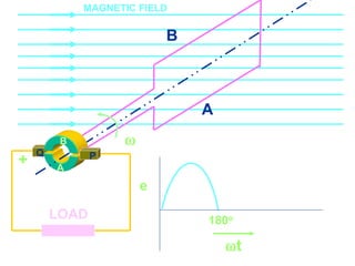
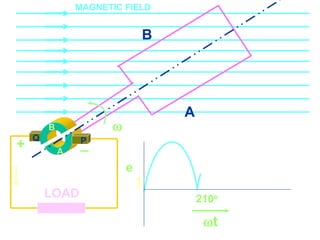
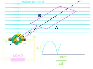
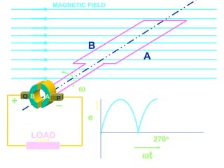
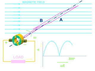
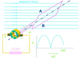
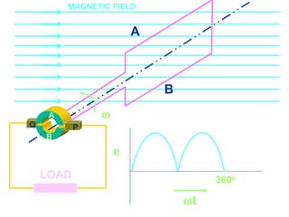


The document details the components and operation of AC generators, including the field, armature, rotor, stator, and slip rings, as well as discussing types, ratings, and efficiency of generators. It covers loss mechanisms such as internal voltage drop, hysteresis, and mechanical losses, and describes the different types of AC generators, including stationary field and rotating armature configurations. Additionally, it explains three-phase generators and AC motors, highlighting their structure, operating principles, and characteristics.