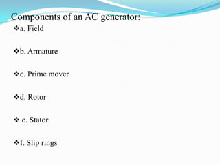
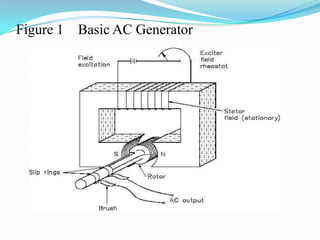
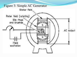
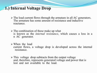
AC Generator
Componentsof an AC generator:a. Field
b. Armature
c. Prime mover
d. Rotor
 e. Stator
f. Slip ringsFieldThe field in an AC generator consists of coils of conductors within the generator that receive a voltage from a source (called excitation) and produce a magnetic flux.  
The magnetic flux in the field cuts the armature to produce a voltage.  This voltage is ultimately the output voltage of the AC generator. ArmatureThe  armature  is  the  part  of  an  AC  generator  in  which  voltage  is  produced.    
This  component consists  of  many  coils  of  wire  that  are  large  enough to  carry  the  full-load  current  of  the generator.Prime MoverThe prime mover is the component that is used to drive the AC generator.  
The prime mover may be any type of rotating machine, such as a diesel engine, a steam turbine, or a motor. RotorThe rotor of an AC generator is the rotating component of the generator, as shown in Figure 1.
The rotor is driven by the generator’s prime mover, which may be a steam turbine, gas turbine, or diesel engine.   
Depending on the type of generator, this component may be the armature or the field.  
 The rotor will be the armature if the voltage output is generated there; the rotor will be the field if the field excitation is applied there.Figure 1    Basic AC Generator
StatorThe  stator  of an AC generator is the part that is stationary (refer to Figure 1).  
 Like the rotor, this component may be the armature or the field, depending on the type of generator.  
The stator will be  the  armature  if the  voltage  output  is generated  there;  the  stator will  be  the  field  if  the field excitation is applied there.Slip RingsSlip rings are electrical connections that are used to transfer power to and from the rotor of an AC generator (refer to Figure 1).   
The slip ring consists of a circular conducting material that is connected to the rotor windings and insulated from the shaft.  
 Brushes ride on the slip ring as the rotor rotates.
 The electrical connection to the rotor is made by connections to the brushes.
Slip rings are used in AC generators because the desired output of the generator is a sine wave. Slip Rings In a DC generator, a commutator was used to provide an output whose current always flowed in  the  positive  direction,  as  shown  in  Figure  2.   
 This  is  not  necessary  for  an  AC  generator.
Therefore, an AC generator may use slip rings, which will allow the output current and voltage to oscillate through positive and negative values.   
This oscillation of voltage and current takes the shape of a sine wave.Figure 2 - Comparison of DC and AC Generator Outputs
Theory of OperationThe strong magnetic  field  is  produced  by  a current flow through the field coil of the rotor.   
The field coil in the rotor  receives  excitation  through the  use  of  slip  rings  and  brushes.
Two   brushes   are   spring-held   in contact   with   the   slip   rings   to provide the continuous connection between   the   field   coil   and   the external excitation circuit.   
The armature is contained within the windings of the stator and is connected to the output.  Theory of OperationEach time the rotor makes one complete revolution, one complete cycle of AC is developed.   
A generator has many turns of wire wound into the slots of the rotor.
The magnitude of AC voltage generated by an AC generator is dependent on the field strength and speed of the rotor.
 Most generators are operated at a constant speed; therefore, the generated voltage depends on field excitation, or strength.A simple AC generator consists of: (a)   a   strong   magnetic   field,   (b) conductors that rotate through that magnetic field, and c) a means by which  a  continuous  connection  is provided to the conductors as they are rotating (Figure 3).  
Figure 3: Simple AC Generator
The frequency of the generated voltage is dependent on the number of field poles and the speed at which the generator is operated,as indicated in Equation . f   = NP/120 	where:		f = frequency (Hz) 		P = total number of poles 		N = rotor speed (rpm) 		120 = conversion from minutes to seconds and from poles to 		pole pairs The 120 in Equation is derived by multiplying the following conversion factors. 60  seconds  x   2  poles			1  minute 	 pole pair In this manner, the units of frequency (hertz or cycles/sec.) are derived.
Losses in an AC Generator
1.) Internal Voltage DropThe load current flows through the armature in all AC generators. The armature has some amount of resistance and inductive reactance.  
The combination of these make up what is  known  as  the  internal  resistance,  which  causes  a  loss  in  an  AC  generator.  
When  the  load current  flows,  a  voltage  drop  is  developed  across  the  internal  resistance.
This  voltage  drop subtracts from the output voltage and, therefore, represents generated voltage and power that is lost  and  not  available  to  the  load.    The  voltage  drop  in  an  AC  generator  can  be  found  using Equation.  Voltage  drop = IaRaIaXLa	where :Ia =     armature current 			Ra =     armature resistance XLa    =     armature inductive reactance
2.) Hysteresis LossesHysteresis  losses  occur  when  iron  cores  in  an  AC  generator  are  subject  to  effects  from  a magnetic  field.    
The  magnetic  domains  of  the  cores  are  held  in  alignment  with  the  field  in varying numbers, dependent upon field strength.   
The magnetic domains rotate, with respect to the  domains  not  held  in  alignment,  one  complete  turn  during  each  rotation  of  the  rotor.
 This rotation  of  magnetic  domains  in  the  iron  causes  friction  and  heat.   2.) Hysteresis LossesThe  heat  produced  by  this friction is called magnetic hysteresis loss.
After the heat-treated silicon steel is formed to the desired shape, the laminations are heated to a dull red and then allowed to cool.   
This process, known as annealing, reduces hysteresis losses to a very low value.

F:\Ac Generator Ppt

  • 1.
  • 3.
    Componentsof an ACgenerator:a. Field
  • 4.
  • 5.
  • 6.
  • 7.
  • 8.
    f. Slip ringsFieldThe field inan AC generator consists of coils of conductors within the generator that receive a voltage from a source (called excitation) and produce a magnetic flux.  
  • 9.
    The magnetic fluxin the field cuts the armature to produce a voltage.  This voltage is ultimately the output voltage of the AC generator. ArmatureThe  armature  is  the  part  of  an  AC  generator  in  which  voltage  is  produced.    
  • 10.
    This  component consists of  many  coils  of  wire  that  are  large  enough to  carry  the  full-load  current  of  the generator.Prime MoverThe prime mover is the component that is used to drive the AC generator.  
  • 11.
    The prime movermay be any type of rotating machine, such as a diesel engine, a steam turbine, or a motor. RotorThe rotor of an AC generator is the rotating component of the generator, as shown in Figure 1.
  • 12.
    The rotor isdriven by the generator’s prime mover, which may be a steam turbine, gas turbine, or diesel engine.   
  • 13.
    Depending on thetype of generator, this component may be the armature or the field.  
  • 14.
     The rotor willbe the armature if the voltage output is generated there; the rotor will be the field if the field excitation is applied there.Figure 1    Basic AC Generator
  • 15.
    StatorThe  stator  of an ACgenerator is the part that is stationary (refer to Figure 1).  
  • 16.
     Like the rotor,this component may be the armature or the field, depending on the type of generator.  
  • 17.
    The stator willbe  the  armature  if the  voltage  output  is generated  there;  the  stator will  be  the  field  if  the field excitation is applied there.Slip RingsSlip rings are electrical connections that are used to transfer power to and from the rotor of an AC generator (refer to Figure 1).   
  • 18.
    The slip ringconsists of a circular conducting material that is connected to the rotor windings and insulated from the shaft.  
  • 19.
     Brushes ride onthe slip ring as the rotor rotates.
  • 20.
     The electrical connectionto the rotor is made by connections to the brushes.
  • 21.
    Slip rings areused in AC generators because the desired output of the generator is a sine wave. Slip Rings In a DC generator, a commutator was used to provide an output whose current always flowed in  the  positive  direction,  as  shown  in  Figure  2.   
  • 22.
     This  is  not necessary  for  an  AC  generator.
  • 23.
    Therefore, an ACgenerator may use slip rings, which will allow the output current and voltage to oscillate through positive and negative values.   
  • 24.
    This oscillation ofvoltage and current takes the shape of a sine wave.Figure 2 - Comparison of DC and AC Generator Outputs
  • 25.
    Theory of OperationThestrong magnetic  field  is  produced  by  a current flow through the field coil of the rotor.   
  • 26.
    The field coilin the rotor  receives  excitation  through the  use  of  slip  rings  and  brushes.
  • 27.
    Two   brushes   are  spring-held   in contact   with   the   slip   rings   to provide the continuous connection between   the   field   coil   and   the external excitation circuit.   
  • 28.
    The armature iscontained within the windings of the stator and is connected to the output.  Theory of OperationEach time the rotor makes one complete revolution, one complete cycle of AC is developed.   
  • 29.
    A generator hasmany turns of wire wound into the slots of the rotor.
  • 30.
    The magnitude ofAC voltage generated by an AC generator is dependent on the field strength and speed of the rotor.
  • 31.
     Most generators areoperated at a constant speed; therefore, the generated voltage depends on field excitation, or strength.A simple AC generator consists of: (a)   a   strong   magnetic   field,   (b) conductors that rotate through that magnetic field, and c) a means by which  a  continuous  connection  is provided to the conductors as they are rotating (Figure 3).  
  • 32.
    Figure 3: SimpleAC Generator
  • 33.
    The frequency ofthe generated voltage is dependent on the number of field poles and the speed at which the generator is operated,as indicated in Equation . f   = NP/120 where: f = frequency (Hz) P = total number of poles N = rotor speed (rpm) 120 = conversion from minutes to seconds and from poles to pole pairs The 120 in Equation is derived by multiplying the following conversion factors. 60  seconds x 2  poles 1  minute pole pair In this manner, the units of frequency (hertz or cycles/sec.) are derived.
  • 34.
    Losses in anAC Generator
  • 35.
    1.) Internal VoltageDropThe load current flows through the armature in all AC generators. The armature has some amount of resistance and inductive reactance.  
  • 36.
    The combination ofthese make up what is  known  as  the  internal  resistance,  which  causes  a  loss  in  an  AC  generator.  
  • 37.
    When  the  loadcurrent  flows,  a  voltage  drop  is  developed  across  the  internal  resistance.
  • 38.
    This  voltage  dropsubtracts from the output voltage and, therefore, represents generated voltage and power that is lost  and  not  available  to  the  load.    The  voltage  drop  in  an  AC  generator  can  be  found  using Equation. Voltage  drop = IaRaIaXLa where :Ia =     armature current Ra =     armature resistance XLa    =     armature inductive reactance
  • 39.
    2.) Hysteresis LossesHysteresis losses  occur  when  iron  cores  in  an  AC  generator  are  subject  to  effects  from  a magnetic  field.    
  • 40.
    The  magnetic  domains of  the  cores  are  held  in  alignment  with  the  field  in varying numbers, dependent upon field strength.   
  • 41.
    The magnetic domainsrotate, with respect to the  domains  not  held  in  alignment,  one  complete  turn  during  each  rotation  of  the  rotor.
  • 42.
     This rotation  of magnetic  domains  in  the  iron  causes  friction  and  heat.   2.) Hysteresis LossesThe  heat  produced  by  this friction is called magnetic hysteresis loss.
  • 43.
    After the heat-treatedsilicon steel is formed to the desired shape, the laminations are heated to a dull red and then allowed to cool.   
  • 44.
    This process, knownas annealing, reduces hysteresis losses to a very low value.