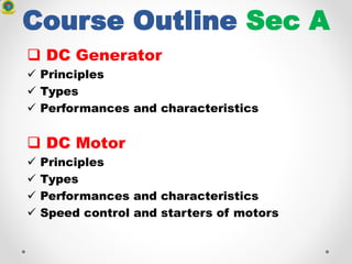
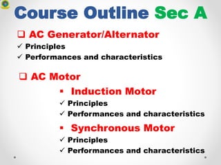
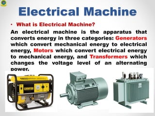
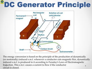
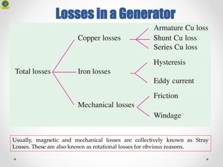
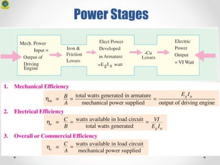
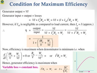
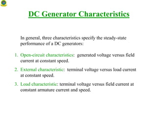
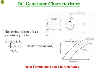
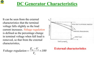
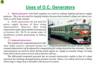
EECE-259
Electrical and
Electronics Technology
Credit 4.00
Contact Hours 4.00
Course Outline Sec A
 DC Generator
 Principles
 Types
 Performances and characteristics
 DC Motor
 Principles
 Types
 Performances and characteristics
 Speed control and starters of motors
Course Outline Sec A
 AC Generator/Alternator
 Principles
 Performances and characteristics
 Induction Motor
 Principles
 Performances and characteristics
 Synchronous Motor
 Principles
 Performances and characteristics
 AC Motor
Course Outline Sec A
 Transformer
 Principles
 Single phase transformer
 Equivalent circuit and laboratory testing
 Losses
 Introduction to three phase transformers
Book References
 A Text Book of Electrical Technology (AC, DC
Machines) – B.L Theraja & A.K. Theraja; S.
Chand & Company Ltd.
 Electrical Machinery Fundamental - Stephan
J. Chapman; McGraw-Hill.
 Direct and Alternating Current Machhinery-
Rosenblatt; Friedman
What is Electricity?
Electricity is energy transported by
the motion of electrons
**We do not make electricity, we
CONVERT other energy sources into
electrical energy**
Energy Conversion Options for Electricity
Non-Thermal Paths
• Source to Electrical
Source Converter
Sun Photovoltaic (photon to electron)
Chemical Fuel Cell
• Source to Potential/Kinetic to Mechanical to Electrical
Source Converter Kinetic to Mechanical Mech to Electrical
Dam Penstocks Turbine (water) Generator
Tides Machine Turbine (air or water) Generator
Wind N/A Turbine (air) Generator
Energy Conversion Options for Electricity
Thermal Paths
• Heat to Mechanical to Electrical
Source Heat to Mechanical Mech to Electrical
Geothermal Turbine (vapor) Generator
OTEC Turbine (vapor) Generator
• Stored Energy to Heat to Mechanical to Electrical
Source Reactor Heat to Mechanical Mech to Electrical
Fuel Combustor Turbine (gas or vapor) Generator
U, Pu Reactor Turbine (gas or vapor) Generator
Sun Collector* Turbine (gas or vapor) Generator
H, H2, H3Reactor Turbine (gas or vapor) Generator
* More a modifier or concentrator than a reactor
Energy Transfer
Chemical
Electrical
Sound
(mechanical)
Light
(Electromagnetic)
Thermal
Mechanical
Where do we get our
Electricity?
• Fossil – Coal, Natural
Gas, Oil – 550 Gigawatts
(GW)
• Nuclear – 200 GW
• Hydro – 75 GW
• Geothermal – 2.3 GW
• Other Renewable –
Wind, Solar, OTEC – 13.6
GW
Electrical Machine
• What is Electrical Machine?
An electrical machine is the apparatus that
converts energy in three categories: Generators
which convert mechanical energy to electrical
energy, Motors which convert electrical energy
to mechanical energy, and Transformers which
changes the voltage level of an alternating
power.
Faraday Effect
• Faraday Effect
• Basic Concepts
• Voltage – V – Potential to Move Charge (volts)
• Current – I – Charge Movement (amperes or amps)
• Resistance – R – V = IxR (R in =ohms)
• Power – P = IxV = I2xR (watts)
Faradays Law
• The EMF generated is proportional to the rate
of change of the magnetic flux.
aabbbbbbbbbbbbbbb
Lenz’s Law
Lenz’s law: If an induced current flows, its direction is
always such that it will oppose the change which
produced it.
Flux decreasing by right move
induces loop flux to the left.
N S
Left motion
I
Induced B
Flux increasing to left induces
loop flux to the right.
N S
Right motionI
Induced B
John Ambrose Fleming Rule
Electric Generator
Electric Motor
Electric Generator
G
Mechanical
Energy
Electrical
Energy
Stationary magnets - rotating magnets - electromagnets
DC Generator Principle
An electrical generator is a machine which converts mechanical energy (or power)
into electrical energy (or power).
DC Generator Principle
The energy conversion is based on the principle of the production of dynamically
(or motionally) induced e.m.f. whenever a conductor cuts magnetic flux, dynamically
induced e.m.f. is produced in it according to Faraday’s Laws of Electromagnetic
Induction. This e.m.f. causes a current to flow if the conductor
circuit is closed.
SINGLE LOOP GENERATOR
Motion is parallel to the flux.
No voltage is induced.
N
S
N
S
Motion is 45° to flux.
Induced voltage is 0.707 of maximum.
SINGLE LOOP GENERATOR
x
N
S
Motion is perpendicular to flux.
Induced voltage is maximum.
SINGLE LOOP GENERATOR
Motion is 45° to flux.
N
S
Induced voltage is 0.707 of maximum.
SINGLE LOOP GENERATOR
N
S
Motion is parallel to flux.
No voltage is induced.
SINGLE LOOP GENERATOR
N
S
Notice current in the
conductor has reversed.
Induced voltage is
0.707 of maximum.
Motion is 45° to flux.
SINGLE LOOP GENERATOR
N
S
Motion is perpendicular to flux.
Induced voltage is maximum.
SINGLE LOOP GENERATOR
N
S
Motion is 45° to flux.
Induced voltage is 0.707 of maximum.
SINGLE LOOP GENERATOR
Motion is parallel to flux.
N
S
No voltage is induced.
Ready to produce another cycle.
SINGLE LOOP GENERATOR
COMMUTATION
For making the flow of current unidirectional in the external circuit, the slip-
rings are replaced by split-rings .The split-rings or commutator are made out of
a conducting cylinder which is cut into two halves or segments insulated from
each other by a thin sheet of mica or some other insulating material. the coil
ends are joined to these segments on which rest the carbon or copper brushes.
COMMUTATION
It is seen (a) that in the first half revolution current flows along (ABMLCD) i.e. the
brush No. 1 in contact with segment ‘a’ acts as the positive end of the supply and ‘b’ as
the negative end. In the next half revolution (b), the direction of the induced current in
the coil has reversed. But at the same time, the positions of segments ‘a’ and ‘b’ have
also reversed with the Fig. result that brush No. 1 comes in touch with the segment
which is positive i.e. segment ‘b’ in this case. Hence, current in the load resistance
again flows from M to L. The waveform of the current through the external circuit is as
shown in Fig. This current is unidirectional but not continuous like pure direct current.
Practical Generator
1. Magnetic Frame or
Yoke
2. Pole-Cores and Pole-
Shoes
3. Pole Coils or Field
Coils
4. Armature Core
5. Armature Windings
or Conductors
6. Commutator
7. Brushes and Bearings
DC Machine Construction
Armature Windings
Lap and Wave Windings
Two types of windings mostly employed for drum-type armatures are known as
Lap Winding and Wave Winding. The difference between the two is merely due to
the different arrangement of the end connections at the front or commutator end of
armature. Each winding can be arranged progressively or retrogressively and
connected in simplex, duplex and triplex.
Armature Windings
Uses of Lap and Wave Windings
The advantage of the wave winding is that, for a given number of poles and
armature conductors, it gives more e.m.f. than the lap winding.
Conversely, for the same e.m.f., lap winding would require large number of
conductors which will result in higher winding cost and less efficient utilization of
space in the armature slots.
Hence, wave winding is suitable for small generators especially those meant for 500-
600 V circuits.
Another advantage is that in wave winding, equalizing connections are not
necessary whereas in a lap winding they definitely are.
However, when large currents are required, it is necessary to use lap winding,
because it gives more parallel paths.
Hence, lap winding is suitable for comparatively low-voltage but high-current
generators whereas wave-winding is used for high-voltage, low-current machines.
Types of Generators
E.M.F. Equation of a Generator
Iron / Core Loss in Armature
(i) Hysteresis Loss (Wh)
If the magnetic field applied to a
magnetic material is increased
and then decreased back to its
original value, the magnetic field
inside the material does not return
to its original value. The internal
field 'lags' behind the external
field. This behaviour results in a
loss of energy, called the
hysteresis loss, when a sample is
repeatedly magnetized and
demagnetized.
Iron / Core Loss in Armature
(ii) Eddy Current Loss (We)
When the armature core rotates, it
also cuts the magnetic flux. Hence,
an e.m.f. is induced in the body of
the core according to the laws of
electromagnetic induction. This
e.m.f. though small, sets up large
current in the body of the core
due to its small resistance. This
current is known as eddy current.
The power loss due to the flow of
this current is known as eddy
current loss. This loss would be
considerable if solid iron core
were used.
Losses in a Generator
Usually, magnetic and mechanical losses are collectively known as Stray
Losses. These are also known as rotational losses for obvious reasons.
Power Stages
Condition for Maximum Efficiency
46
DC Generator Characteristics
In general, three characteristics specify the steady-state
performance of a DC generators:
1. Open-circuit characteristics: generated voltage versus field
current at constant speed.
2. External characteristic: terminal voltage versus load current
at constant speed.
3. Load characteristic: terminal voltage versus field current at
constant armature current and speed.
DC Generator Characteristics
Open-Circuit and Load Characteristics
The terminal voltage of a dc
generator is given by
  
aa
mf
aaat
RI
dropreactionArmatureIf
RIEV



,
DC Generator Characteristics
It can be seen from the external
characteristics that the terminal
voltage falls slightly as the load
current increases. Voltage regulation
is defined as the percentage change
in terminal voltage when full load is
removed, so that from the external
characteristics,
External characteristics
100
V
VE
regulationVoltage
t
ta



Uses of D.C. Generators

Eece 259 dc generator

  • 1.
  • 2.
    Course Outline SecA  DC Generator  Principles  Types  Performances and characteristics  DC Motor  Principles  Types  Performances and characteristics  Speed control and starters of motors
  • 3.
    Course Outline SecA  AC Generator/Alternator  Principles  Performances and characteristics  Induction Motor  Principles  Performances and characteristics  Synchronous Motor  Principles  Performances and characteristics  AC Motor
  • 4.
    Course Outline SecA  Transformer  Principles  Single phase transformer  Equivalent circuit and laboratory testing  Losses  Introduction to three phase transformers
  • 5.
    Book References  AText Book of Electrical Technology (AC, DC Machines) – B.L Theraja & A.K. Theraja; S. Chand & Company Ltd.  Electrical Machinery Fundamental - Stephan J. Chapman; McGraw-Hill.  Direct and Alternating Current Machhinery- Rosenblatt; Friedman
  • 6.
    What is Electricity? Electricityis energy transported by the motion of electrons **We do not make electricity, we CONVERT other energy sources into electrical energy**
  • 7.
    Energy Conversion Optionsfor Electricity Non-Thermal Paths • Source to Electrical Source Converter Sun Photovoltaic (photon to electron) Chemical Fuel Cell • Source to Potential/Kinetic to Mechanical to Electrical Source Converter Kinetic to Mechanical Mech to Electrical Dam Penstocks Turbine (water) Generator Tides Machine Turbine (air or water) Generator Wind N/A Turbine (air) Generator
  • 8.
    Energy Conversion Optionsfor Electricity Thermal Paths • Heat to Mechanical to Electrical Source Heat to Mechanical Mech to Electrical Geothermal Turbine (vapor) Generator OTEC Turbine (vapor) Generator • Stored Energy to Heat to Mechanical to Electrical Source Reactor Heat to Mechanical Mech to Electrical Fuel Combustor Turbine (gas or vapor) Generator U, Pu Reactor Turbine (gas or vapor) Generator Sun Collector* Turbine (gas or vapor) Generator H, H2, H3Reactor Turbine (gas or vapor) Generator * More a modifier or concentrator than a reactor
  • 9.
  • 10.
    Where do weget our Electricity? • Fossil – Coal, Natural Gas, Oil – 550 Gigawatts (GW) • Nuclear – 200 GW • Hydro – 75 GW • Geothermal – 2.3 GW • Other Renewable – Wind, Solar, OTEC – 13.6 GW
  • 11.
    Electrical Machine • Whatis Electrical Machine? An electrical machine is the apparatus that converts energy in three categories: Generators which convert mechanical energy to electrical energy, Motors which convert electrical energy to mechanical energy, and Transformers which changes the voltage level of an alternating power.
  • 12.
    Faraday Effect • FaradayEffect • Basic Concepts • Voltage – V – Potential to Move Charge (volts) • Current – I – Charge Movement (amperes or amps) • Resistance – R – V = IxR (R in =ohms) • Power – P = IxV = I2xR (watts)
  • 14.
    Faradays Law • TheEMF generated is proportional to the rate of change of the magnetic flux. aabbbbbbbbbbbbbbb
  • 15.
    Lenz’s Law Lenz’s law:If an induced current flows, its direction is always such that it will oppose the change which produced it. Flux decreasing by right move induces loop flux to the left. N S Left motion I Induced B Flux increasing to left induces loop flux to the right. N S Right motionI Induced B
  • 16.
    John Ambrose FlemingRule Electric Generator
  • 17.
  • 18.
  • 19.
    DC Generator Principle Anelectrical generator is a machine which converts mechanical energy (or power) into electrical energy (or power).
  • 20.
    DC Generator Principle Theenergy conversion is based on the principle of the production of dynamically (or motionally) induced e.m.f. whenever a conductor cuts magnetic flux, dynamically induced e.m.f. is produced in it according to Faraday’s Laws of Electromagnetic Induction. This e.m.f. causes a current to flow if the conductor circuit is closed.
  • 21.
    SINGLE LOOP GENERATOR Motionis parallel to the flux. No voltage is induced. N S
  • 22.
    N S Motion is 45°to flux. Induced voltage is 0.707 of maximum. SINGLE LOOP GENERATOR
  • 23.
    x N S Motion is perpendicularto flux. Induced voltage is maximum. SINGLE LOOP GENERATOR
  • 24.
    Motion is 45°to flux. N S Induced voltage is 0.707 of maximum. SINGLE LOOP GENERATOR
  • 25.
    N S Motion is parallelto flux. No voltage is induced. SINGLE LOOP GENERATOR
  • 26.
    N S Notice current inthe conductor has reversed. Induced voltage is 0.707 of maximum. Motion is 45° to flux. SINGLE LOOP GENERATOR
  • 27.
    N S Motion is perpendicularto flux. Induced voltage is maximum. SINGLE LOOP GENERATOR
  • 28.
    N S Motion is 45°to flux. Induced voltage is 0.707 of maximum. SINGLE LOOP GENERATOR
  • 29.
    Motion is parallelto flux. N S No voltage is induced. Ready to produce another cycle. SINGLE LOOP GENERATOR
  • 30.
    COMMUTATION For making theflow of current unidirectional in the external circuit, the slip- rings are replaced by split-rings .The split-rings or commutator are made out of a conducting cylinder which is cut into two halves or segments insulated from each other by a thin sheet of mica or some other insulating material. the coil ends are joined to these segments on which rest the carbon or copper brushes.
  • 31.
    COMMUTATION It is seen(a) that in the first half revolution current flows along (ABMLCD) i.e. the brush No. 1 in contact with segment ‘a’ acts as the positive end of the supply and ‘b’ as the negative end. In the next half revolution (b), the direction of the induced current in the coil has reversed. But at the same time, the positions of segments ‘a’ and ‘b’ have also reversed with the Fig. result that brush No. 1 comes in touch with the segment which is positive i.e. segment ‘b’ in this case. Hence, current in the load resistance again flows from M to L. The waveform of the current through the external circuit is as shown in Fig. This current is unidirectional but not continuous like pure direct current.
  • 32.
    Practical Generator 1. MagneticFrame or Yoke 2. Pole-Cores and Pole- Shoes 3. Pole Coils or Field Coils 4. Armature Core 5. Armature Windings or Conductors 6. Commutator 7. Brushes and Bearings
  • 33.
  • 34.
  • 35.
  • 36.
  • 37.
    Armature Windings Lap andWave Windings Two types of windings mostly employed for drum-type armatures are known as Lap Winding and Wave Winding. The difference between the two is merely due to the different arrangement of the end connections at the front or commutator end of armature. Each winding can be arranged progressively or retrogressively and connected in simplex, duplex and triplex.
  • 38.
    Armature Windings Uses ofLap and Wave Windings The advantage of the wave winding is that, for a given number of poles and armature conductors, it gives more e.m.f. than the lap winding. Conversely, for the same e.m.f., lap winding would require large number of conductors which will result in higher winding cost and less efficient utilization of space in the armature slots. Hence, wave winding is suitable for small generators especially those meant for 500- 600 V circuits. Another advantage is that in wave winding, equalizing connections are not necessary whereas in a lap winding they definitely are. However, when large currents are required, it is necessary to use lap winding, because it gives more parallel paths. Hence, lap winding is suitable for comparatively low-voltage but high-current generators whereas wave-winding is used for high-voltage, low-current machines.
  • 39.
  • 40.
    E.M.F. Equation ofa Generator
  • 41.
    E.M.F. Equation ofa Generator
  • 42.
    Iron / CoreLoss in Armature (i) Hysteresis Loss (Wh) If the magnetic field applied to a magnetic material is increased and then decreased back to its original value, the magnetic field inside the material does not return to its original value. The internal field 'lags' behind the external field. This behaviour results in a loss of energy, called the hysteresis loss, when a sample is repeatedly magnetized and demagnetized.
  • 43.
    Iron / CoreLoss in Armature (ii) Eddy Current Loss (We) When the armature core rotates, it also cuts the magnetic flux. Hence, an e.m.f. is induced in the body of the core according to the laws of electromagnetic induction. This e.m.f. though small, sets up large current in the body of the core due to its small resistance. This current is known as eddy current. The power loss due to the flow of this current is known as eddy current loss. This loss would be considerable if solid iron core were used.
  • 44.
    Losses in aGenerator Usually, magnetic and mechanical losses are collectively known as Stray Losses. These are also known as rotational losses for obvious reasons.
  • 45.
  • 46.
    Condition for MaximumEfficiency 46
  • 47.
    DC Generator Characteristics Ingeneral, three characteristics specify the steady-state performance of a DC generators: 1. Open-circuit characteristics: generated voltage versus field current at constant speed. 2. External characteristic: terminal voltage versus load current at constant speed. 3. Load characteristic: terminal voltage versus field current at constant armature current and speed.
  • 48.
    DC Generator Characteristics Open-Circuitand Load Characteristics The terminal voltage of a dc generator is given by    aa mf aaat RI dropreactionArmatureIf RIEV    ,
  • 49.
    DC Generator Characteristics Itcan be seen from the external characteristics that the terminal voltage falls slightly as the load current increases. Voltage regulation is defined as the percentage change in terminal voltage when full load is removed, so that from the external characteristics, External characteristics 100 V VE regulationVoltage t ta   
  • 50.
    Uses of D.C.Generators