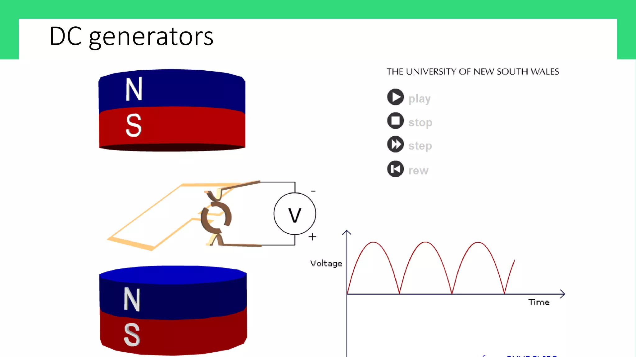
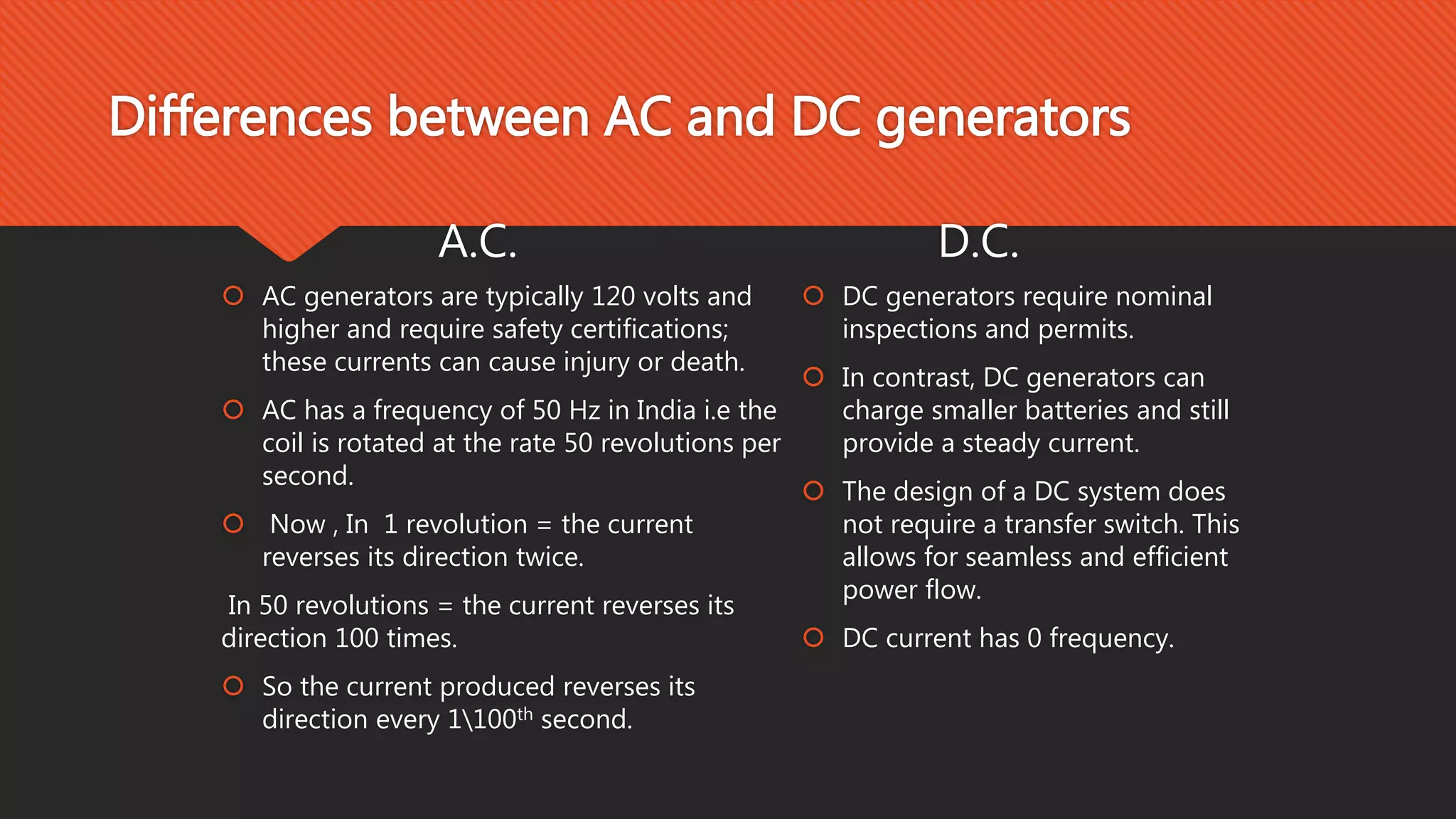
INTRODUCTION
There are two types of generators, one is ac generator and other is dc generator. Whatever
may be the types of generators, it always converts mechanical power to electrical power. An
ac generator produces alternating power. A dc generator produces direct power. Both of
these generators produce electrical power, based on same fundamental principle of
electromagnetic induction.
According to this law, when an conductor moves in a magnetic field it cuts magnetic lines
force, due to which an EMF is induced in the conductor. The magnitude of this induced EMF
depends upon the rate of change of flux (magnetic line force) linkage with the conductor.
This EMF will cause an electric current to flow if the conductor circuit is closed.
Hence the most basic two essential parts of a generator are:
a) a magnetic field and
b) conductors which move inside that magnetic field.
ELECTROMAGNETIC INDUCTION
Electromagnetic induction is the production of an electromotive
force EMF across a conductor when it is exposed to a varying
magnetic field.
EMF- ELECTROMOTIVE FORCE
Electromotive force, also called EMF denoted by Ɛ and
measured in volts. It is the voltage developed by any source
of electrical energy. Basic to the understanding of simple
motors and generators there lies a simple generation of an
electromotive force, an EMF.
The magnetic field is composed of several magnetic field
lines, which carry a force. As the conductor cuts these lines,
an electromotive force or an EMF is generated in the
conductor. Moving the conductor down through the field, will
result deflection of the voltmeter one way, which means the
EMF has one direction. moving the conductor up through the
field, will result in opposite deflection of the needle of the
voltmeter. Moving the conductor back and forth through the
field lines will produce no deflection. there is no EMF because
the conductor is not cutting the field.
EMF of opposite polarities is generated inside an AC
Motion
NS
FLEMING’S RIGHT HAND RULE
Fleming's right hand rule (for generators) shows the direction of
induced current when a conductor moves in a magnetic field.
Motion
Current
NS
COMPONENTS OF A GENERATOR
Rotor Armature Coil
Stator
Field
electromagnets
Brushes
ROTOR
In its simplest form, the rotor
consists of a single loop of wire
made to rotate within a magnetic
field. In practice, the rotor usually
consists of several coils of wire
wound on an armature.
D
A
B
C
ARMATURE
The armature is a cylinder of
laminated iron mounted on an axle.
The axle is carried in bearings
mounted in the external structure
of the generator. Torque is applied
to the axle to make the rotor spin.
FIELD ELECTROMAGNETS
Each electromagnet consists of a coil
of many turns of copper wire wound
on a soft iron core. The
electromagnets are wound, mounted
and shaped in such a way that
opposite poles face each other and
wrap around the rotor.
COIL
Each coil usually consists of many
turns of copper wire wound on the
armature. The two ends of each coil
are connected either to two slip
rings (AC) or two opposite bars of a
split-ring commutator (DC).
BRUSHES
The brushes are carbon blocks that
maintain contact with the ends of the
coils via the slip rings (AC) or the
split-ring commutator (DC), and
conduct electric current from the
coils to the external circuit
STATOR
The stator is the fixed part of the
generator that supplies the magnetic
field in which the coils rotate. It may
consist of two permanent magnets
with opposite poles facing and
shaped to fit around the rotor.
Alternatively, the magnetic field may
be provided by two electromagnets.
A.C. GENERATORS
A.C. GENERATOR
Principal: The A.C generator works on the principal of
electromagnetic induction.
It converts mechanical energy into electrical energy.
Construction: A simple A.C generator consists of a rectangular
coil ABCD, two magnets, slip rings(R1 and R2), brushes(B1 and
B2) and a galvanometer.
G
S N
A
B C
D
SLIP RINGS
R1
R2 B1
B2
GALVANOMETER
CARBON
BRUSHES
G
S N
D
C B
A
SLIP RINGS
R2
R1 B2
B1
GALVANOMETER
CARBON
BRUSHES
COMMERCIAL A.C GENERATORS
In practical generators, to increase the
voltage and the current we :
 Use a powerful electromagnet in place of
a permanent magnet to make magnetic
field stronger.
 Wind the coil around the soft iron to
increase the strength of magnetic field.
 Use a coil with many turns on it so as to
increase the current.
 Rotate the coil faster.
 We use a coil with a larger cross sectional
area.
AC generators
DC GENERATORS
PRINCIPLE
The generator is an application of electromagnetic induction. It works on the
principle that when a wire is moved in a magnetic field, then the current is induced
in the coil. A rectangular coil is made to rotate rapidly in the magnetic field between
the poles of a magnet. When the coil rotates, it cuts the lines of magnetic force, due
to which a current is produced in the generator coil. This current can be used to run
the various electrical appliances.
CONSTRUCTION
Simple loop generator is having a single-turn rectangular copper coil rotating about
its own axis in a magnetic field provided by either permanent magnet or electro
magnets. In case of without commutator the two ends of the coil are joined to slip
rings which are insulated from each other and from the central shaft. Two collecting
brushes (of carbon or copper) press against the slip rings. Their function is to collect
the current induced in the coil. In this case the current waveform we obtain is
alternating current. In case of with commutator the slip rings are replaced by split
rings. In this case the current is unidirectional.
GALVANOMETER
G
N S
A
B C
D
SPLIT
RINGS
R1R2
B1B2
CARBON
BRUSHES
Working
Let us suppose that the generator
coil ABCD is initially in the horizontal
position. As the coil rotates in the
anticlockwise direction between the
pole N and S of the magnet the side
AB of the coil moves down cutting
the magnetic lines of force near the
N-pole of the magnet and side DC
moves up, cutting the lines of force
near the S-pole of the magnet. Due
to this, induced current is produced
in the sides AB and DC of the coil.
GALVANOMETER
G
N S
A
B C
D
SPLIT
RINGS
R1R2
B1B2
CARBON
BRUSHES
Working
On applying Fleming's right hand rule
to the sides AB and DC of the coil we
find that the currents in them are in
the directions B to A and D to C
respectively. Thus the induced
currents in the two sides of the coil
are in the same direction and we get
an effective induced current in the
direction BADC. Due to this the brush
B1 becomes the positive pole and
brush B2 becomes the negative pole
of the generator.
GALVANOMETER
G
N S
D
C B
A
SPLIT
RINGS
R2R1
B1B2
CARBON
BRUSHES
Working
After half revolution, the sides AB and
DC of the coil will interchange their
positions. The side AB will come on the
right hand side and starts moving up
whereas side DC will come on the left
hand side and start moving down. But
when sides of the coil interchange their
positions, then the two commutator
half rings R1 and R2 automatically
change their contacts from one carbon
brush to the other. Due to this change,
the current keeps flowing in the same
direction. Thus a DC generator supplies
a current only in one direction.
DC generators
Differences between AC and DC
Differences between AC and DC generators
A.C
 A.C current is the current that changes
direction after equal intervals of time or
the current that reverses its direction
periodically.
D.C
 D.C current is the current that flows
consistently in one direction.
D.C.
A.C.
Voltage(V)
Time (ms)
Differences between AC and DC generators
A.C.
 In our homes we use A.C current
to provide power to all the
appliances such TV, fridge, etc.
D.C.
 D.C current is often used in
charging the batteries and in all
electronic systems as the source of
power supply.
Differences between AC and DC generators
A.C.
 A.C generators have slip rings
which play a main role in reversing
the direction of the current.
D.C.
 D.C generators have split rings
which play a main role in the
unidirectional flow of current.
Differences between AC and DC generators
A.C.
 AC generators are typically 120 volts and
higher and require safety certifications;
these currents can cause injury or death.
 AC has a frequency of 50 Hz in India i.e the
coil is rotated at the rate 50 revolutions per
second.
 Now , In 1 revolution = the current
reverses its direction twice.
In 50 revolutions = the current reverses its
direction 100 times.
 So the current produced reverses its
direction every 1100th second.
D.C.
 DC generators require nominal
inspections and permits.
 In contrast, DC generators can
charge smaller batteries and still
provide a steady current.
 The design of a DC system does
not require a transfer switch. This
allows for seamless and efficient
power flow.
 DC current has 0 frequency.
Q&A
?
!? !
?!?
?
?
?
?
?
?
?
!
! ???
!
?
!
?
?
!
!
! ?
!
?

AC & DC Generators

  • 3.
    INTRODUCTION There are twotypes of generators, one is ac generator and other is dc generator. Whatever may be the types of generators, it always converts mechanical power to electrical power. An ac generator produces alternating power. A dc generator produces direct power. Both of these generators produce electrical power, based on same fundamental principle of electromagnetic induction. According to this law, when an conductor moves in a magnetic field it cuts magnetic lines force, due to which an EMF is induced in the conductor. The magnitude of this induced EMF depends upon the rate of change of flux (magnetic line force) linkage with the conductor. This EMF will cause an electric current to flow if the conductor circuit is closed. Hence the most basic two essential parts of a generator are: a) a magnetic field and b) conductors which move inside that magnetic field.
  • 4.
    ELECTROMAGNETIC INDUCTION Electromagnetic inductionis the production of an electromotive force EMF across a conductor when it is exposed to a varying magnetic field.
  • 5.
    EMF- ELECTROMOTIVE FORCE Electromotiveforce, also called EMF denoted by Ɛ and measured in volts. It is the voltage developed by any source of electrical energy. Basic to the understanding of simple motors and generators there lies a simple generation of an electromotive force, an EMF. The magnetic field is composed of several magnetic field lines, which carry a force. As the conductor cuts these lines, an electromotive force or an EMF is generated in the conductor. Moving the conductor down through the field, will result deflection of the voltmeter one way, which means the EMF has one direction. moving the conductor up through the field, will result in opposite deflection of the needle of the voltmeter. Moving the conductor back and forth through the field lines will produce no deflection. there is no EMF because the conductor is not cutting the field. EMF of opposite polarities is generated inside an AC Motion NS
  • 6.
    FLEMING’S RIGHT HANDRULE Fleming's right hand rule (for generators) shows the direction of induced current when a conductor moves in a magnetic field. Motion Current NS
  • 7.
    COMPONENTS OF AGENERATOR Rotor Armature Coil Stator Field electromagnets Brushes
  • 8.
    ROTOR In its simplestform, the rotor consists of a single loop of wire made to rotate within a magnetic field. In practice, the rotor usually consists of several coils of wire wound on an armature. D A B C
  • 9.
    ARMATURE The armature isa cylinder of laminated iron mounted on an axle. The axle is carried in bearings mounted in the external structure of the generator. Torque is applied to the axle to make the rotor spin.
  • 10.
    FIELD ELECTROMAGNETS Each electromagnetconsists of a coil of many turns of copper wire wound on a soft iron core. The electromagnets are wound, mounted and shaped in such a way that opposite poles face each other and wrap around the rotor.
  • 11.
    COIL Each coil usuallyconsists of many turns of copper wire wound on the armature. The two ends of each coil are connected either to two slip rings (AC) or two opposite bars of a split-ring commutator (DC).
  • 12.
    BRUSHES The brushes arecarbon blocks that maintain contact with the ends of the coils via the slip rings (AC) or the split-ring commutator (DC), and conduct electric current from the coils to the external circuit
  • 13.
    STATOR The stator isthe fixed part of the generator that supplies the magnetic field in which the coils rotate. It may consist of two permanent magnets with opposite poles facing and shaped to fit around the rotor. Alternatively, the magnetic field may be provided by two electromagnets.
  • 14.
  • 15.
    A.C. GENERATOR Principal: TheA.C generator works on the principal of electromagnetic induction. It converts mechanical energy into electrical energy. Construction: A simple A.C generator consists of a rectangular coil ABCD, two magnets, slip rings(R1 and R2), brushes(B1 and B2) and a galvanometer.
  • 16.
    G S N A B C D SLIPRINGS R1 R2 B1 B2 GALVANOMETER CARBON BRUSHES
  • 17.
    G S N D C B A SLIPRINGS R2 R1 B2 B1 GALVANOMETER CARBON BRUSHES
  • 18.
    COMMERCIAL A.C GENERATORS Inpractical generators, to increase the voltage and the current we :  Use a powerful electromagnet in place of a permanent magnet to make magnetic field stronger.  Wind the coil around the soft iron to increase the strength of magnetic field.  Use a coil with many turns on it so as to increase the current.  Rotate the coil faster.  We use a coil with a larger cross sectional area.
  • 19.
  • 20.
  • 21.
    PRINCIPLE The generator isan application of electromagnetic induction. It works on the principle that when a wire is moved in a magnetic field, then the current is induced in the coil. A rectangular coil is made to rotate rapidly in the magnetic field between the poles of a magnet. When the coil rotates, it cuts the lines of magnetic force, due to which a current is produced in the generator coil. This current can be used to run the various electrical appliances.
  • 22.
    CONSTRUCTION Simple loop generatoris having a single-turn rectangular copper coil rotating about its own axis in a magnetic field provided by either permanent magnet or electro magnets. In case of without commutator the two ends of the coil are joined to slip rings which are insulated from each other and from the central shaft. Two collecting brushes (of carbon or copper) press against the slip rings. Their function is to collect the current induced in the coil. In this case the current waveform we obtain is alternating current. In case of with commutator the slip rings are replaced by split rings. In this case the current is unidirectional.
  • 23.
    GALVANOMETER G N S A B C D SPLIT RINGS R1R2 B1B2 CARBON BRUSHES Working Letus suppose that the generator coil ABCD is initially in the horizontal position. As the coil rotates in the anticlockwise direction between the pole N and S of the magnet the side AB of the coil moves down cutting the magnetic lines of force near the N-pole of the magnet and side DC moves up, cutting the lines of force near the S-pole of the magnet. Due to this, induced current is produced in the sides AB and DC of the coil.
  • 24.
    GALVANOMETER G N S A B C D SPLIT RINGS R1R2 B1B2 CARBON BRUSHES Working Onapplying Fleming's right hand rule to the sides AB and DC of the coil we find that the currents in them are in the directions B to A and D to C respectively. Thus the induced currents in the two sides of the coil are in the same direction and we get an effective induced current in the direction BADC. Due to this the brush B1 becomes the positive pole and brush B2 becomes the negative pole of the generator.
  • 25.
    GALVANOMETER G N S D C B A SPLIT RINGS R2R1 B1B2 CARBON BRUSHES Working Afterhalf revolution, the sides AB and DC of the coil will interchange their positions. The side AB will come on the right hand side and starts moving up whereas side DC will come on the left hand side and start moving down. But when sides of the coil interchange their positions, then the two commutator half rings R1 and R2 automatically change their contacts from one carbon brush to the other. Due to this change, the current keeps flowing in the same direction. Thus a DC generator supplies a current only in one direction.
  • 26.
  • 27.
  • 28.
    Differences between ACand DC generators A.C  A.C current is the current that changes direction after equal intervals of time or the current that reverses its direction periodically. D.C  D.C current is the current that flows consistently in one direction. D.C. A.C. Voltage(V) Time (ms)
  • 29.
    Differences between ACand DC generators A.C.  In our homes we use A.C current to provide power to all the appliances such TV, fridge, etc. D.C.  D.C current is often used in charging the batteries and in all electronic systems as the source of power supply.
  • 30.
    Differences between ACand DC generators A.C.  A.C generators have slip rings which play a main role in reversing the direction of the current. D.C.  D.C generators have split rings which play a main role in the unidirectional flow of current.
  • 31.
    Differences between ACand DC generators A.C.  AC generators are typically 120 volts and higher and require safety certifications; these currents can cause injury or death.  AC has a frequency of 50 Hz in India i.e the coil is rotated at the rate 50 revolutions per second.  Now , In 1 revolution = the current reverses its direction twice. In 50 revolutions = the current reverses its direction 100 times.  So the current produced reverses its direction every 1100th second. D.C.  DC generators require nominal inspections and permits.  In contrast, DC generators can charge smaller batteries and still provide a steady current.  The design of a DC system does not require a transfer switch. This allows for seamless and efficient power flow.  DC current has 0 frequency.
  • 32.