
Recommended
More Related Content
Similar to INFORMATION ABOUT DC MACHINES AND TRANSFORMERES
Similar to INFORMATION ABOUT DC MACHINES AND TRANSFORMERES (20)
Recently uploaded
Recently uploaded (20)
INFORMATION ABOUT DC MACHINES AND TRANSFORMERES
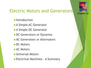
- 1. Electric Motors and Generators Introduction A Simple AC Generator A Simple DC Generator DC Generators or Dynamos AC Generators or Alternators DC Motors AC Motors Universal Motors Electrical Machines – A Summary Chapter 23
- 2. Introduction In this lecture we consider various forms of rotating electrical machines These can be divided into: generators – which convert mechanical energy into electrical energy motors – which convert electrical energy into mechanical energy Both types operate through the interaction between a magnetic field and a set of windings 23.1
- 3. A Simple AC Generator We noted earlier that Faraday’s law dictates that if a coil of N turns experiences a change in magnetic flux, then the induced voltage V is given by If a coil of area A rotates with respect to a field B, and if at a particular time it is at an angle to the field, then the flux linking the coil is BAcos, and the rate of change of flux is given by 23.2 t Φ N V d d cos cos d d d sin d t t BA dt dΦ
- 4. Thus for the arrangement shown below t Φ N V d d cos d sin d d d NBA t NBA t Φ N V
- 5. Therefore this arrangement produces a sinusoidal output as shown below
- 6. Wires connected to the rotating coil would get twisted Therefore we use circular slip rings with sliding contacts called brushes
- 7. A Simple DC Generator The alternating signal from the earlier AC generator could be converted to DC using a rectifier A more efficient approach is to replace the two slip rings with a single split slip ring called a commutator this is arranged so that connections to the coil are reversed as the voltage from the coil changes polarity hence the voltage across the brushes is of a single polarity adding additional coils produces a more constant output 23.3
- 8. Use of a commutator
- 9. A simple generator with two coils
- 10. The ripple can be further reduced by the use of a cylindrical iron core and by shaping the pole pieces this produces an approximately uniform field in the narrow air gap the arrangement of coils and core is known as the armature
- 11. DC Generators or Dynamos Practical DC generators or dynamos can take a number of forms depending on how the magnetic field is produced can use a permanent magnet more often it is generated electrically using field coils current in the field coils can come from an external supply this is known as a separately excited generator but usually the field coils are driven from the generator output this is called a self-excited generator often use multiple poles held in place by a steel tube called the stator 23.4
- 12. A four-pole DC generator
- 13. Field coil excitation sometimes the field coils are connected in series with the armature, sometimes in parallel (shunt) and sometimes a combination of the two (compound) these different forms produce slightly different characteristics diagram here shows a shunt-wound generator
- 14. DC generator characteristics vary slightly between forms examples shown here are for a shunt-wound generator
- 15. AC Generators or Alternators Alternators do not require commutation this allows a simpler construction the field coils are made to rotate while the armature windings are stationary Note: the armature windings are those that produce the output thus the large heavy armature windings are in the stator the lighter field coils are mounted on the rotor and direct current is fed to these by a set of slip rings 23.5
- 16. A four-pole alternator
- 17. As with DC generators multiple poles and sets of windings are used to improve efficiency sometimes three sets of armature windings are spaced 120 apart around the stator to form a three-phase generator The e.m.f. produced is in sync with rotation of the rotor so this is a synchronous generator if the generator has a single set of poles the output frequency is equal to the rotation frequency if additional pole-pairs are used the frequency is increased accordingly
- 18. Example – see Example 23.2 from course text A four-pole alternator is required to operate at 60 Hz. What is the required rotation speed? A four-pole alternator has two pole pairs. Therefore the output frequency is twice the rotation speed. Therefore to operate at 60Hz, the required speed must be 60/2 = 30Hz. This is equivalent to 30 60 = 1800 rpm.
- 19. DC Motors When current flows in a conductor it produces a magnetic field about it - as shown in (a) below when the current-carrying conductor is within an externally generated magnetic field, the fields interact and a force is exerted on the conductor - as in (b) 23.6
- 20. Therefore if a conductor lies within a magnetic field: motion of the conductor produces an electric current an electric current in the conductor will generate motion The reciprocal nature of this relationship means that, for example, the DC generator above will function as a DC motor although machines designed as motors are more efficient in this role Thus the four-pole DC generator shown earlier could equally well be a four- pole DC motor
- 21. DC motor characteristics many forms – each with slightly different characteristics again can be permanent magnet, or series-wound, shunt-wound or compound wound figure below shows a shunt-wound DC motor
- 22. AC Motors AC motors can be divided into two main forms: synchronous motors induction motors High-power versions of either type invariably operate from a three-phase supply, but single-phase versions of each are also widely used – particularly in a domestic setting 23.7
- 23. Synchronous motors just as a DC generator can be used as a DC motor, so AC generators (or alternators) can be used as synchronous AC motors three phase motors use three sets of stator coils the rotating magnetic field drags the rotor around with it single phase motors require some starting mechanism torque is only produced when the rotor is in sync with the rotating magnetic field not self-starting – may be configured as an induction motor until its gets up to speed, then becomes a synchronous motor
- 24. Induction motors these are perhaps the most important form of AC motor rather than use slip rings to pass current to the field coils in the rotor, current is induced in the rotor by transformer action the stator is similar to that in a synchronous motor the rotor is simply a set of parallel conductors shorted together at either end by two conducting rings
- 25. A squirrel-cage induction motor
- 26. In a three-phase induction motor the three phases produce a rotating magnetic field (as in a three-phase synchronous motor) a stationary conductor will see a varying magnetic field and this will induce a current current is induced in the field coils in the same way that current is induced in the secondary of a transformer this current turns the rotor into an electromagnet which is dragged around by the rotating magnetic field the rotor always goes slightly slower than the magnetic field – this is the slip of the motor
- 27. In single-phase induction motors other techniques must be used to produce the rotating magnetic field various techniques are used leading to various forms of motor such as capacitor motors shaded-pole motors such motors are inexpensive and are widely used in domestic applications
- 28. Universal Motors While most motors operate from either AC or DC, some can operate from either These are universal motors and resemble series-wound DC motors, but are designed for both AC and DC operation typically operate at high speed (usually > 10,000 rpm) offer high power-to-weight ratio ideal for portable equipment such as hand drills and vacuum cleaners 23.8
- 29. Electrical Machines – A Summary Power generation is dominated by AC machines range from automotive alternators to the synchronous generators used in power stations efficiency increases with size (up to 98%) Both DC and AC motors are used high-power motors are usually AC, three-phase domestic applications often use single-phase induction motors DC motors are useful in control applications 23.9
- 30. Key Points Electrical machines include both generators and motors Motors can usually function as generators, and vice versa Electrical machines can be divided into AC and DC forms The rotation of a coil in a uniform magnetic field produces a sinusoidal e.m.f. This is the basis of an AC generator A commutator can be used to produce a DC generator The magnetic field in an electrical machine is normally produced electrically using field coils DC motors are often similar in form to DC generators Some forms of AC generator can also be used as motors The most widely used form of AC motor is the induction
- 31. Transformer 31
- 32. Introduction Definition of Transformer Electrical power transformer is a static device which transforms electrical energy from one circuit to another without any direct electrical connection and with the help of mutual induction between two windings. It transforms power from one circuit to another without changing its frequency but may be in different voltage level. This is a very short and simple definition of transformer, as we will go through this portion of tutorial related to electrical power transformer, we will understand more clearly and deeply "what is transformer ?" and basic theory of transformer. Transformer 32
- 33. Working Principle of Transformer The working principle of transformer is very simple. It depends upon Faraday's law of electromagnetic induction. Actually, mutual induction between two or more winding is responsible for transformation action in an electrical transformer. Faraday's Laws of Electromagnetic Induction According to these Faraday's laws, "Rate of change of flux linkage with respect to time is directly proportional to the induced EMF in a conductor or coil". Basic Theory of Transformer Say you have one winding which is supplied by an alternating electrical source. The alternating current through the winding produces a continually changing flux or alternating flux that surrounds the winding. If any other winding is brought nearer to the previous one, obviously some portion of this flux will link with the second. As this flux is continually changing in its amplitude and direction, there must be a change in flux linkage in the second winding or coil. According to Faraday's law of electromagnetic induction, there must be an EMF induced in the second. If the circuit of the later winding is closed, there must be an current flowing through it. This is the simplest form of electrical power transformer and this is the most basic of working principle of transformer. Transformer 33
- 34. Or better understanding, we are trying to repeat the above explanation in a more brief way here. Whenever we apply alternating current to an electric coil, there will be an alternating flux surrounding that coil. Now if we bring another coil near the first one, there will be an alternating flux linkage with that second coil. As the flux is alternating, there will be obviously a rate of change in flux linkage with respect to time in the second coil. Naturally emf will be induced in it as per Faraday's law of electromagnetic induction. This is the most basic concept of the theory of transformer. The winding which takes electrical power from the source, is generally known as primary winding of transformer. Here in our above example it is first winding. Transformer 34
- 35. The winding which gives the desired output voltage due to mutual induction in the transformer, is commonly known as secondary winding of transformer. Here in our example it is second winding. Transformer 35
- 36. The above mentioned form of transformer is theoretically possible but not practically, because in open air very tiny portion of the flux of the first winding will link with second; so the current that flows through the closed circuit of later, will be so small in amount that it will be difficult to measure. The rate of change of flux linkage depends upon the amount of linked flux with the second winding. So, it is desired to be linked to almost all flux of primary winding to the secondary winding. This is effectively and efficiently done by placing one low reluctance path common to both of the winding. This low reluctance path is core of transformer, through which maximum number of flux produced by the primary is passed through and linked with the secondary winding. This is the most basic theory of transformer. Transformer 36
- 37. Main Constructional Parts of Transformer The three main parts of a transformer are, Primary Winding of transformer - which produces magnetic flux when it is connected to electrical source. Magnetic Core of transformer - the magnetic flux produced by the primary winding, that will pass through this low reluctance path linked with secondary winding and create a closed magnetic circuit. Secondary Winding of transformer - the flux, produced by primary winding, passes through the core, will link with the secondary winding. This winding also wounds on the same core and gives the desired output of the transformer. Transformer 37
- 39. 39 Core of transformer View of Core Structure (After Completion of Core Lamination)
- 41. 41 View of Core and Coil Assembly Works
- 42. 42 Drying Works in Vacuum Vaporization Facility