Downloaded 230 times
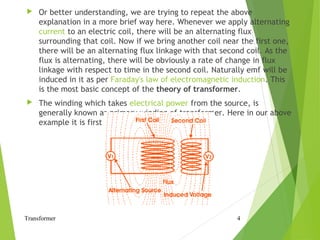

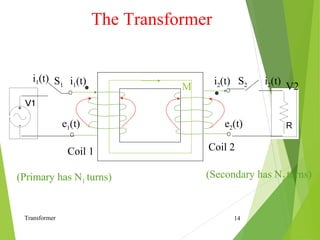
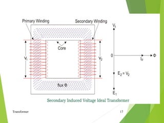
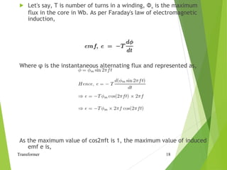
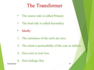
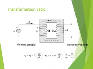
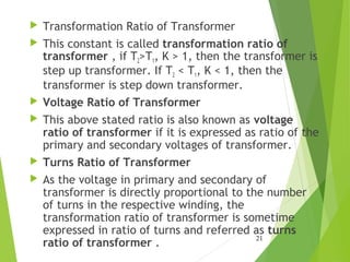
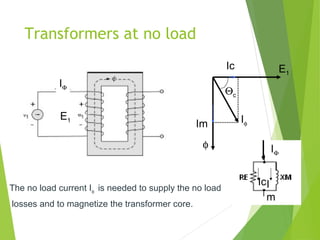
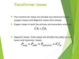
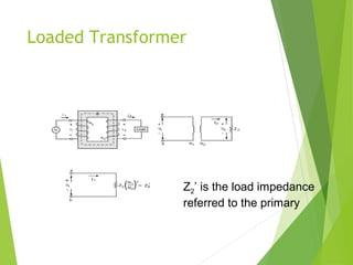
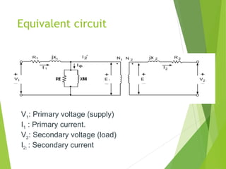
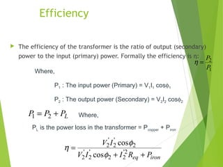

The document provides an in-depth explanation of electrical power transformers, detailing their definition, working principles based on Faraday's law of electromagnetic induction, and key components such as primary and secondary windings. It outlines the concept of mutual induction, how transformers modify voltage levels without altering frequency, and introduces the transformation ratio and efficiency calculations. Additionally, losses in transformers, including copper and magnetic losses, are discussed along with their impact on performance.


