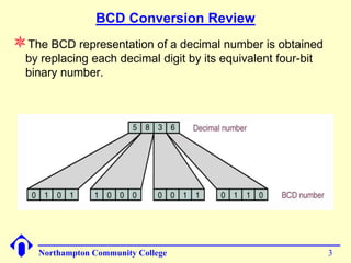
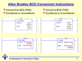
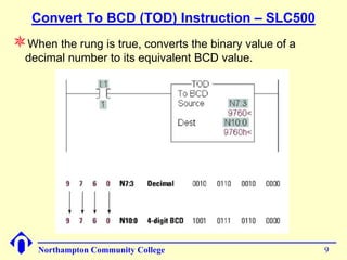
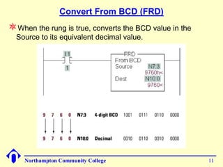
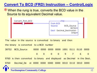
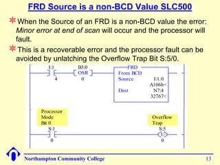
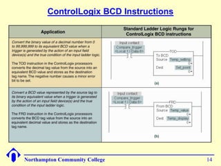
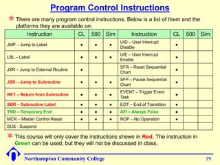
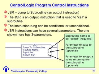
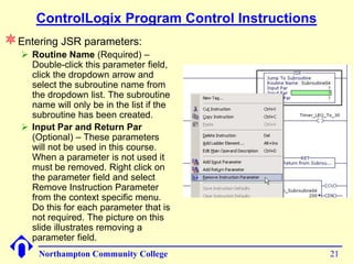
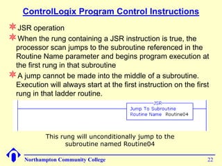
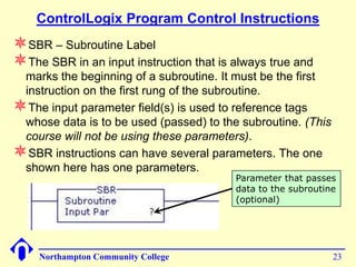
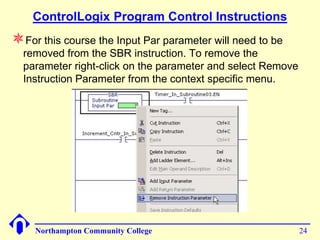
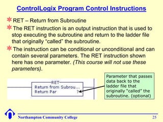
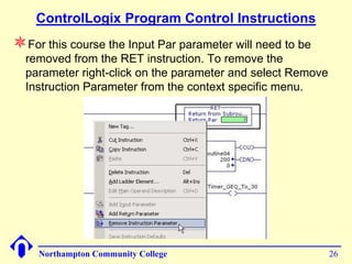
Conversion, Subroutines and
        Forcing I/O
       Chapter 07 and supplemental material
     Chapter 08 Sections 8-1, 8-2, 8-3-3 through
                       8-3-5


Northampton Community College                      1
Binary Coded Decimal (BCD) Review


Northampton Community College           2
BCD Conversion Review
The BCD representation of a decimal number is obtained
  by replacing each decimal digit by its equivalent four-bit
  binary number.


    Northampton Community College                              3
BCD Push Switch (Thumbwheel)


Northampton Community College         4
Push Switch (Thumbwheel) Truth Table


       Dial                     Bit Weight
     Position      8            4        2   1
         0         0            0        0   0
         1         0            0        0   1
         2         0            0        1   0
         3         0            0        1   1
         4         0            1        0   0
         5         0            1        0   1
         6         0            1        1   0
         7         0            1        1   1
         8         1            0        0   0
         9         1            0        0   1


Northampton Community College                    5
PLC Input Module Connections
              (BCD Input Device)


Northampton Community College          6
PLC Output Module Connections
           (BCD Output Device)


Northampton Community College         7
Allen Bradley BCD Conversion Instructions
Convert from BCD (FRD)                        Convert to BCD (TOD)
Conditional or Unconditional                  Conditional or Unconditional
               FRD                                             TOD
            From BCD                    0001               To BCD
            Source        I:1.0                            Source       N22:3
                         2437h<                                          1234<
            Dest          N7:4                             Dest          O:5.0
                          2437<                                         1234h<


                      FRD                                            TOD
              From BCD              1                        To BCD
              Source PushSw Right                            Source DspyOutValue
                          16#0000                                               0
              Dest   PushSw Value                            Dest   DisplayOutput
                                0                                        16#0000


     Northampton Community College                                                  8
Convert To BCD (TOD) Instruction – SLC500
When the rung is true, converts the binary value of a
  decimal number to its equivalent BCD value.


    Northampton Community College                        9
Convert To BCD (TOD) Instruction – ControlLogix
When the rung is true, converts the binary value of a
  decimal number to its equivalent BCD value.


  The decimal    value in the source is converted      to BCD binary       and then

  the binary is displayed      as the decimal   result in the destinatio n.

 9760     Decimal_So    urce        0     0       0     0     9        7       6      0

                                  0000 0000 0000 0000 1001 0111 0110 0000

 0000 0000 0000 0000 1001 0111 0110 0000 is then converted                      to decimal

 and displayed     as a Decimal    number     in the Dest.

 38752     BCD_Dest     0000 0000 0000 0000 1001 0111 0110 0000


      Northampton Community College                                                          10
Convert From BCD (FRD)
When the rung is true, converts the BCD value in the
  Source to its equivalent decimal value.


    Northampton Community College                       11
Convert To BCD (FRD) Instruction – ControlLogix
When the rung is true, converts the BCD value in the
  Source to its equivalent Decimal value.


 The value in the source is c onverted     to binary    and then

 the binary is c onverted   to a BCD number

 38752    BCD_Sourc e       0000 0000 0000 0000 1001 0111 0110 0000

                             0      0       0     0       9      7       6      0

 9760 is then c onverted    to binary   and displayed    as Dec imal   in the Dest.

 9760     Dec imal_De   st 0000 0000 0000 0000 0010 0110 0010 0000


        Northampton Community College                                               12
FRD Source is a non-BCD Value SLC500
When the Source of an FRD is a non-BCD value the error:
 Minor error at end of scan will occur and the processor will
 fault.
This is a recoverable error and the processor fault can be
 avoided by unlatching the Overflow Trap Bit S:5/0.
                I:1       B3:0            FRD
0000                      OSR          From BCD
                      4    0           Source      I:1.0
                                                  A106h<
                                       Dest        N7:4
                                                  32767<

             Processor
             Mode                                 Overflow
             Bit 0                                Trap
                 S:1                                 S:5
0001                                                  U
                 0                                    0


       Northampton Community College                            13
ControlLogix BCD Instructions


Northampton Community College           14
Subroutines

                       Chapter 08
                 Sections 8-3-3 to 8-3-5
                 Supplement Document


Northampton Community College              15
Subroutines
Subroutine(s) is a group of program code that performs a specific
 task. The subroutine(s) are part of a program (in our case the
 MainProgram) and are not part of the MainRoutine.
A subroutine can be invoked, (called), from anyplace in the
 MainRoutine or from another subroutine. When a subroutine is
 called from within another subroutine it is referred to as nesting
 subroutines.
Most, if not all, computer programs and PLC/PAC programs
 contain subroutines.
Subroutines are used to make what would be an enormous
 program more manageable by breaking up the code into smaller
 tasks. Specific functions within a task should be placed in
 subroutines.
Organizing a program by using subroutines makes the code
 easier to read, understand and maintain.
Subroutines can also be reused in other programs that require
 the same task be performed.


     Northampton Community College                                16
Subroutines
SLC500                              ControlLogix
The SLC500 uses                    The ControlLogix uses
 separate ladder files to            separate routines to store
 store and execute                   and execute subroutines.
 subroutines. There are a            The number of routines is
 total of 253 subroutine             limited to 32 per program.
 ladder files; #3 through
 #255.
                                    The MainRoutine is the
                                     main ladder routine and is
Ladder file #2 (LAD2) is            the one we have been
 the main ladder file and is         using in all labs to this
 the one we have been                date.
 using in all labs to this
 date.
                                    Scan starts at rung 0 in the
                                     MainRoutine and ends at
Scan starts at rung 0 LAD2          the End statement in the
 and ends at the End                 MainRoutine
 statement in LAD2.

    Northampton Community College                              17
Creating a ControlLogix Subroutine


1. To create a new subroutine right
click on MainProgram and select
New Routine… from the pop-up          2. New Routine dialog box will open.
menu                                  Type in the name of the subroutine
                                      and from the Type: dropdown,
                                      select the type of program code.
      3. The new
      subroutine will appear
      listed under the
      program that it was
      created in. Double
      click the subroutine to
      open the ladder
      editor.
     Northampton Community College                                    18
Program Control Instructions
 There are many program control instructions. Below is a list of them and the
    platforms they are available on:
         Instruction          CL 500 Sim            Instruction          CL   500 Sim
                                               UID – User Interrupt
JMP – Jump to Label              ●   ●    ●                              ●
                                               Disable
                                               UIE – User Interrupt
LBL – Label                      ●   ●    ●                              ●
                                               Enable
                                               SFR – Reset Sequential
JXR – Jump to External Routine   ●                                       ●
                                               Chart
                                               SFP – Pause Sequential
JSR – Jump to Subroutine         ●   ●    ●                              ●
                                               Chart
                                               EVENT – Trigger Event
RET – Return from Subroutine     ●   ●    ●                              ●
                                               Task
SBR – Subroutine Label           ●   ●    ●    EOT – End of Transition   ●
TND – Temporary End              ●   ●    ●    AFI – Always False        ●
MCR – Master Control Reset       ●   ●    ●    NOP – No Operation        ●
SUS - Suspend

 This course will only cover the instructions shown in Red. The instruction in
   Green can be used, but they will not be discussed in class.

        Northampton Community College                                              19
ControlLogix Program Control Instructions
JSR – Jump to Subroutine (an output instruction)
The JSR is an output instruction that is used to “call” a
 subroutine.
The instruction rung can be conditional or unconditional.
JSR instructions can have several parameters. The one
 shown here has 3-parameters.            Subroutine name to
                                           be “called” (required)

                                           Parameter to pass to
                                           the subroutine
                                           (optional)

                                           Parameter to accept a
                                           value returning from
                                           the subroutine
                                           (optional)

     Northampton Community College                                  20
ControlLogix Program Control Instructions
Entering JSR parameters:
    Routine Name (Required) –
     Double-click this parameter field,
     click the dropdown arrow and
     select the subroutine name from
     the dropdown list. The subroutine
     name will only be in the list if the
     subroutine has been created.
    Input Par and Return Par
     (Optional) – These parameters
     will not be used in this course.
     When a parameter is not used it
     must be removed. Right click on
     the parameter field and select
     Remove Instruction Parameter
     from the context specific menu.
     Do this for each parameter that is
     not required. The picture on this
     slide illustrates removing a
     parameter field.
       Northampton Community College              21
ControlLogix Program Control Instructions
JSR operation
When the rung containing a JSR instruction is true, the
 processor scan jumps to the subroutine referenced in the
 Routine Name parameter and begins program execution at
 the first rung in that subroutine
A jump cannot be made into the middle of a subroutine.
 Execution will always start at the first instruction on the first
 rung in that ladder routine.


            This rung will unconditionally jump to the
                   subroutine named Routine04

     Northampton Community College                               22
ControlLogix Program Control Instructions
SBR – Subroutine Label
The SBR in an input instruction that is always true and
 marks the beginning of a subroutine. It must be the first
 instruction on the first rung of the subroutine.
The input parameter field(s) is used to reference tags
 whose data is to be used (passed) to the subroutine. (This
 course will not be using these parameters).
SBR instructions can have several parameters. The one
 shown here has one parameters.
                                         Parameter that passes
                                         data to the subroutine
                                         (optional)


    Northampton Community College                             23
ControlLogix Program Control Instructions
For this course the Input Par parameter will need to be
  removed from the SBR instruction. To remove the
  parameter right-click on the parameter and select Remove
  Instruction Parameter from the context specific menu.


    Northampton Community College                            24
ControlLogix Program Control Instructions
RET – Return from Subroutine
The RET instruction is an output instruction that is used to
 stop executing the subroutine and return to the ladder file
 that originally “called” the subroutine.
The instruction can be conditional or unconditional and can
 contain several parameters. The RET instruction shown
 here has one parameter. (This course will not use these
 parameters).
                                         Parameter that passes
                                         data back to the
                                         ladder file that
                                         originally “called” the
                                         subroutine. (optional)


     Northampton Community College                                 25
ControlLogix Program Control Instructions
For this course the Input Par parameter will need to be
  removed from the RET instruction. To remove the
  parameter right-click on the parameter and select Remove
  Instruction Parameter from the context specific menu.


    Northampton Community College                            26
ControlLogix Program Control Instructions
Several conditional RET instructions can be present in a
  subroutine. As an example:
    If an RET instruction becomes true that is on rung 0006 in a
     subroutine containing 45-rungs, the program scan will return to the
     ladder file that originally called the subroutine and rungs 0007
     through 0045 will not execute.
    If the RET instruction on rung 0006 becomes false another RET
     instruction becomes true that is on rung 0010 in the same
     subroutine, the program scan will return to the ladder file that
     originally called the subroutine and rungs 0011 through 0045 will not
     executed.
If the entire subroutine ladder file is to be always scanned,
  placing a RET instruction on the last rung of the program is
  optional. If an RET instruction is not found in the subroutine
  ladder file, the END statement performs the return.

     Northampton Community College                                      27
Program Execution using Subroutines


Northampton Community College           28
Forcing I/O


Northampton Community College    29
Using the Force I/O Function
The force function will only work on field I/O devices,
 therefore the input and output data files in the SLC500 and
 the Controller tags in the ControlLogix.
Before applying a force to any input or any output device,
 an understanding of the potential effect that force(s) will
 have on the machine or process operation and to the safety
 of personal is essential.
          DO NOT INSTALL FORCES WITHOUT FIRST
     UNDERSTANDING WHAT AFFECT IT WILL HAVE ON
       THE OPERATION OF THE MACHINE OR PROCESS
Most programming software provide some visible means of
 alerting the user that a force is in affect or installed.
Most processor modules have an LED indicator that will be
 lit if there are any forces installed.

     Northampton Community College                         30
Installing and Enabling Forces
This is an instructor led, interactive lab.
If there is no program running in the PLC at your
 workstation, open a program that uses I/O field devices,
 download the program to the PLC, then place the PLC in
 RUN mode.
Your instructor will also switch to RSLogix and attach to
 someone’s workstation to lead you through and
 demonstrate the force functions.


    Northampton Community College                            31

00 chapter07 and_08_conversion_subroutines_force_sp13

  • 1.
    Conversion, Subroutines and Forcing I/O Chapter 07 and supplemental material Chapter 08 Sections 8-1, 8-2, 8-3-3 through 8-3-5 Northampton Community College 1
  • 2.
    Binary Coded Decimal(BCD) Review Northampton Community College 2
  • 3.
    BCD Conversion Review TheBCD representation of a decimal number is obtained by replacing each decimal digit by its equivalent four-bit binary number. Northampton Community College 3
  • 4.
    BCD Push Switch(Thumbwheel) Northampton Community College 4
  • 5.
    Push Switch (Thumbwheel)Truth Table Dial Bit Weight Position 8 4 2 1 0 0 0 0 0 1 0 0 0 1 2 0 0 1 0 3 0 0 1 1 4 0 1 0 0 5 0 1 0 1 6 0 1 1 0 7 0 1 1 1 8 1 0 0 0 9 1 0 0 1 Northampton Community College 5
  • 6.
    PLC Input ModuleConnections (BCD Input Device) Northampton Community College 6
  • 7.
    PLC Output ModuleConnections (BCD Output Device) Northampton Community College 7
  • 8.
    Allen Bradley BCDConversion Instructions Convert from BCD (FRD) Convert to BCD (TOD) Conditional or Unconditional Conditional or Unconditional FRD TOD From BCD 0001 To BCD Source I:1.0 Source N22:3 2437h< 1234< Dest N7:4 Dest O:5.0 2437< 1234h< FRD TOD From BCD 1 To BCD Source PushSw Right Source DspyOutValue 16#0000 0 Dest PushSw Value Dest DisplayOutput 0 16#0000 Northampton Community College 8
  • 9.
    Convert To BCD(TOD) Instruction – SLC500 When the rung is true, converts the binary value of a decimal number to its equivalent BCD value. Northampton Community College 9
  • 10.
    Convert To BCD(TOD) Instruction – ControlLogix When the rung is true, converts the binary value of a decimal number to its equivalent BCD value. The decimal value in the source is converted to BCD binary and then the binary is displayed as the decimal result in the destinatio n. 9760 Decimal_So urce 0 0 0 0 9 7 6 0 0000 0000 0000 0000 1001 0111 0110 0000 0000 0000 0000 0000 1001 0111 0110 0000 is then converted to decimal and displayed as a Decimal number in the Dest. 38752 BCD_Dest 0000 0000 0000 0000 1001 0111 0110 0000 Northampton Community College 10
  • 11.
    Convert From BCD(FRD) When the rung is true, converts the BCD value in the Source to its equivalent decimal value. Northampton Community College 11
  • 12.
    Convert To BCD(FRD) Instruction – ControlLogix When the rung is true, converts the BCD value in the Source to its equivalent Decimal value. The value in the source is c onverted to binary and then the binary is c onverted to a BCD number 38752 BCD_Sourc e 0000 0000 0000 0000 1001 0111 0110 0000 0 0 0 0 9 7 6 0 9760 is then c onverted to binary and displayed as Dec imal in the Dest. 9760 Dec imal_De st 0000 0000 0000 0000 0010 0110 0010 0000 Northampton Community College 12
  • 13.
    FRD Source isa non-BCD Value SLC500 When the Source of an FRD is a non-BCD value the error: Minor error at end of scan will occur and the processor will fault. This is a recoverable error and the processor fault can be avoided by unlatching the Overflow Trap Bit S:5/0. I:1 B3:0 FRD 0000 OSR From BCD 4 0 Source I:1.0 A106h< Dest N7:4 32767< Processor Mode Overflow Bit 0 Trap S:1 S:5 0001 U 0 0 Northampton Community College 13
  • 14.
  • 15.
    Subroutines Chapter 08 Sections 8-3-3 to 8-3-5 Supplement Document Northampton Community College 15
  • 16.
    Subroutines Subroutine(s) is agroup of program code that performs a specific task. The subroutine(s) are part of a program (in our case the MainProgram) and are not part of the MainRoutine. A subroutine can be invoked, (called), from anyplace in the MainRoutine or from another subroutine. When a subroutine is called from within another subroutine it is referred to as nesting subroutines. Most, if not all, computer programs and PLC/PAC programs contain subroutines. Subroutines are used to make what would be an enormous program more manageable by breaking up the code into smaller tasks. Specific functions within a task should be placed in subroutines. Organizing a program by using subroutines makes the code easier to read, understand and maintain. Subroutines can also be reused in other programs that require the same task be performed. Northampton Community College 16
  • 17.
    Subroutines SLC500 ControlLogix The SLC500 uses The ControlLogix uses separate ladder files to separate routines to store store and execute and execute subroutines. subroutines. There are a The number of routines is total of 253 subroutine limited to 32 per program. ladder files; #3 through #255. The MainRoutine is the main ladder routine and is Ladder file #2 (LAD2) is the one we have been the main ladder file and is using in all labs to this the one we have been date. using in all labs to this date. Scan starts at rung 0 in the MainRoutine and ends at Scan starts at rung 0 LAD2 the End statement in the and ends at the End MainRoutine statement in LAD2. Northampton Community College 17
  • 18.
    Creating a ControlLogixSubroutine 1. To create a new subroutine right click on MainProgram and select New Routine… from the pop-up 2. New Routine dialog box will open. menu Type in the name of the subroutine and from the Type: dropdown, select the type of program code. 3. The new subroutine will appear listed under the program that it was created in. Double click the subroutine to open the ladder editor. Northampton Community College 18
  • 19.
    Program Control Instructions There are many program control instructions. Below is a list of them and the platforms they are available on: Instruction CL 500 Sim Instruction CL 500 Sim UID – User Interrupt JMP – Jump to Label ● ● ● ● Disable UIE – User Interrupt LBL – Label ● ● ● ● Enable SFR – Reset Sequential JXR – Jump to External Routine ● ● Chart SFP – Pause Sequential JSR – Jump to Subroutine ● ● ● ● Chart EVENT – Trigger Event RET – Return from Subroutine ● ● ● ● Task SBR – Subroutine Label ● ● ● EOT – End of Transition ● TND – Temporary End ● ● ● AFI – Always False ● MCR – Master Control Reset ● ● ● NOP – No Operation ● SUS - Suspend  This course will only cover the instructions shown in Red. The instruction in Green can be used, but they will not be discussed in class. Northampton Community College 19
  • 20.
    ControlLogix Program ControlInstructions JSR – Jump to Subroutine (an output instruction) The JSR is an output instruction that is used to “call” a subroutine. The instruction rung can be conditional or unconditional. JSR instructions can have several parameters. The one shown here has 3-parameters. Subroutine name to be “called” (required) Parameter to pass to the subroutine (optional) Parameter to accept a value returning from the subroutine (optional) Northampton Community College 20
  • 21.
    ControlLogix Program ControlInstructions Entering JSR parameters:  Routine Name (Required) – Double-click this parameter field, click the dropdown arrow and select the subroutine name from the dropdown list. The subroutine name will only be in the list if the subroutine has been created.  Input Par and Return Par (Optional) – These parameters will not be used in this course. When a parameter is not used it must be removed. Right click on the parameter field and select Remove Instruction Parameter from the context specific menu. Do this for each parameter that is not required. The picture on this slide illustrates removing a parameter field. Northampton Community College 21
  • 22.
    ControlLogix Program ControlInstructions JSR operation When the rung containing a JSR instruction is true, the processor scan jumps to the subroutine referenced in the Routine Name parameter and begins program execution at the first rung in that subroutine A jump cannot be made into the middle of a subroutine. Execution will always start at the first instruction on the first rung in that ladder routine. This rung will unconditionally jump to the subroutine named Routine04 Northampton Community College 22
  • 23.
    ControlLogix Program ControlInstructions SBR – Subroutine Label The SBR in an input instruction that is always true and marks the beginning of a subroutine. It must be the first instruction on the first rung of the subroutine. The input parameter field(s) is used to reference tags whose data is to be used (passed) to the subroutine. (This course will not be using these parameters). SBR instructions can have several parameters. The one shown here has one parameters. Parameter that passes data to the subroutine (optional) Northampton Community College 23
  • 24.
    ControlLogix Program ControlInstructions For this course the Input Par parameter will need to be removed from the SBR instruction. To remove the parameter right-click on the parameter and select Remove Instruction Parameter from the context specific menu. Northampton Community College 24
  • 25.
    ControlLogix Program ControlInstructions RET – Return from Subroutine The RET instruction is an output instruction that is used to stop executing the subroutine and return to the ladder file that originally “called” the subroutine. The instruction can be conditional or unconditional and can contain several parameters. The RET instruction shown here has one parameter. (This course will not use these parameters). Parameter that passes data back to the ladder file that originally “called” the subroutine. (optional) Northampton Community College 25
  • 26.
    ControlLogix Program ControlInstructions For this course the Input Par parameter will need to be removed from the RET instruction. To remove the parameter right-click on the parameter and select Remove Instruction Parameter from the context specific menu. Northampton Community College 26
  • 27.
    ControlLogix Program ControlInstructions Several conditional RET instructions can be present in a subroutine. As an example:  If an RET instruction becomes true that is on rung 0006 in a subroutine containing 45-rungs, the program scan will return to the ladder file that originally called the subroutine and rungs 0007 through 0045 will not execute.  If the RET instruction on rung 0006 becomes false another RET instruction becomes true that is on rung 0010 in the same subroutine, the program scan will return to the ladder file that originally called the subroutine and rungs 0011 through 0045 will not executed. If the entire subroutine ladder file is to be always scanned, placing a RET instruction on the last rung of the program is optional. If an RET instruction is not found in the subroutine ladder file, the END statement performs the return. Northampton Community College 27
  • 28.
    Program Execution usingSubroutines Northampton Community College 28
  • 29.
  • 30.
    Using the ForceI/O Function The force function will only work on field I/O devices, therefore the input and output data files in the SLC500 and the Controller tags in the ControlLogix. Before applying a force to any input or any output device, an understanding of the potential effect that force(s) will have on the machine or process operation and to the safety of personal is essential. DO NOT INSTALL FORCES WITHOUT FIRST UNDERSTANDING WHAT AFFECT IT WILL HAVE ON THE OPERATION OF THE MACHINE OR PROCESS Most programming software provide some visible means of alerting the user that a force is in affect or installed. Most processor modules have an LED indicator that will be lit if there are any forces installed. Northampton Community College 30
  • 31.
    Installing and EnablingForces This is an instructor led, interactive lab. If there is no program running in the PLC at your workstation, open a program that uses I/O field devices, download the program to the PLC, then place the PLC in RUN mode. Your instructor will also switch to RSLogix and attach to someone’s workstation to lead you through and demonstrate the force functions. Northampton Community College 31