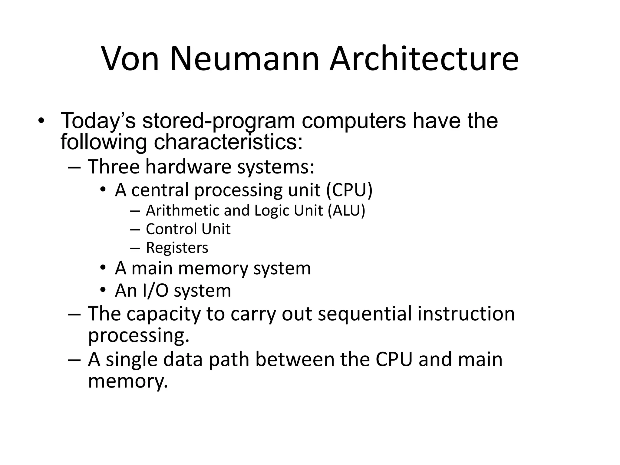
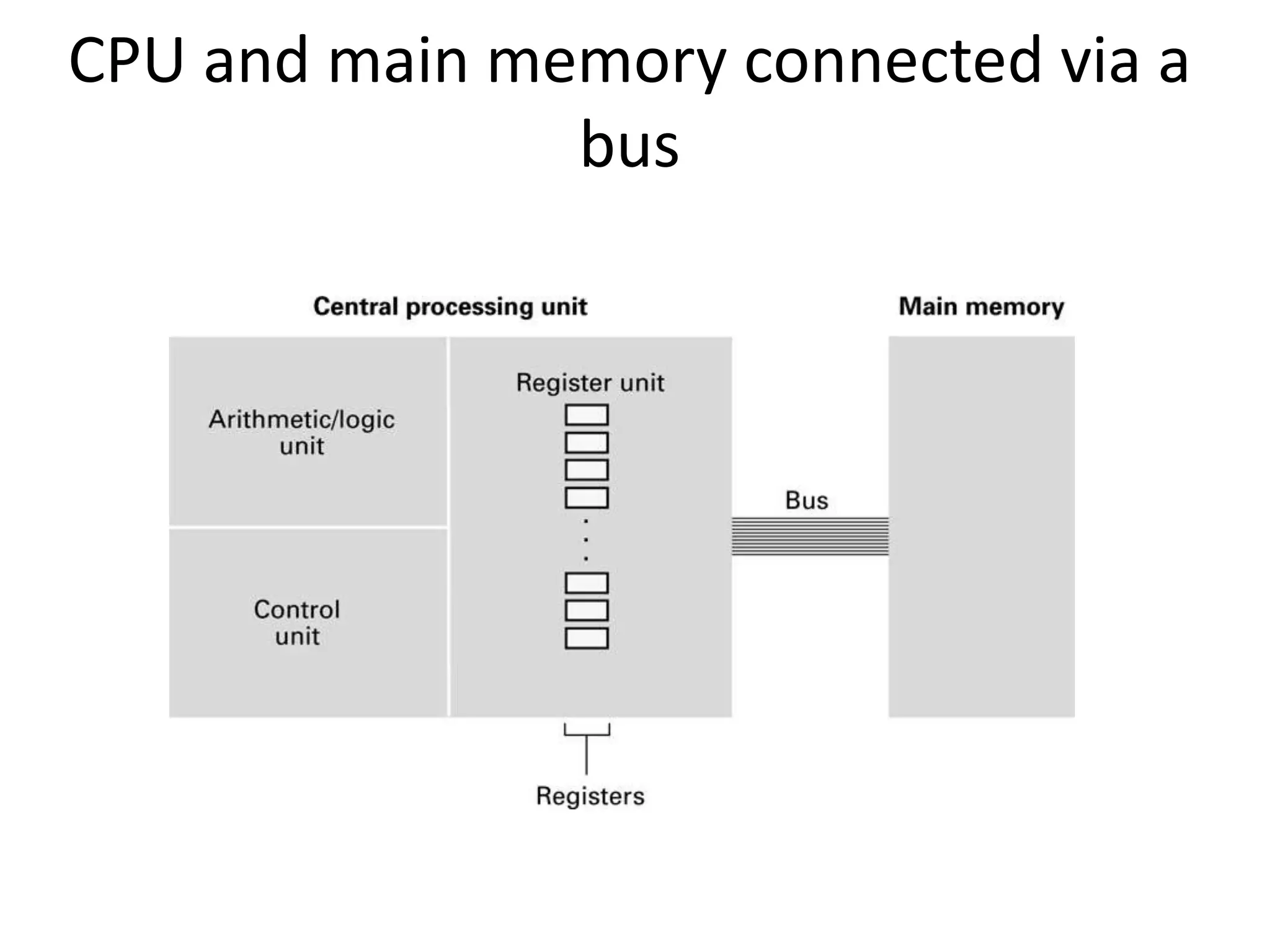
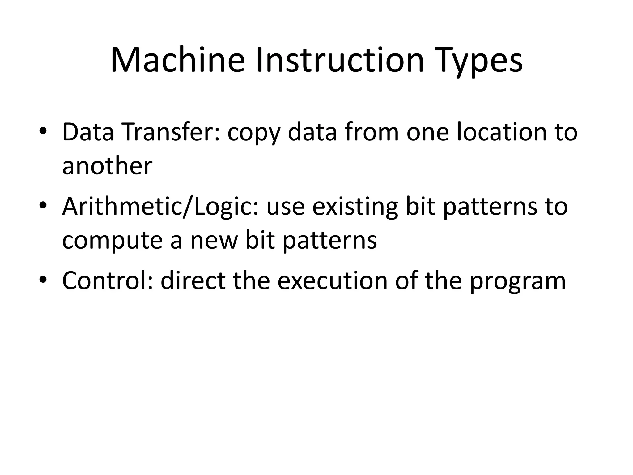
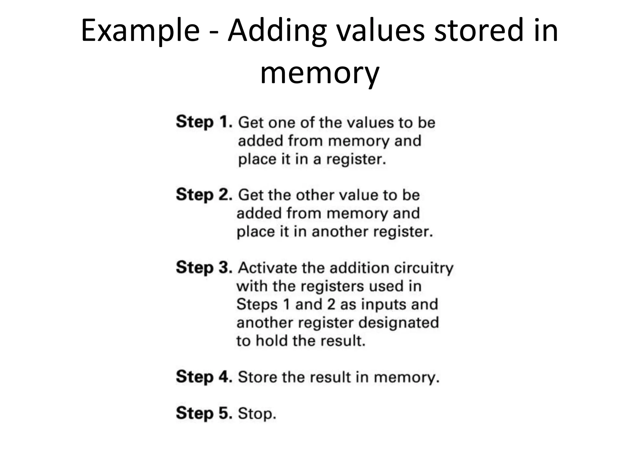
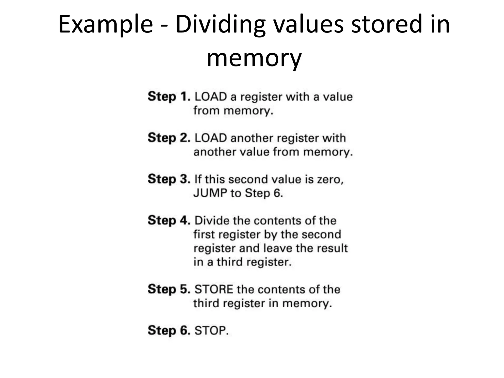
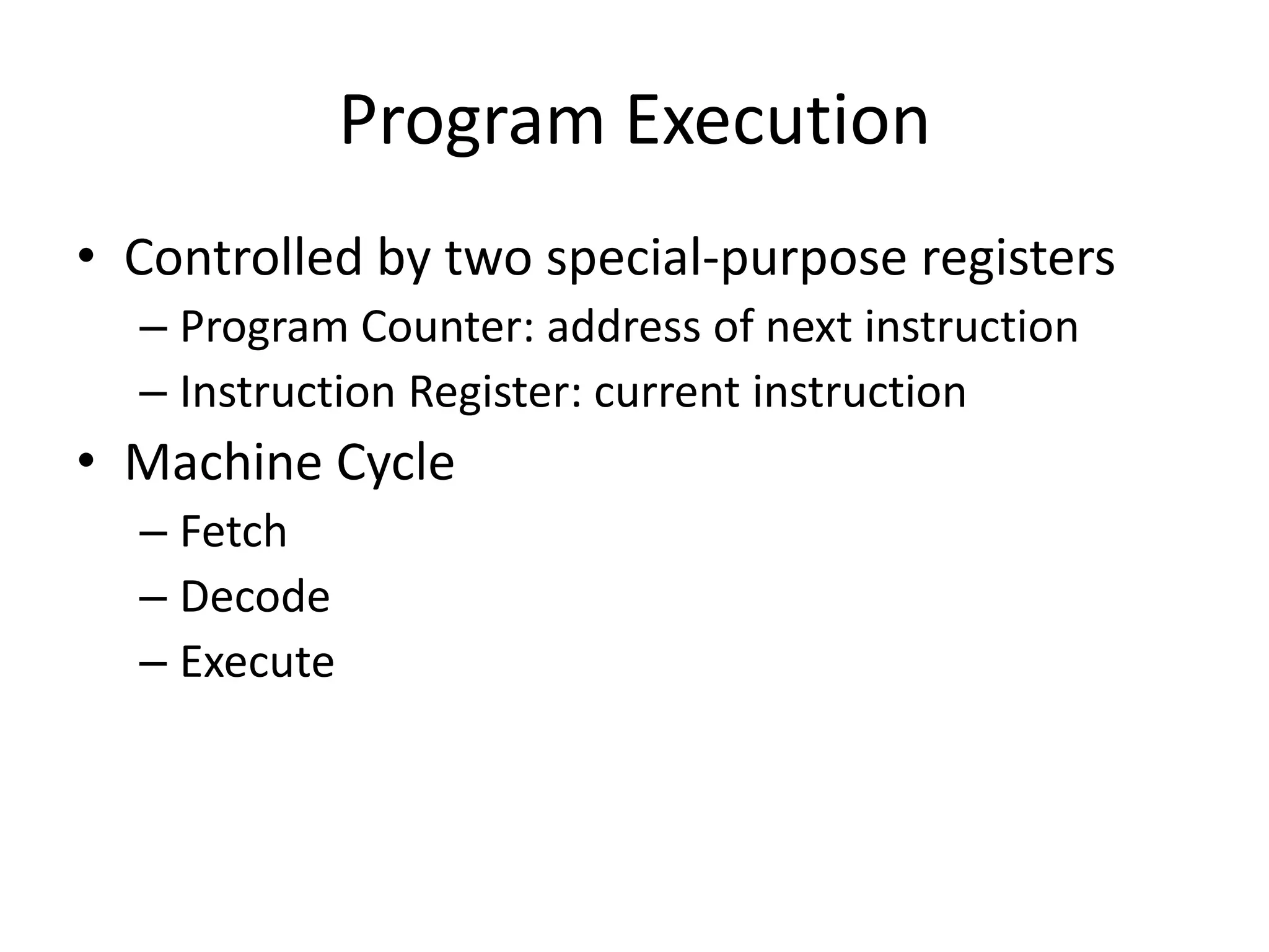
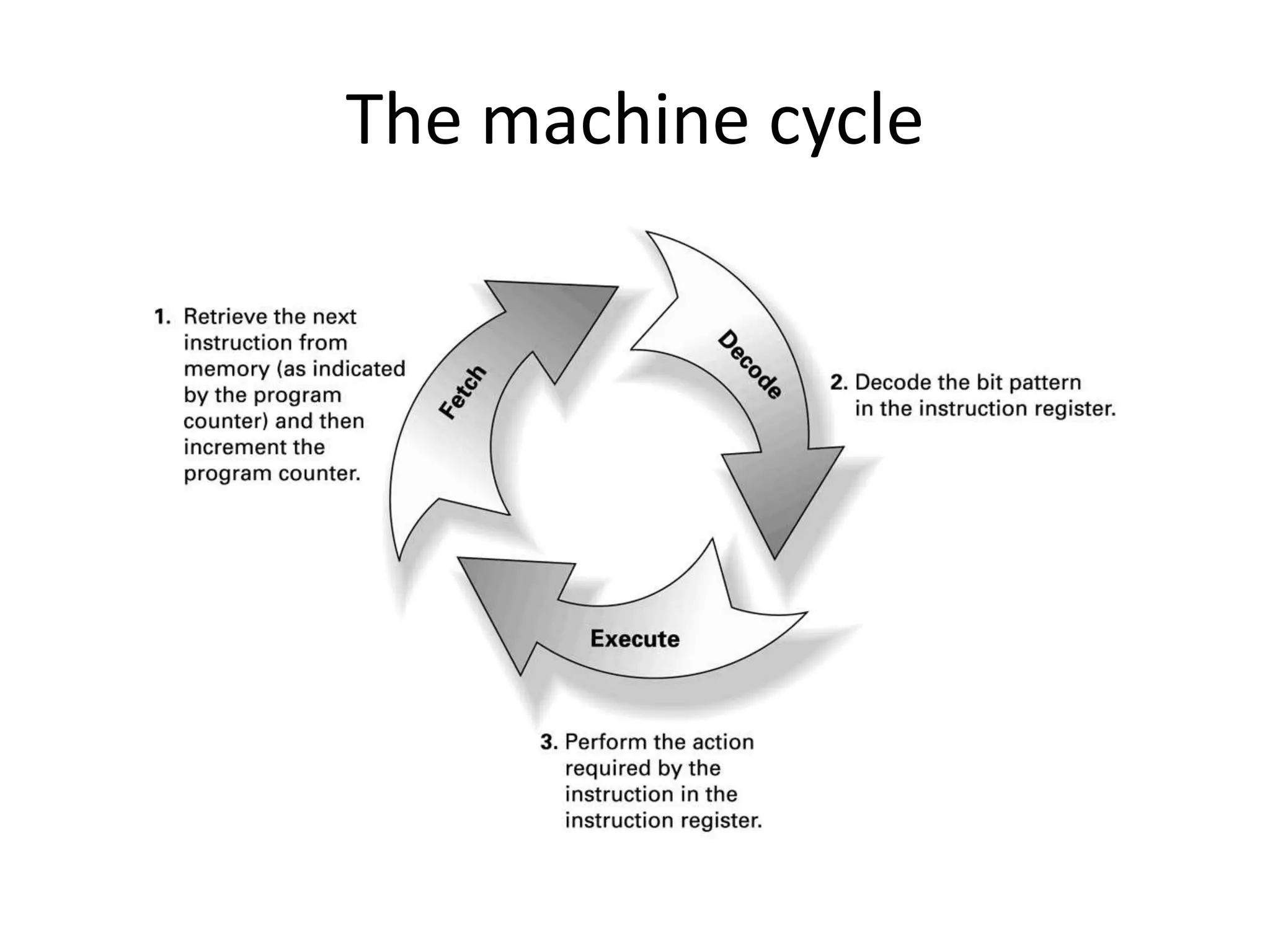
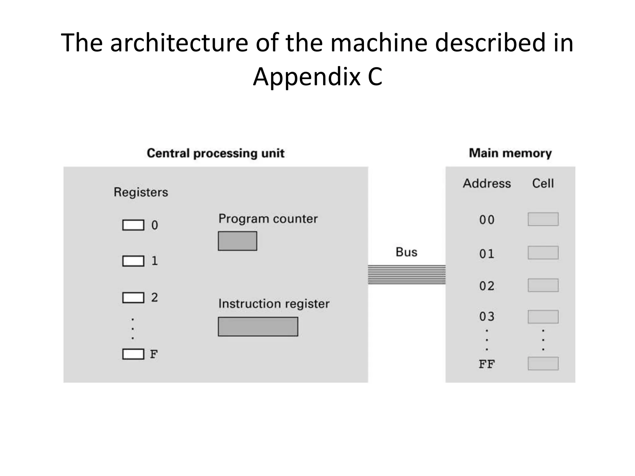
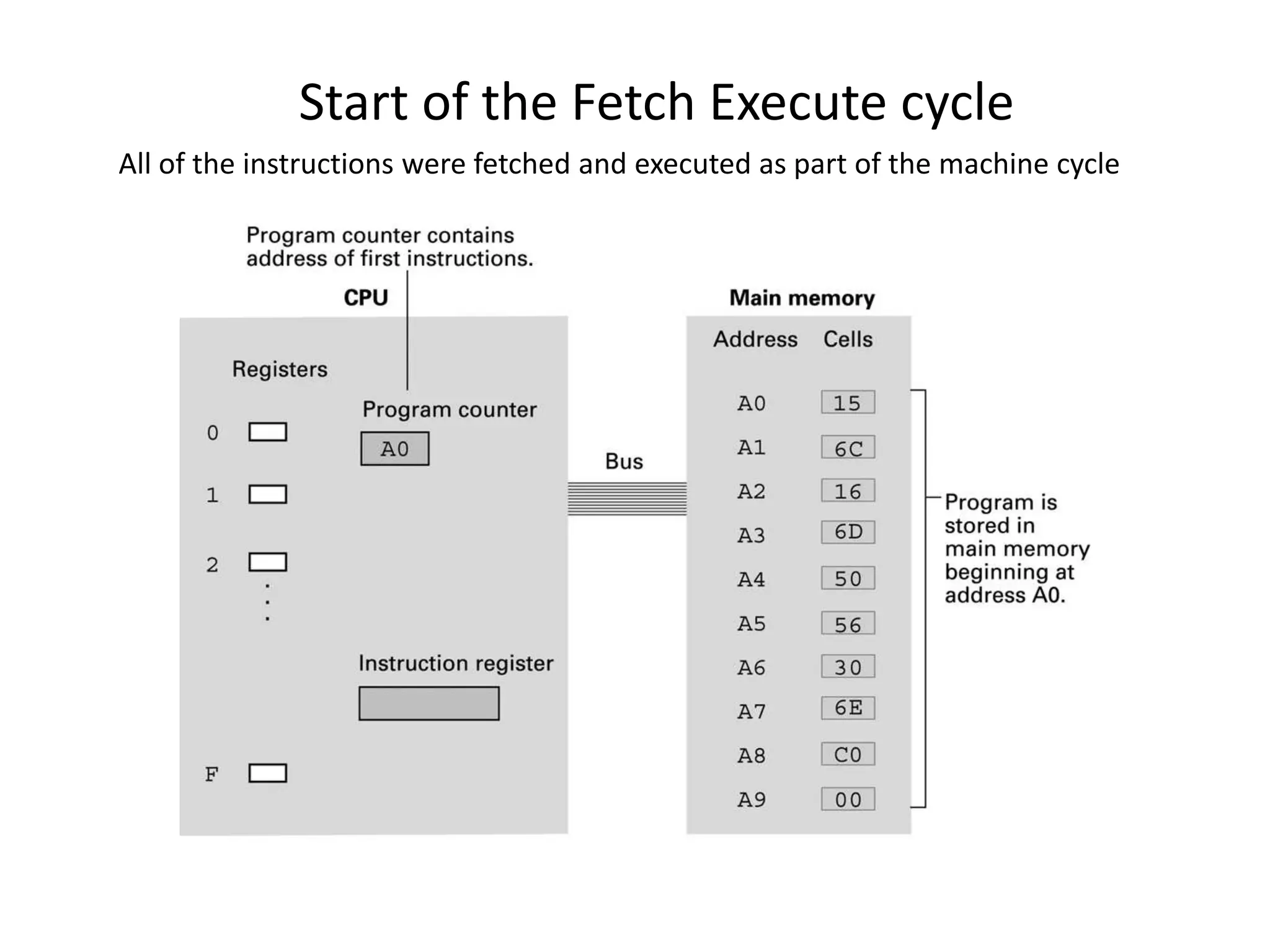
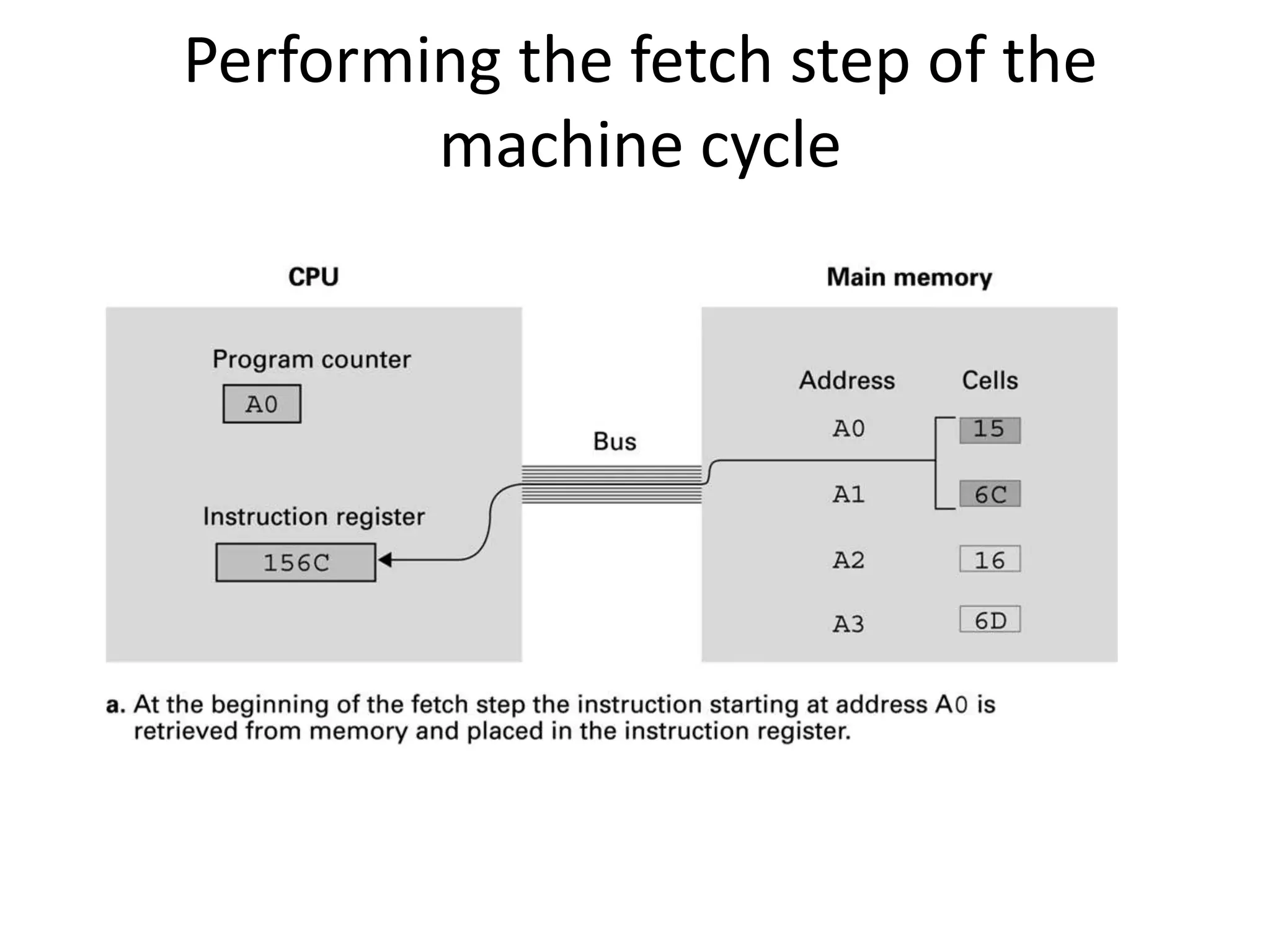
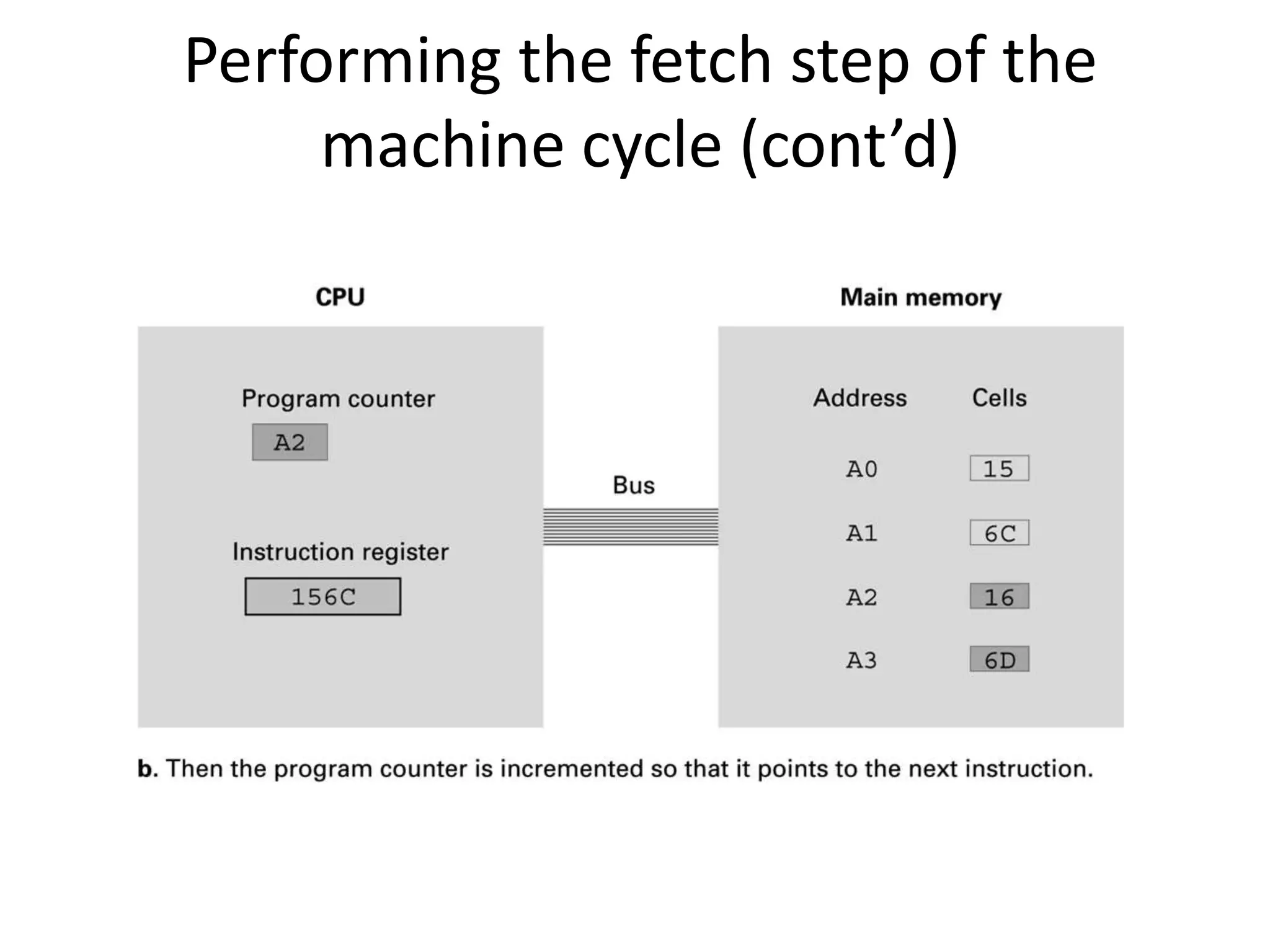
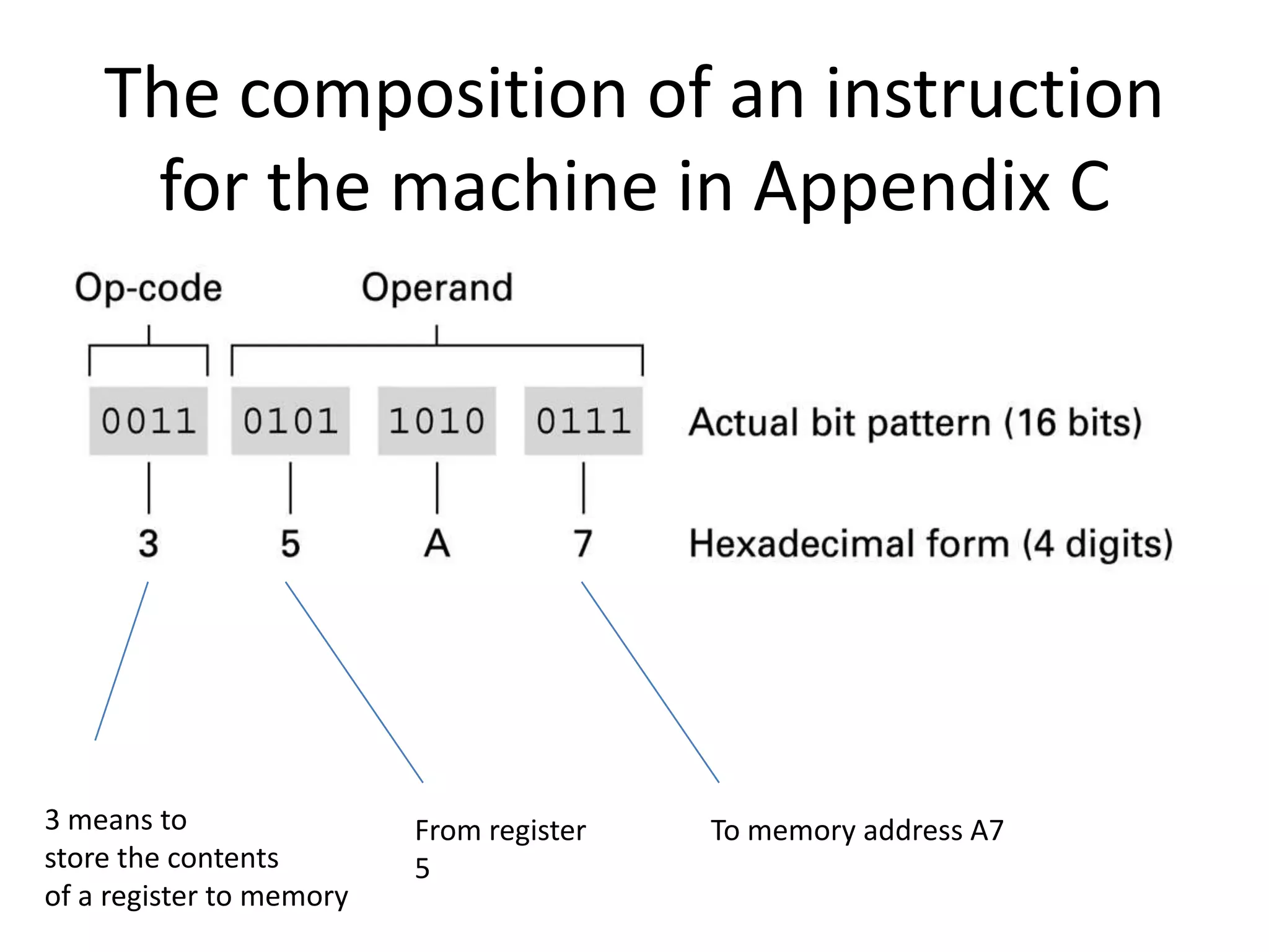
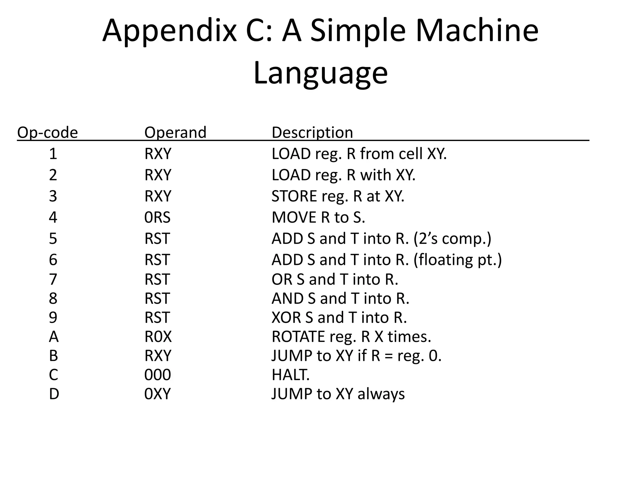
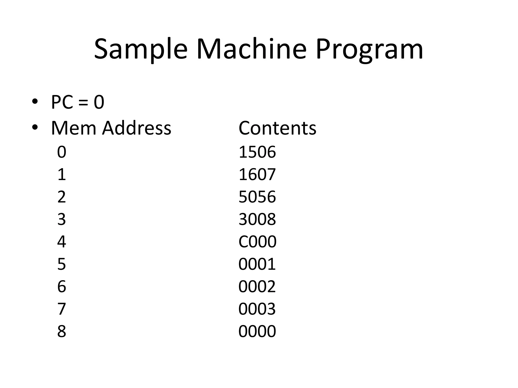
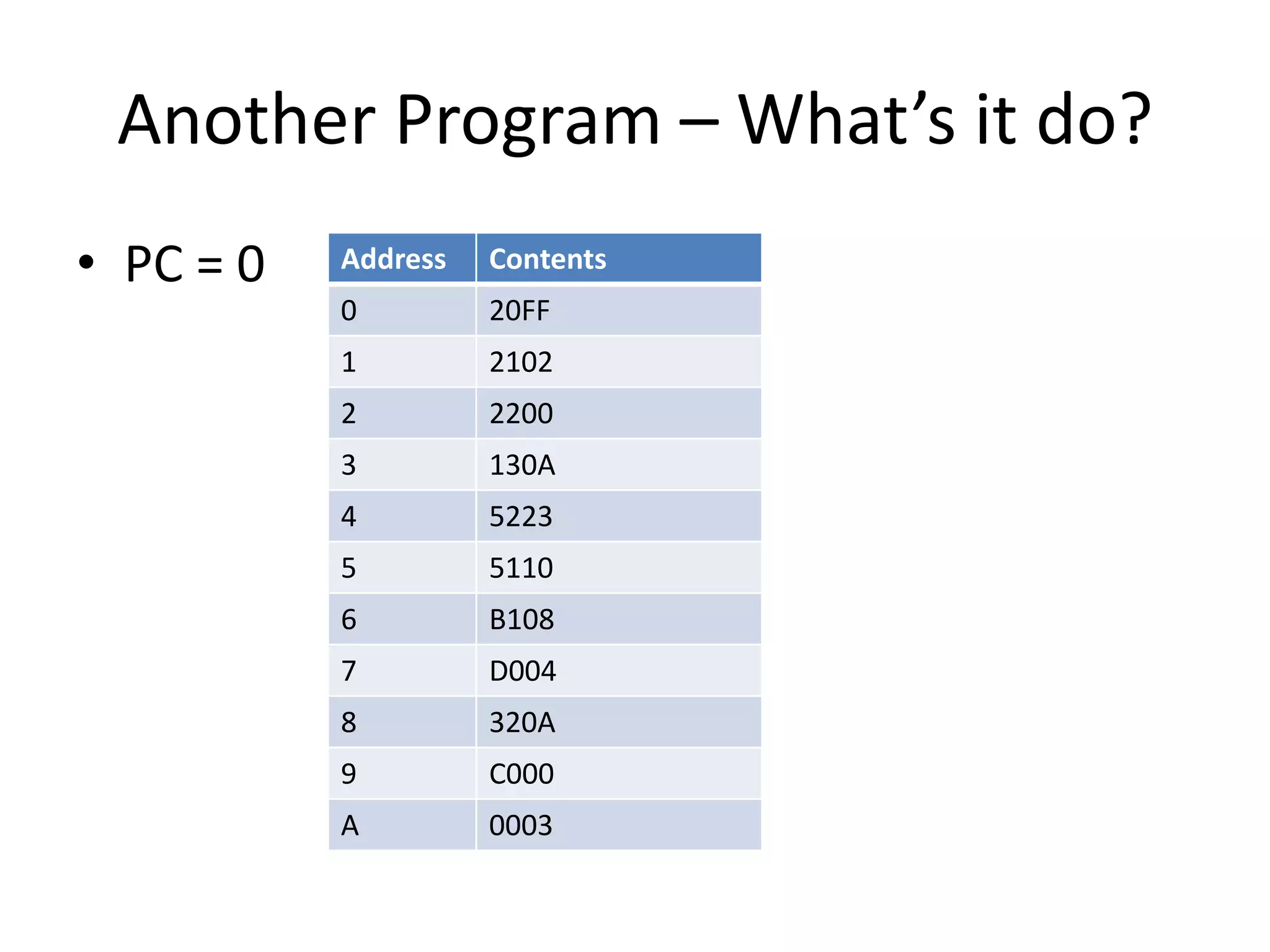
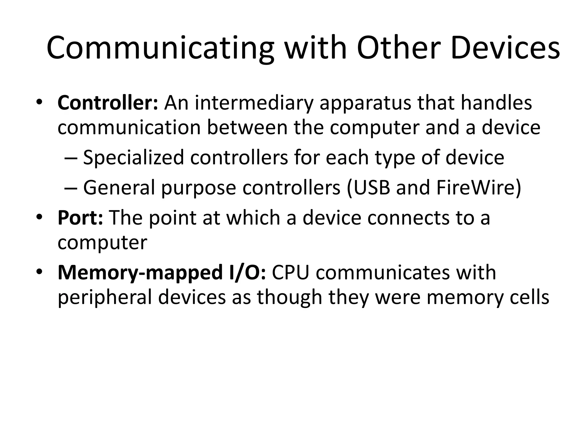
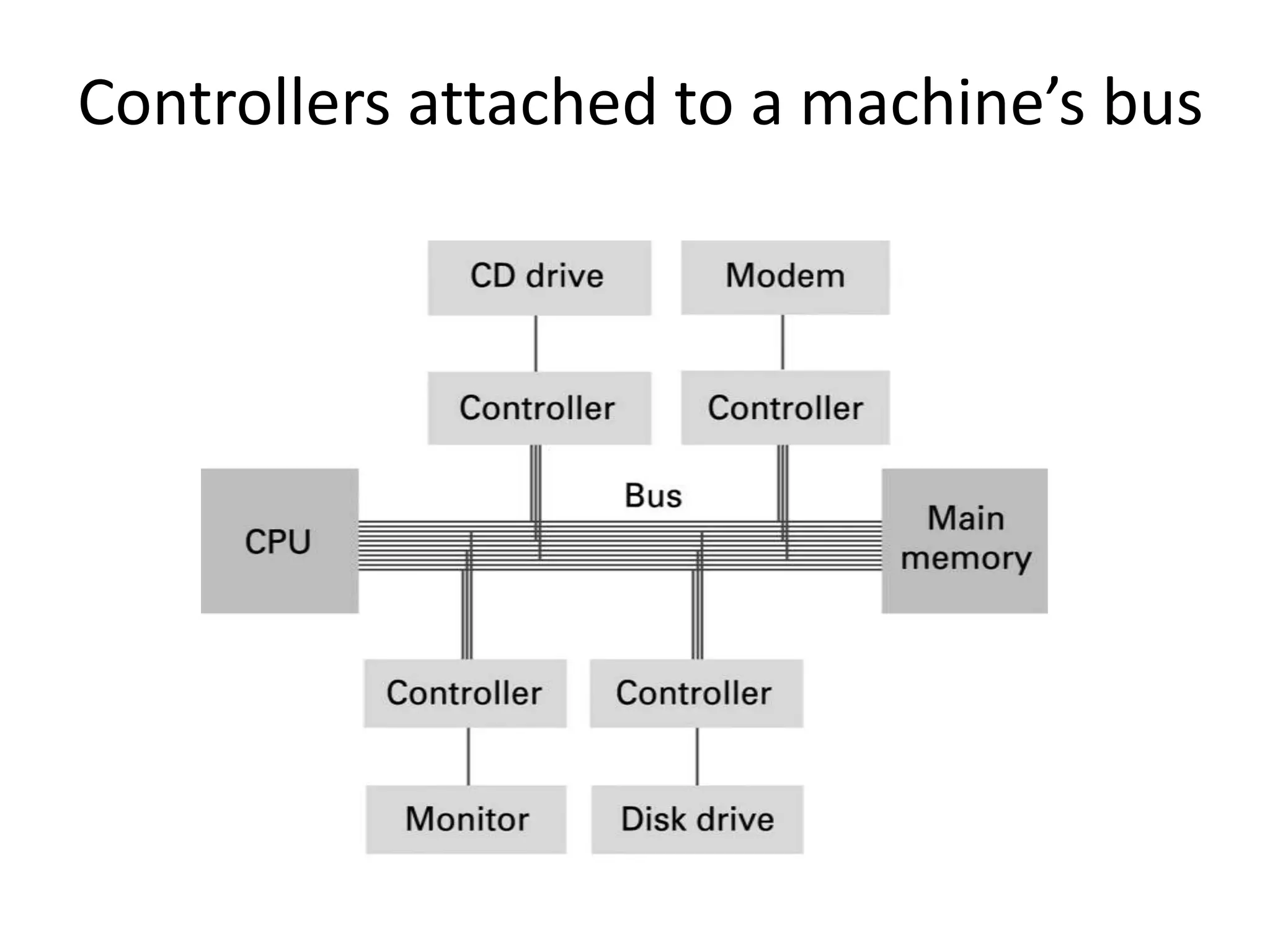
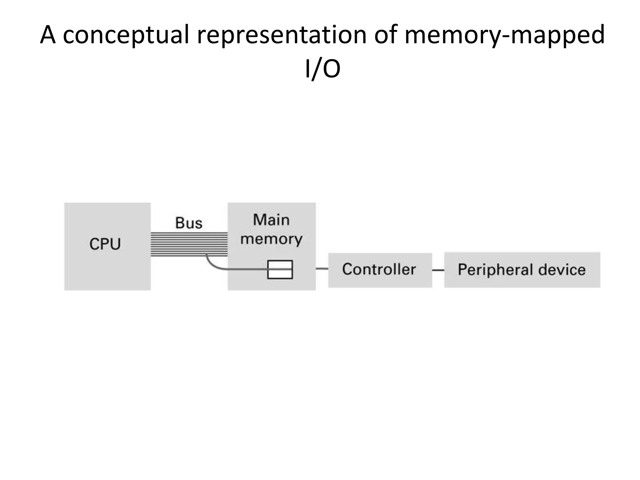
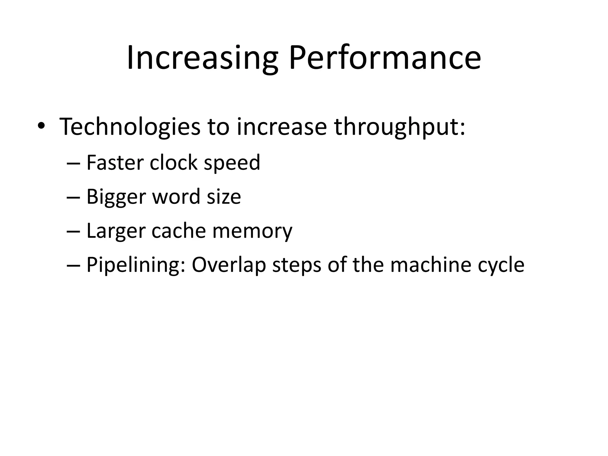
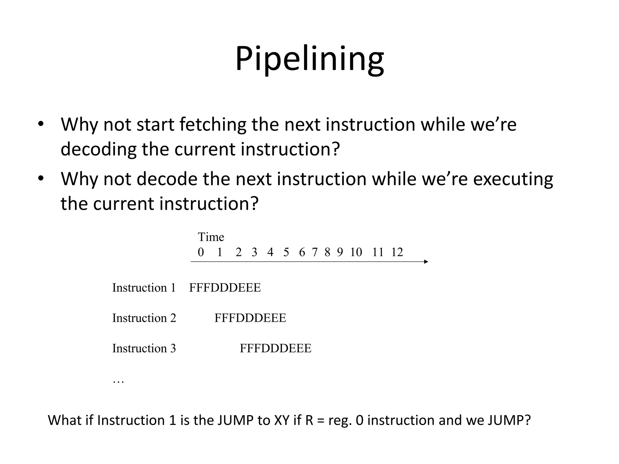
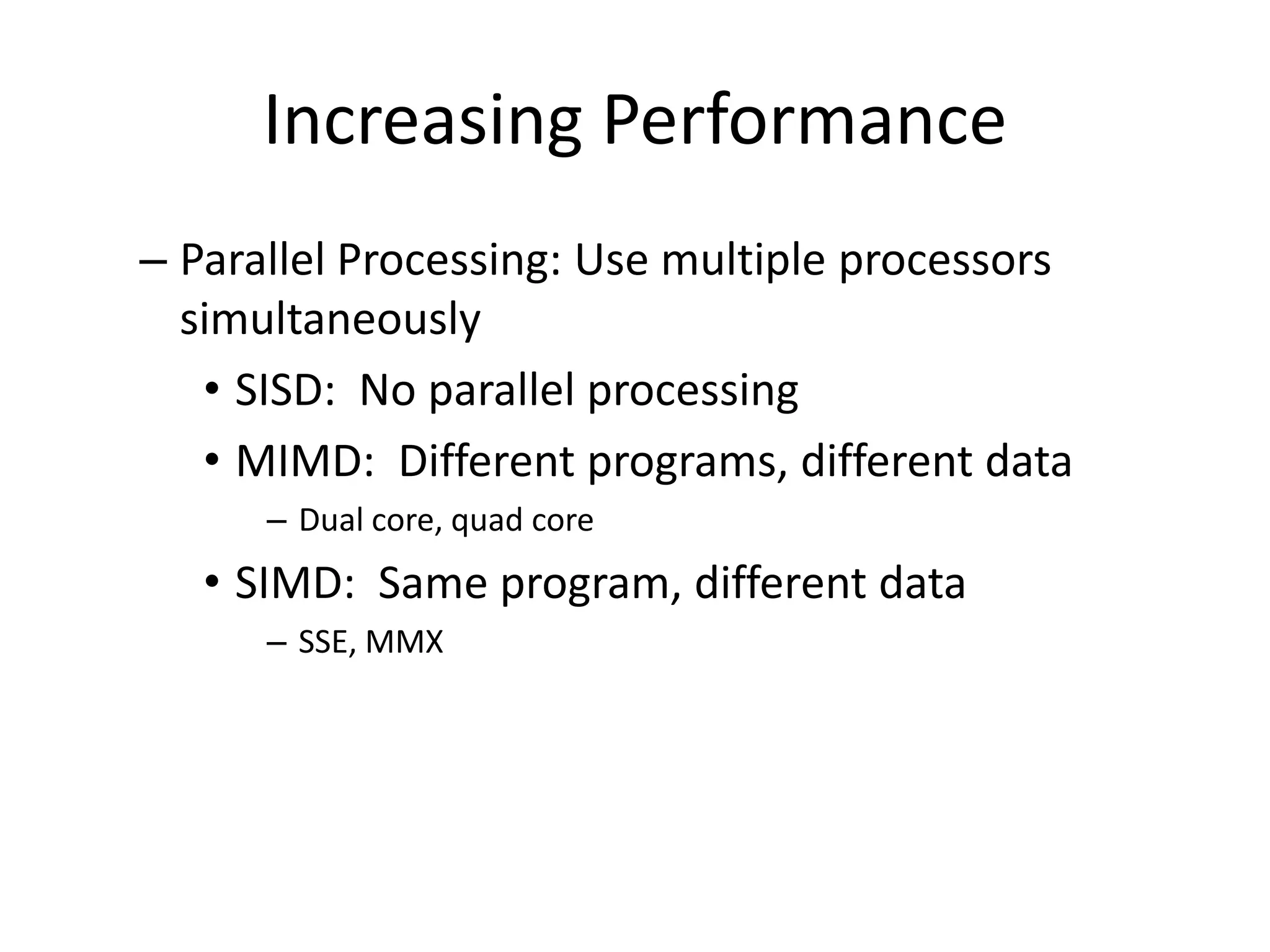
Computer Architecture and Data
       Manipulation
           Chapter 3
Von Neumann Architecture
• Today’s stored-program computers have the
  following characteristics:
   – Three hardware systems:
     • A central processing unit (CPU)
        – Arithmetic and Logic Unit (ALU)
        – Control Unit
        – Registers
     • A main memory system
     • An I/O system
  – The capacity to carry out sequential instruction
    processing.
  – A single data path between the CPU and main
    memory.
CPU and main memory connected via a
               bus
Stored Program Concept
A program can be encoded as bit patterns and
stored in main memory. From there, the CPU
can then extract the instructions and execute
them. In turn, the program to be executed can
be altered easily.
Terminology
• Machine instruction: An instruction (or
  command) encoded as a bit pattern
  recognizable by the CPU
• Machine language: The set of all instructions
  recognized by a machine
Machine Language Philosophies
• Reduced Instruction Set Computing (RISC)
  – Few, simple, efficient, and fast instructions
  – Examples: PowerPC from Apple/IBM/Motorola
               and SPARC from Sun Microsystems
• Complex Instruction Set Computing (CISC)
  – Many, convenient, and powerful instructions
  – Example: Pentium from Intel
Machine Instruction Types
• Data Transfer: copy data from one location to
  another
• Arithmetic/Logic: use existing bit patterns to
  compute a new bit patterns
• Control: direct the execution of the program
Example - Adding values stored in
            memory
Example - Dividing values stored in
             memory
Program Execution
• Controlled by two special-purpose registers
  – Program Counter: address of next instruction
  – Instruction Register: current instruction
• Machine Cycle
  – Fetch
  – Decode
  – Execute
The machine cycle
Program Execution
• Controlled by two special-purpose registers
  – Program counter: address of next instruction
  – Instruction register: current instruction
• Machine Cycle
  – Fetch
  – Decode
  – Execute
The architecture of the machine described in
                 Appendix C
Start of the Fetch Execute cycle
All of the instructions were fetched and executed as part of the machine cycle
Performing the fetch step of the
        machine cycle
Performing the fetch step of the
     machine cycle (cont’d)
Parts of a Machine Instruction
• Op-code: Specifies which operation to execute
• Operand: Gives more detailed information
  about the operation
  – Interpretation of operand varies depending on op-
    code
The composition of an instruction
     for the machine in Appendix C


3 means to                From register   To memory address A7
store the contents        5
of a register to memory
Appendix C: A Simple Machine
                   Language
Op-code     Operand   Description
    1       RXY       LOAD reg. R from cell XY.
    2       RXY       LOAD reg. R with XY.
    3       RXY       STORE reg. R at XY.
    4       0RS       MOVE R to S.
    5       RST       ADD S and T into R. (2’s comp.)
    6       RST       ADD S and T into R. (floating pt.)
    7       RST       OR S and T into R.
    8       RST       AND S and T into R.
    9       RST       XOR S and T into R.
    A       R0X       ROTATE reg. R X times.
    B       RXY       JUMP to XY if R = reg. 0.
    C       000       HALT.
    D       0XY       JUMP to XY always
Sample Machine Program
• PC = 0
• Mem Address   Contents
  0             1506
  1             1607
  2             5056
  3             3008
  4             C000
  5             0001
  6             0002
  7             0003
  8             0000
Exercise
• PC = 0
• Write a program that subtracts 1 from the
  value in memory address FF
Another Program – What’s it do?
• PC = 0   Address   Contents
           0         20FF
           1         2102
           2         2200
           3         130A
           4         5223
           5         5110
           6         B108
           7         D004
           8         320A
           9         C000
           A         0003
Exercise
• Write a program that computes the opposite
  of the value in memory address FF
  – E.g. if the value is +5 then it becomes -5
Communicating with Other Devices
• Controller: An intermediary apparatus that handles
  communication between the computer and a device
   – Specialized controllers for each type of device
   – General purpose controllers (USB and FireWire)
• Port: The point at which a device connects to a
  computer
• Memory-mapped I/O: CPU communicates with
  peripheral devices as though they were memory cells
Controllers attached to a machine’s bus
A conceptual representation of memory-mapped
                      I/O
Communicating with Other Devices
                  (continued)

• Direct memory access (DMA): Main memory
  access by a controller over the bus
• Von Neumann Bottleneck: Insufficient bus
  speed impedes performance
• Handshaking: The process of coordinating the
  transfer of data between components
Communicating with Other Devices
                   (continued)

• Parallel Communication: Several
  communication paths transfer bits
  simultaneously.
• Serial Communication: Bits are transferred
  one after the other over a single
  communication path.
Data Communication Rates
• Measurement units
  – Bps: Bits per second
  – Kbps: Kilo-bps (1,000 bps)
  – Mbps: Mega-bps (1,000,000 bps)
  – Gbps: Giga-bps (1,000,000,000 bps)
• Bandwidth: Maximum available rate
Increasing Performance
• Technologies to increase throughput:
  – Faster clock speed
  – Bigger word size
  – Larger cache memory
  – Pipelining: Overlap steps of the machine cycle
Pipelining
• Why not start fetching the next instruction while we’re
  decoding the current instruction?
• Why not decode the next instruction while we’re executing
  the current instruction?
                           Time
                           0 1 2 3 4 5 6 7 8 9 10 11 12

           Instruction 1 FFFDDDEEE

           Instruction 2     FFFDDDEEE

           Instruction 3        FFFDDDEEE

           …


 What if Instruction 1 is the JUMP to XY if R = reg. 0 instruction and we JUMP?
Increasing Performance
– Parallel Processing: Use multiple processors
  simultaneously
   • SISD: No parallel processing
   • MIMD: Different programs, different data
      – Dual core, quad core
   • SIMD: Same program, different data
      – SSE, MMX

Computer arch

  • 1.
    Computer Architecture andData Manipulation Chapter 3
  • 2.
    Von Neumann Architecture •Today’s stored-program computers have the following characteristics: – Three hardware systems: • A central processing unit (CPU) – Arithmetic and Logic Unit (ALU) – Control Unit – Registers • A main memory system • An I/O system – The capacity to carry out sequential instruction processing. – A single data path between the CPU and main memory.
  • 3.
    CPU and mainmemory connected via a bus
  • 4.
    Stored Program Concept Aprogram can be encoded as bit patterns and stored in main memory. From there, the CPU can then extract the instructions and execute them. In turn, the program to be executed can be altered easily.
  • 5.
    Terminology • Machine instruction:An instruction (or command) encoded as a bit pattern recognizable by the CPU • Machine language: The set of all instructions recognized by a machine
  • 6.
    Machine Language Philosophies •Reduced Instruction Set Computing (RISC) – Few, simple, efficient, and fast instructions – Examples: PowerPC from Apple/IBM/Motorola and SPARC from Sun Microsystems • Complex Instruction Set Computing (CISC) – Many, convenient, and powerful instructions – Example: Pentium from Intel
  • 7.
    Machine Instruction Types •Data Transfer: copy data from one location to another • Arithmetic/Logic: use existing bit patterns to compute a new bit patterns • Control: direct the execution of the program
  • 8.
    Example - Addingvalues stored in memory
  • 9.
    Example - Dividingvalues stored in memory
  • 10.
    Program Execution • Controlledby two special-purpose registers – Program Counter: address of next instruction – Instruction Register: current instruction • Machine Cycle – Fetch – Decode – Execute
  • 11.
  • 12.
    Program Execution • Controlledby two special-purpose registers – Program counter: address of next instruction – Instruction register: current instruction • Machine Cycle – Fetch – Decode – Execute
  • 13.
    The architecture ofthe machine described in Appendix C
  • 14.
    Start of theFetch Execute cycle All of the instructions were fetched and executed as part of the machine cycle
  • 15.
    Performing the fetchstep of the machine cycle
  • 16.
    Performing the fetchstep of the machine cycle (cont’d)
  • 17.
    Parts of aMachine Instruction • Op-code: Specifies which operation to execute • Operand: Gives more detailed information about the operation – Interpretation of operand varies depending on op- code
  • 18.
    The composition ofan instruction for the machine in Appendix C 3 means to From register To memory address A7 store the contents 5 of a register to memory
  • 19.
    Appendix C: ASimple Machine Language Op-code Operand Description 1 RXY LOAD reg. R from cell XY. 2 RXY LOAD reg. R with XY. 3 RXY STORE reg. R at XY. 4 0RS MOVE R to S. 5 RST ADD S and T into R. (2’s comp.) 6 RST ADD S and T into R. (floating pt.) 7 RST OR S and T into R. 8 RST AND S and T into R. 9 RST XOR S and T into R. A R0X ROTATE reg. R X times. B RXY JUMP to XY if R = reg. 0. C 000 HALT. D 0XY JUMP to XY always
  • 20.
    Sample Machine Program •PC = 0 • Mem Address Contents 0 1506 1 1607 2 5056 3 3008 4 C000 5 0001 6 0002 7 0003 8 0000
  • 21.
    Exercise • PC =0 • Write a program that subtracts 1 from the value in memory address FF
  • 22.
    Another Program –What’s it do? • PC = 0 Address Contents 0 20FF 1 2102 2 2200 3 130A 4 5223 5 5110 6 B108 7 D004 8 320A 9 C000 A 0003
  • 23.
    Exercise • Write aprogram that computes the opposite of the value in memory address FF – E.g. if the value is +5 then it becomes -5
  • 24.
    Communicating with OtherDevices • Controller: An intermediary apparatus that handles communication between the computer and a device – Specialized controllers for each type of device – General purpose controllers (USB and FireWire) • Port: The point at which a device connects to a computer • Memory-mapped I/O: CPU communicates with peripheral devices as though they were memory cells
  • 25.
    Controllers attached toa machine’s bus
  • 26.
    A conceptual representationof memory-mapped I/O
  • 27.
    Communicating with OtherDevices (continued) • Direct memory access (DMA): Main memory access by a controller over the bus • Von Neumann Bottleneck: Insufficient bus speed impedes performance • Handshaking: The process of coordinating the transfer of data between components
  • 28.
    Communicating with OtherDevices (continued) • Parallel Communication: Several communication paths transfer bits simultaneously. • Serial Communication: Bits are transferred one after the other over a single communication path.
  • 29.
    Data Communication Rates •Measurement units – Bps: Bits per second – Kbps: Kilo-bps (1,000 bps) – Mbps: Mega-bps (1,000,000 bps) – Gbps: Giga-bps (1,000,000,000 bps) • Bandwidth: Maximum available rate
  • 30.
    Increasing Performance • Technologiesto increase throughput: – Faster clock speed – Bigger word size – Larger cache memory – Pipelining: Overlap steps of the machine cycle
  • 31.
    Pipelining • Why notstart fetching the next instruction while we’re decoding the current instruction? • Why not decode the next instruction while we’re executing the current instruction? Time 0 1 2 3 4 5 6 7 8 9 10 11 12 Instruction 1 FFFDDDEEE Instruction 2 FFFDDDEEE Instruction 3 FFFDDDEEE … What if Instruction 1 is the JUMP to XY if R = reg. 0 instruction and we JUMP?
  • 32.
    Increasing Performance – ParallelProcessing: Use multiple processors simultaneously • SISD: No parallel processing • MIMD: Different programs, different data – Dual core, quad core • SIMD: Same program, different data – SSE, MMX