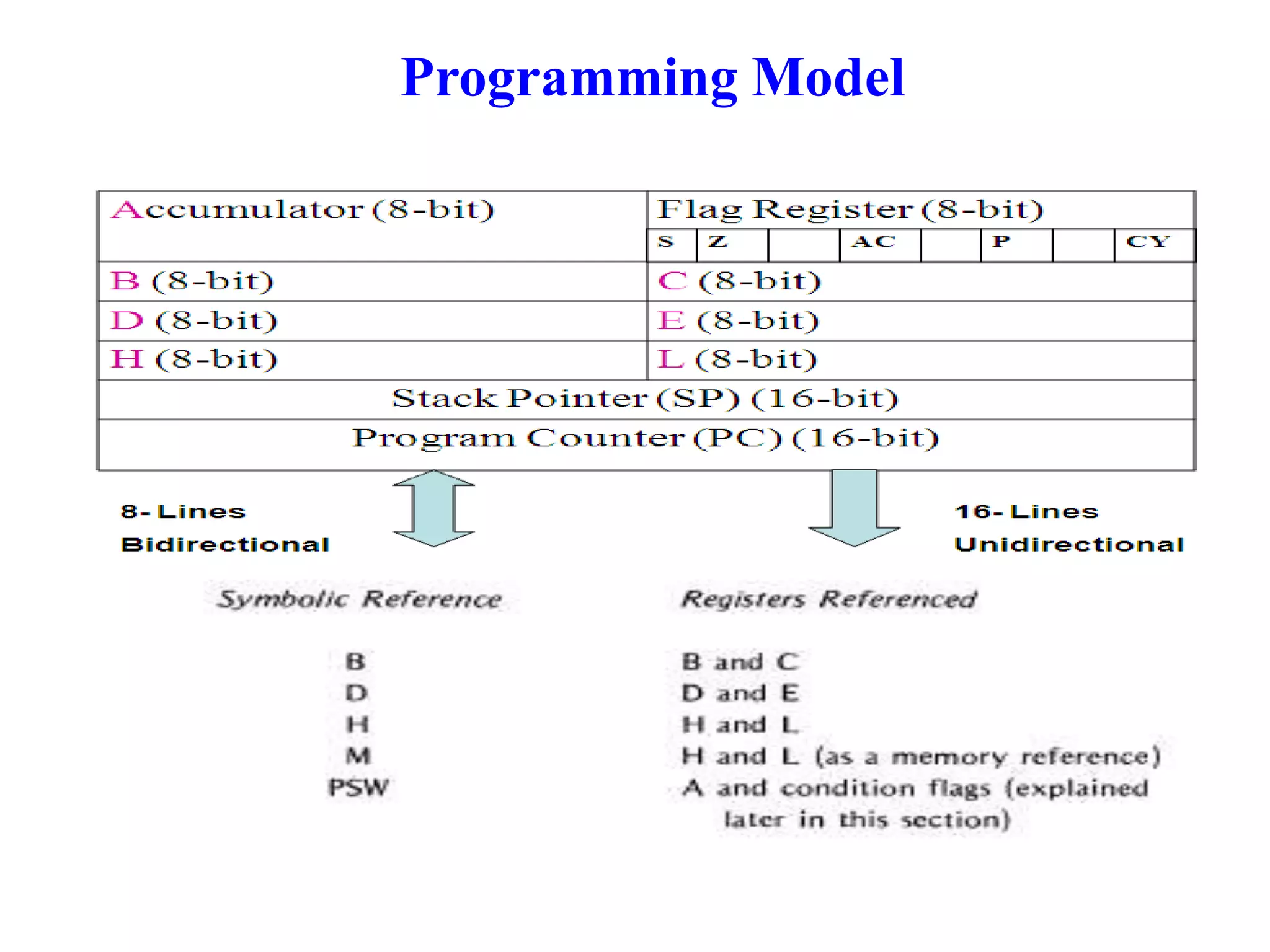
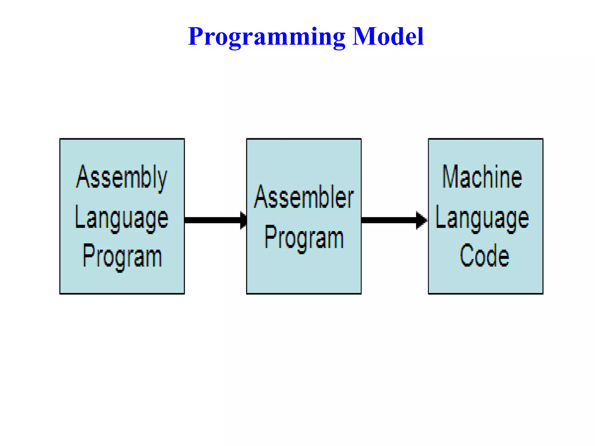
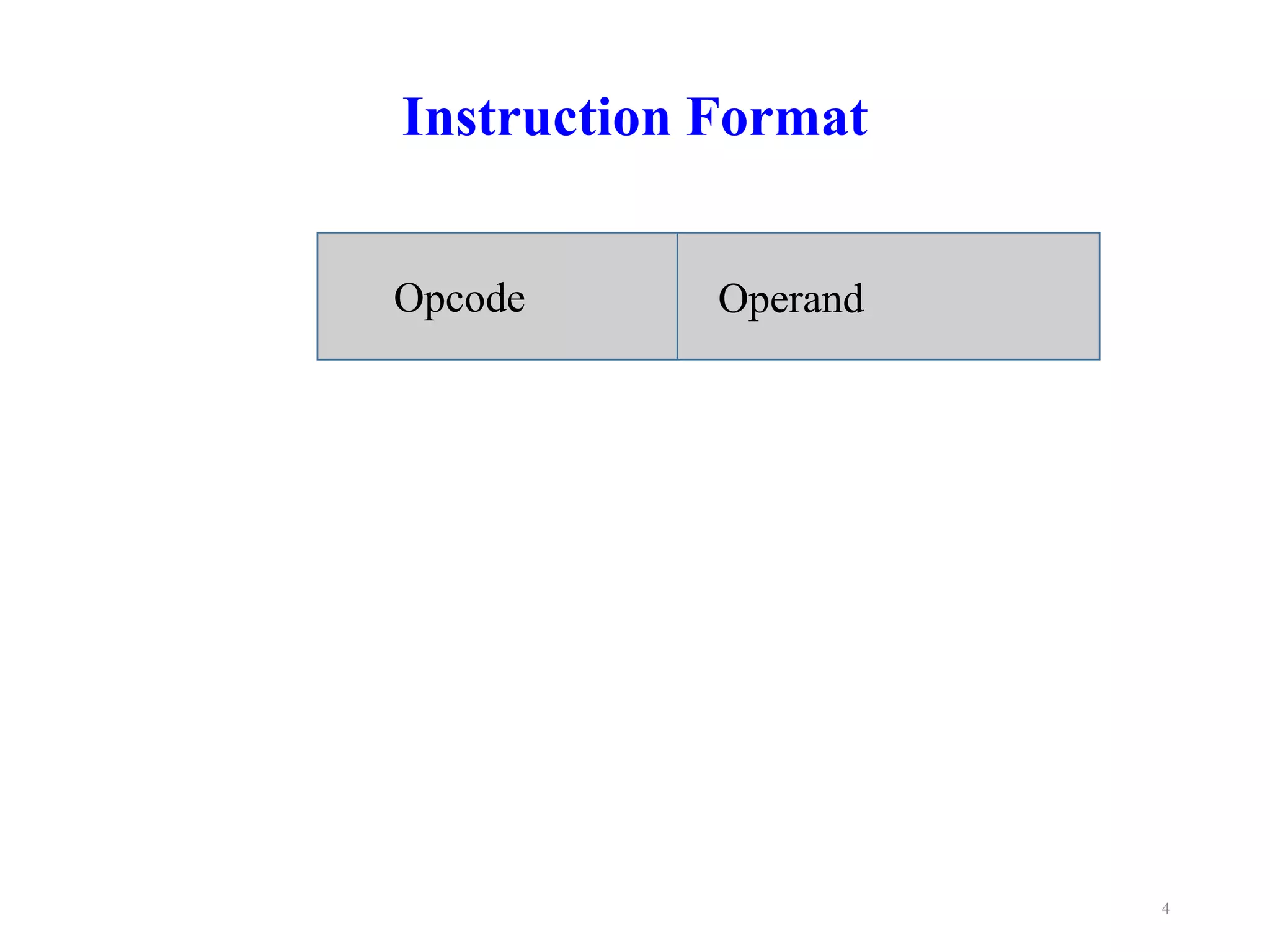
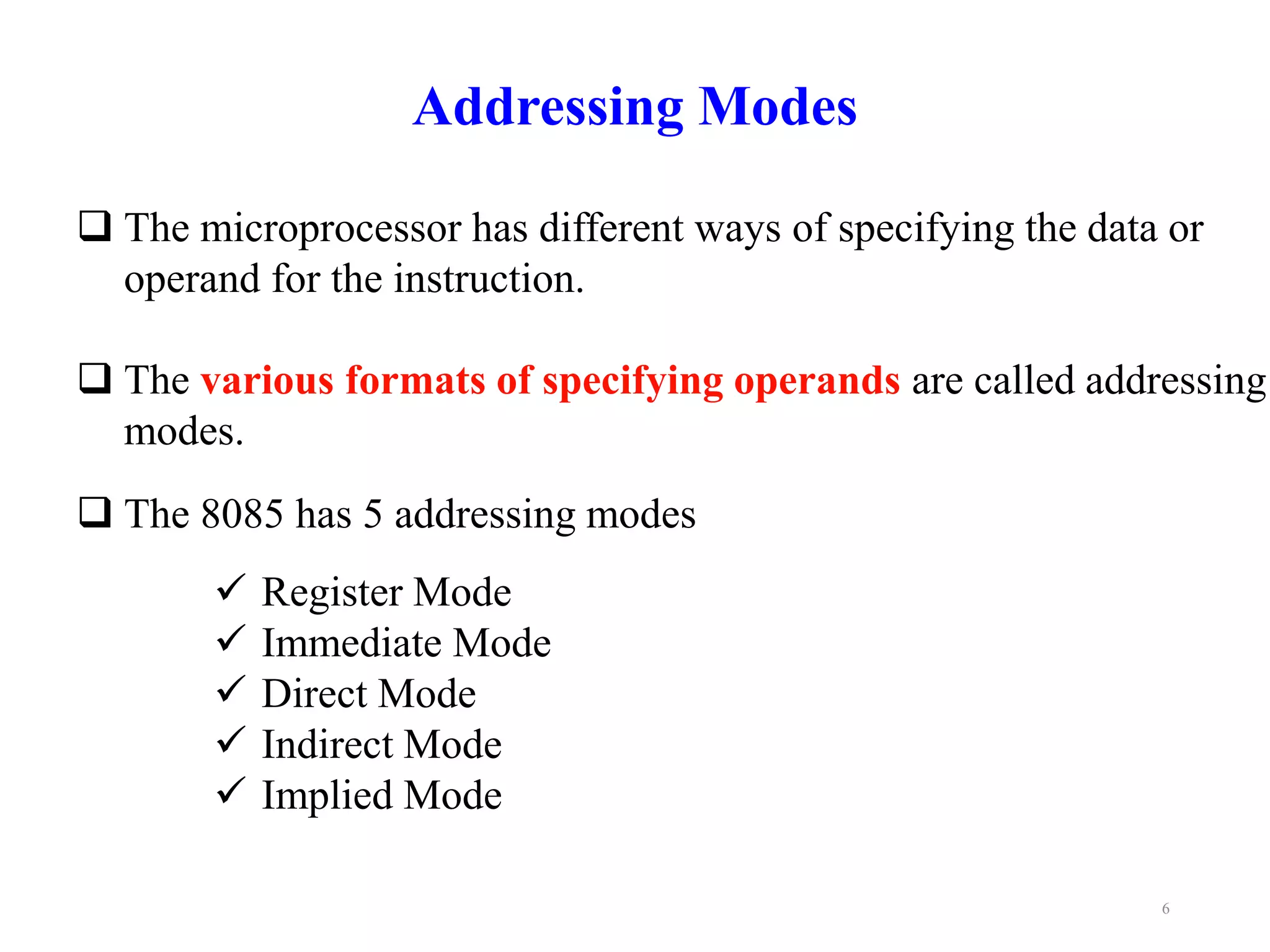
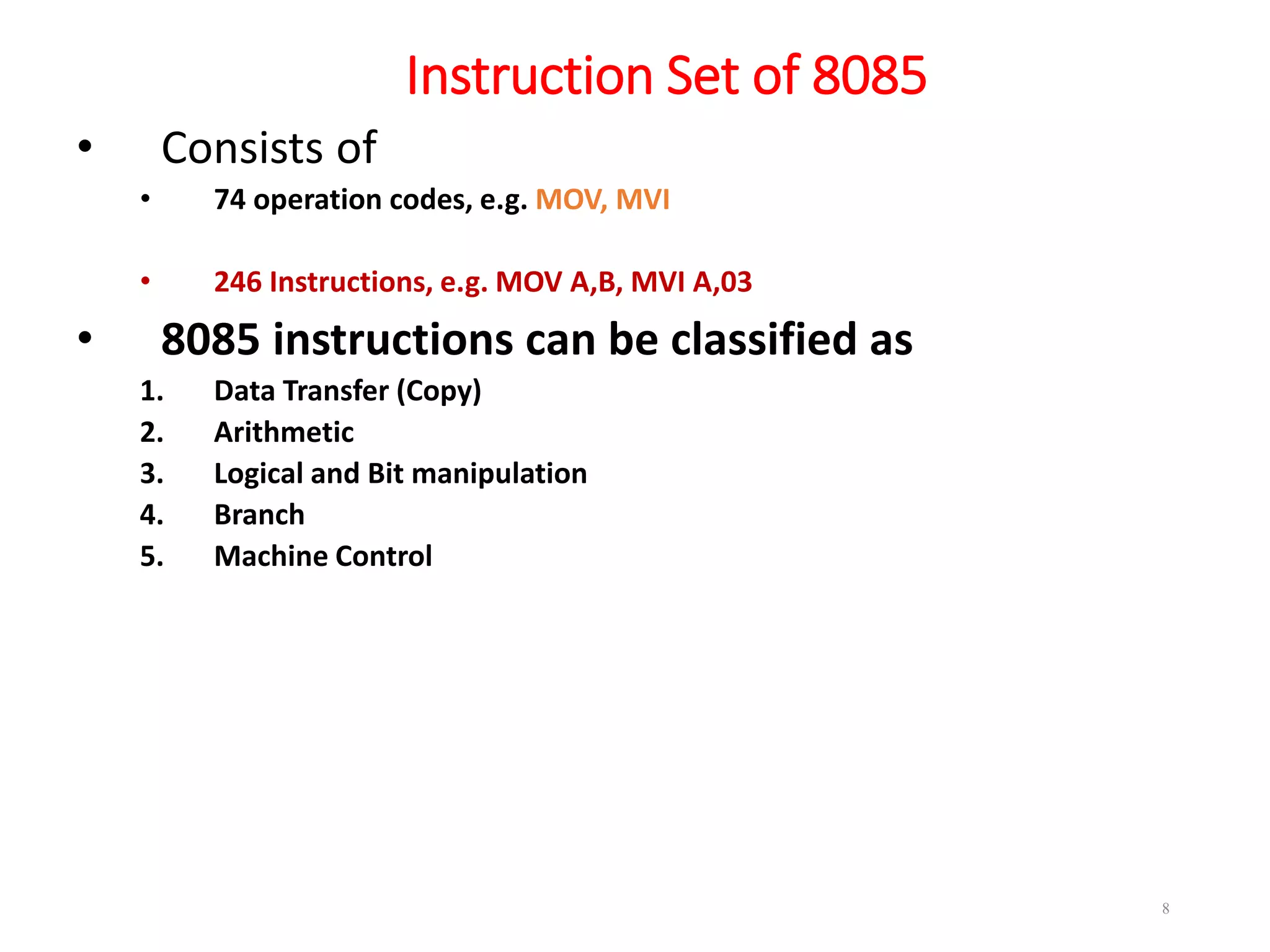
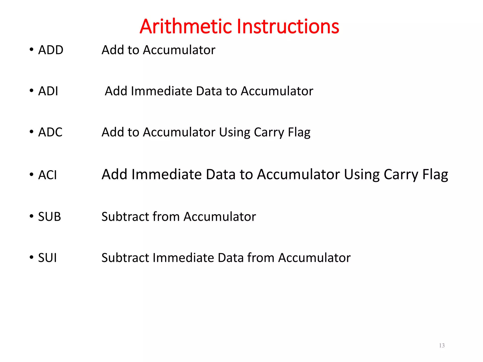
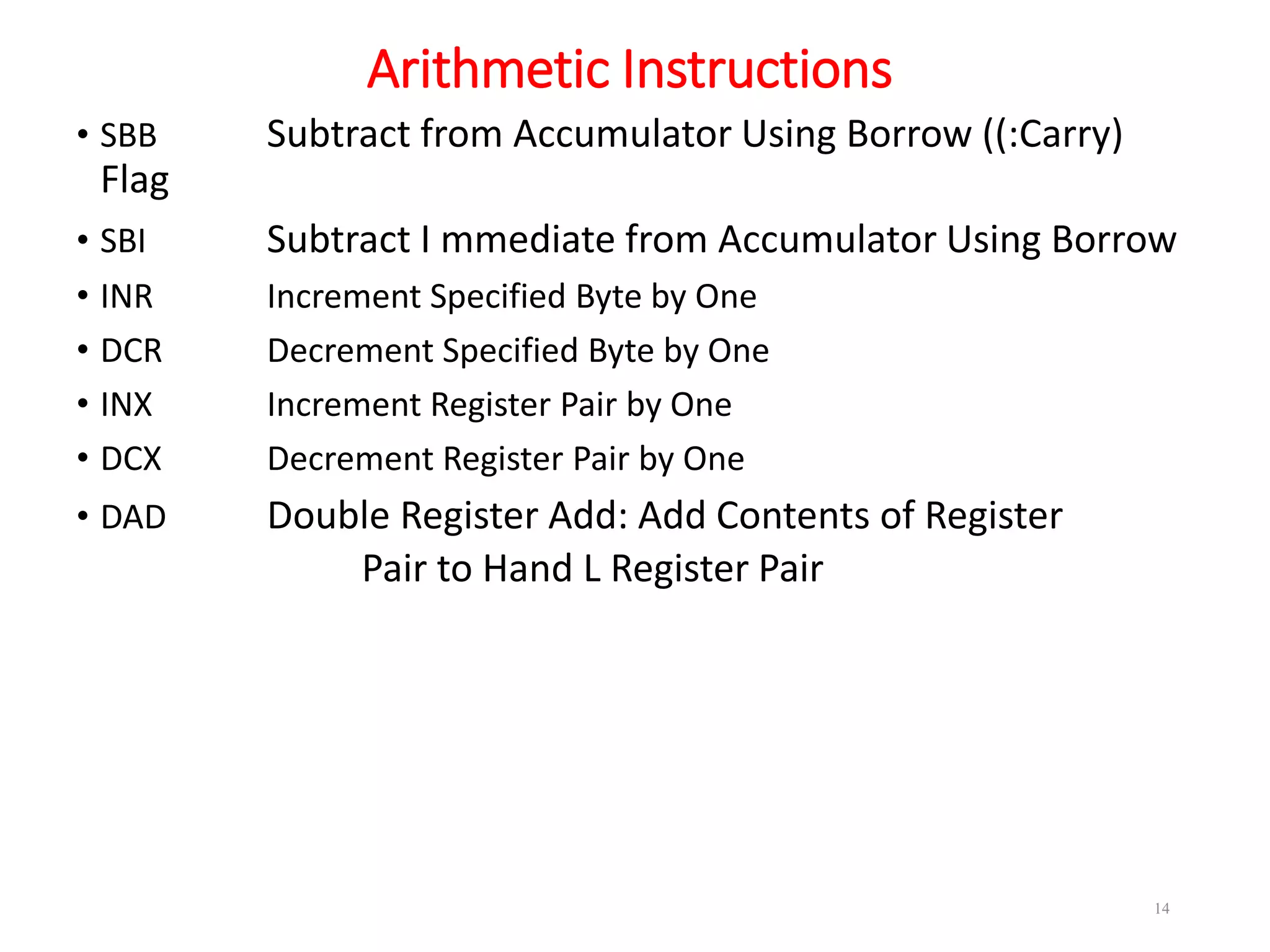
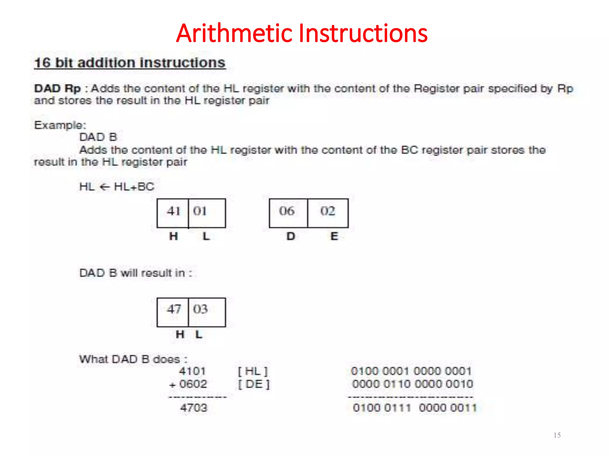
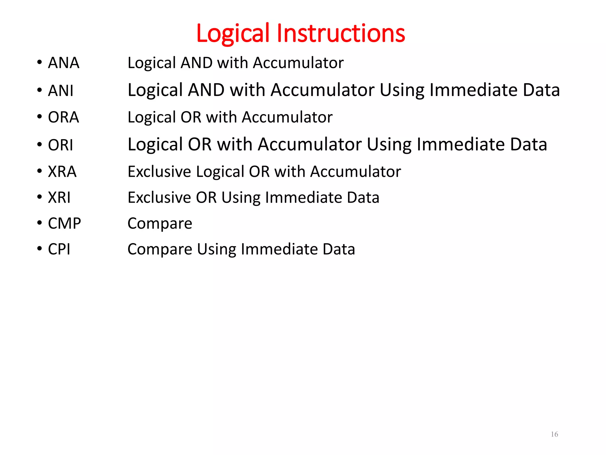
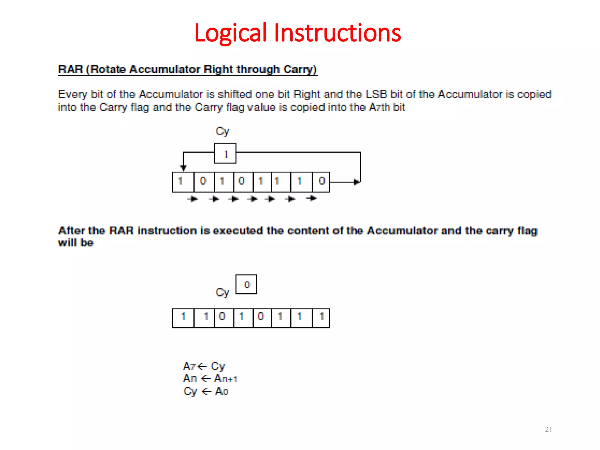
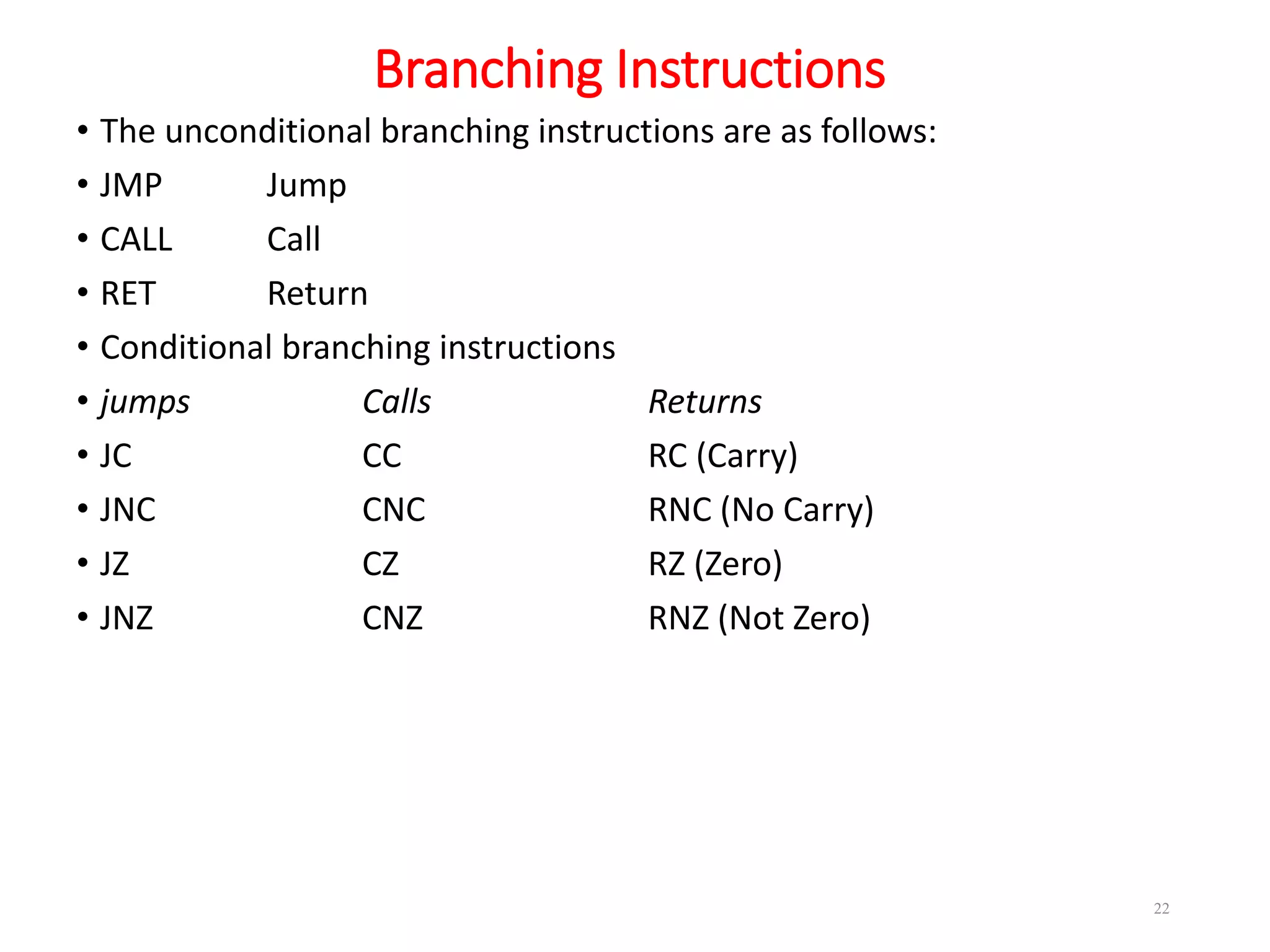
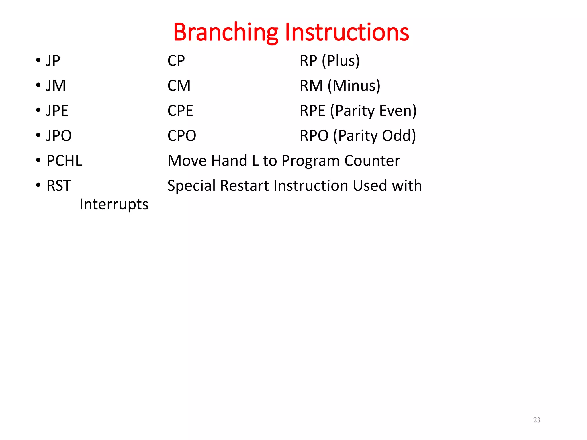
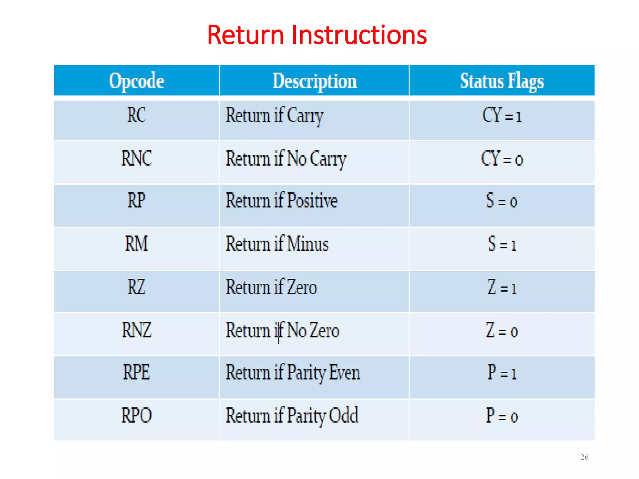
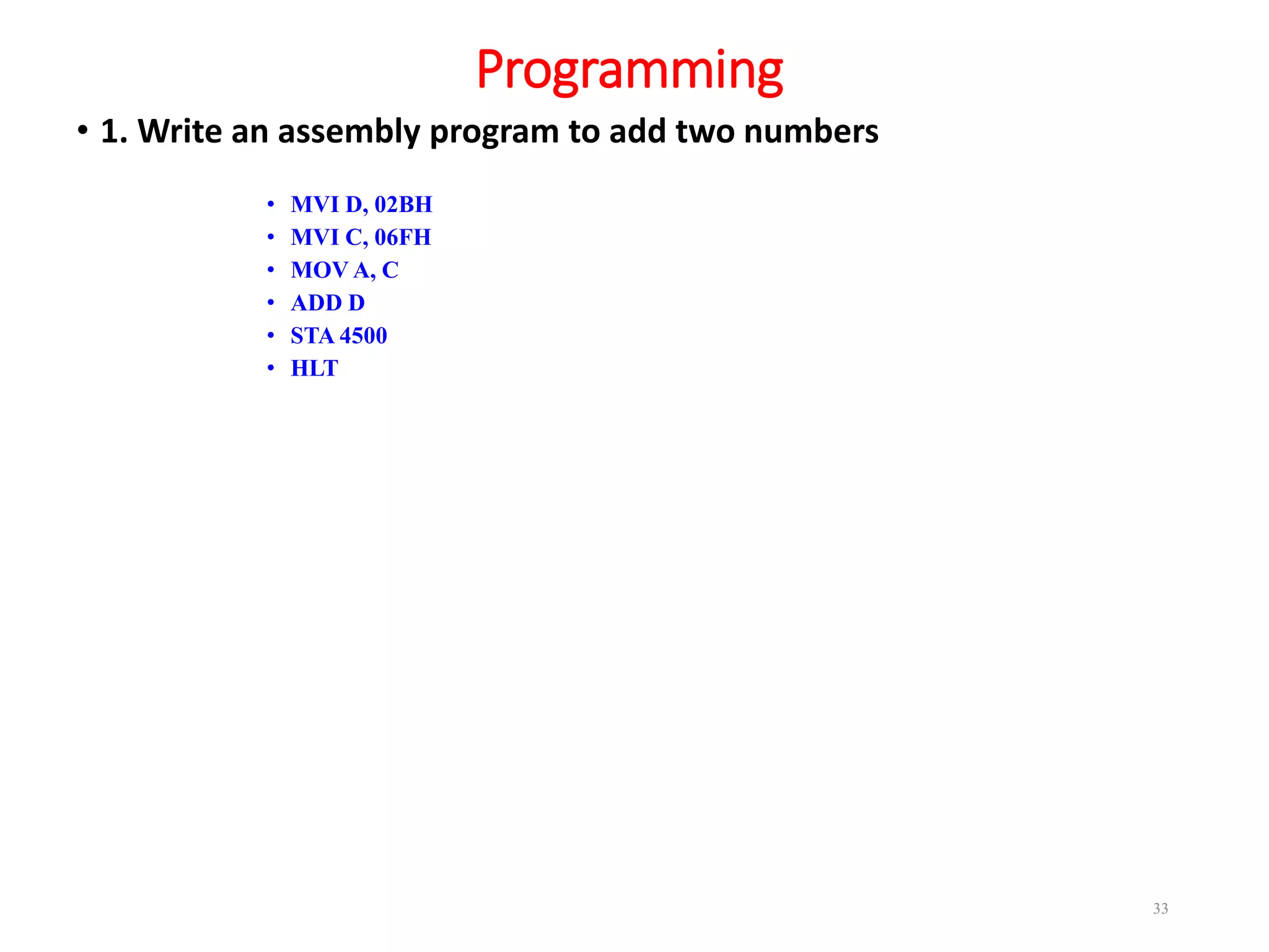
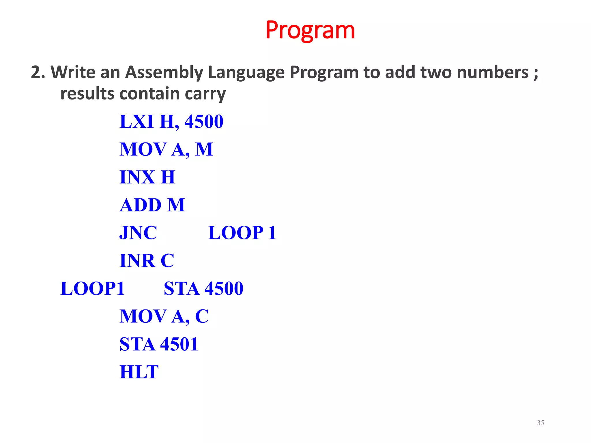
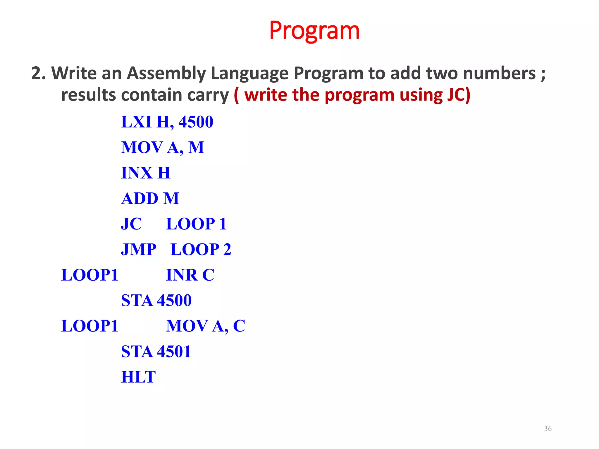
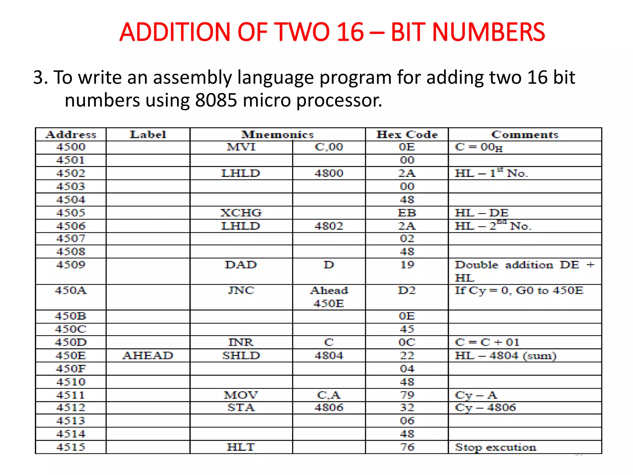
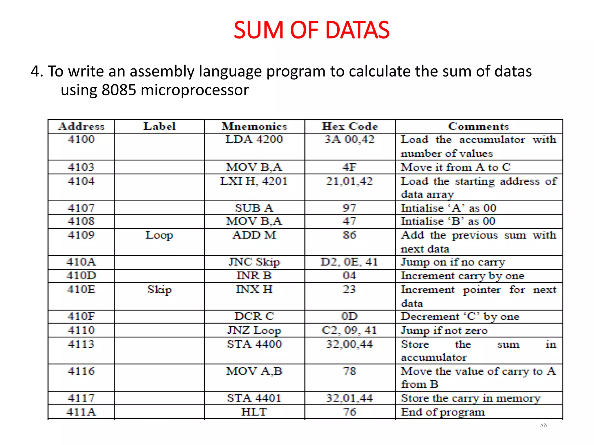
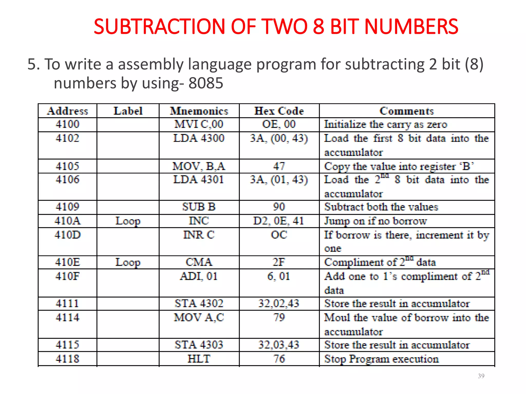
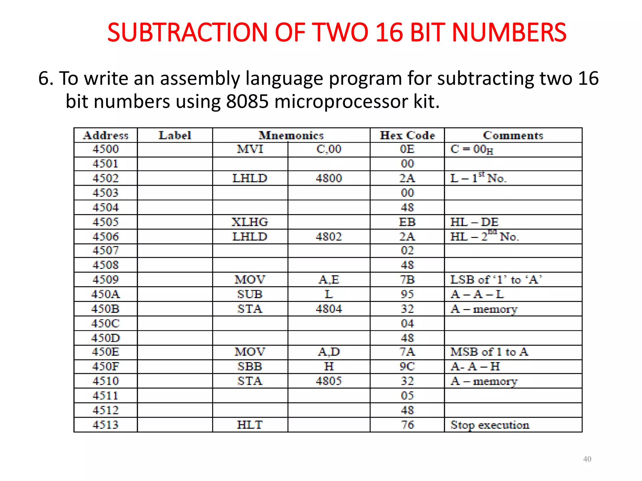
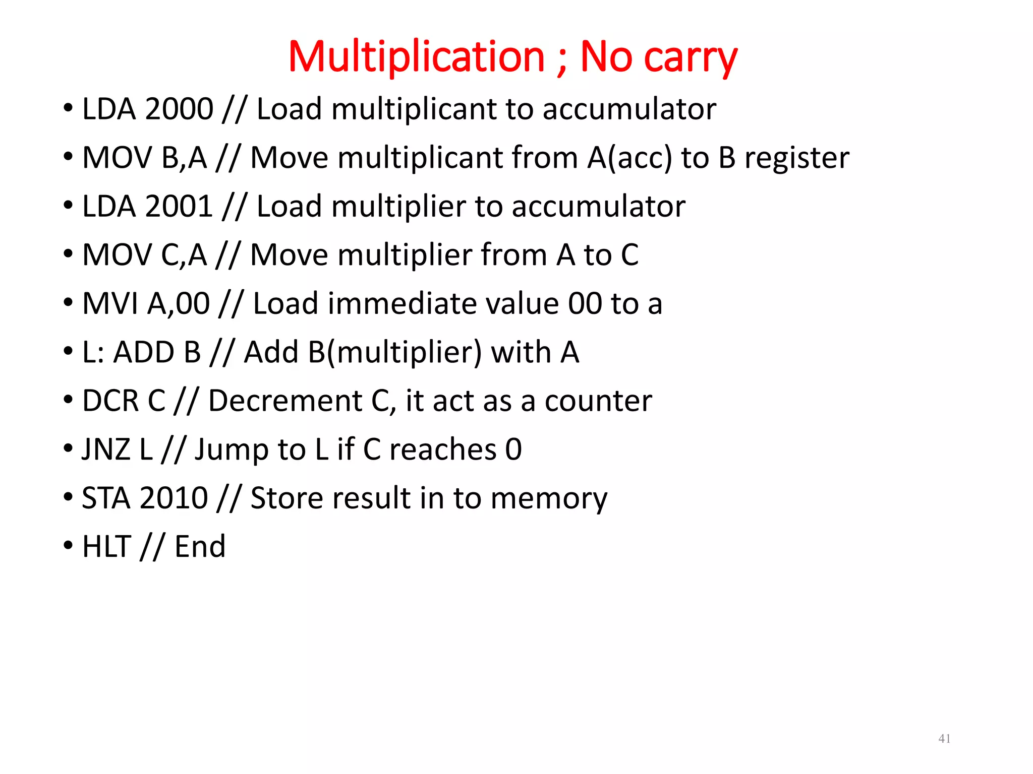
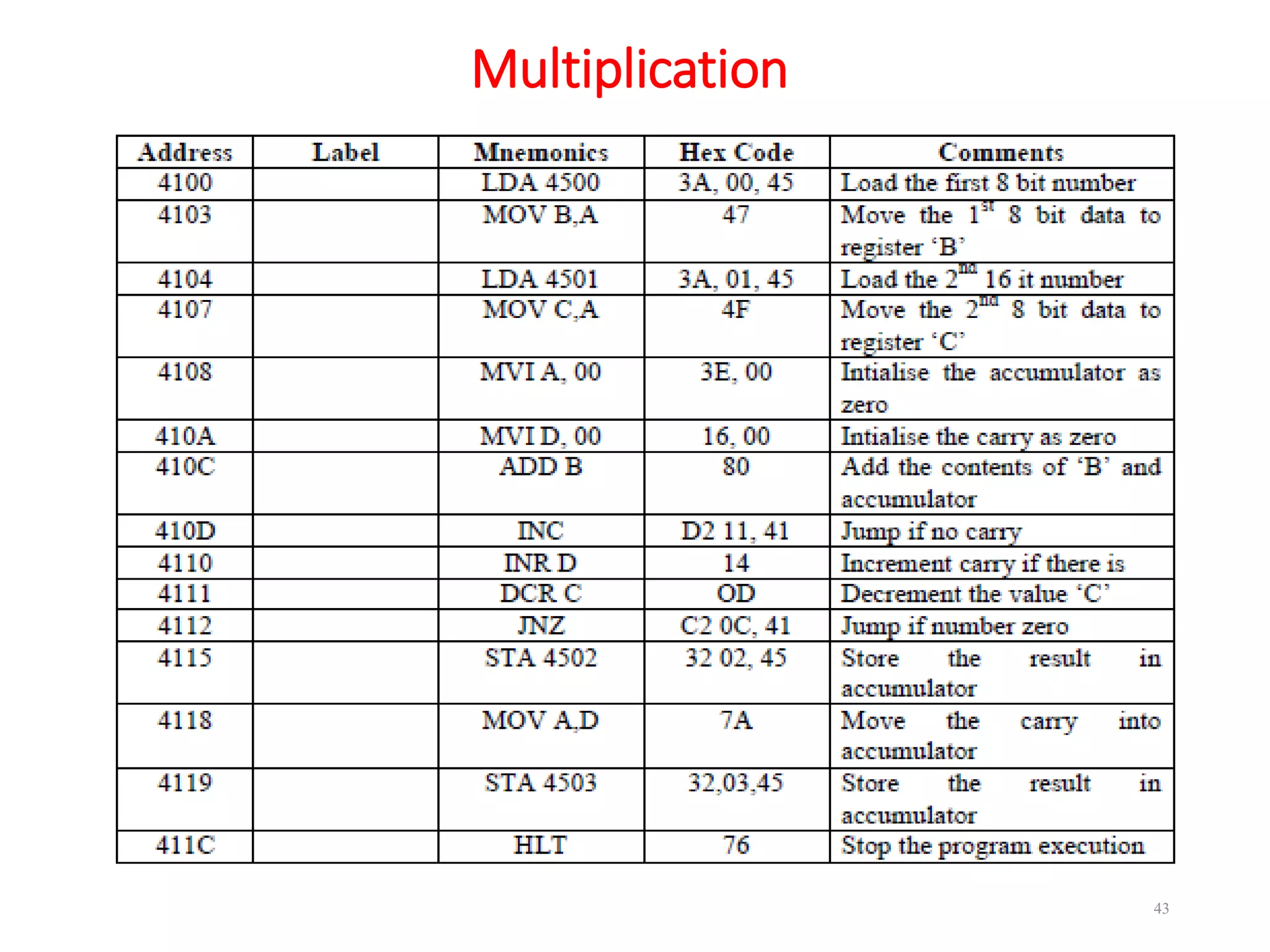
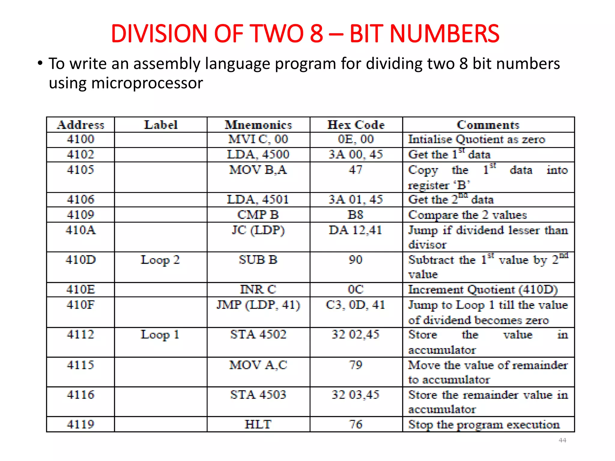
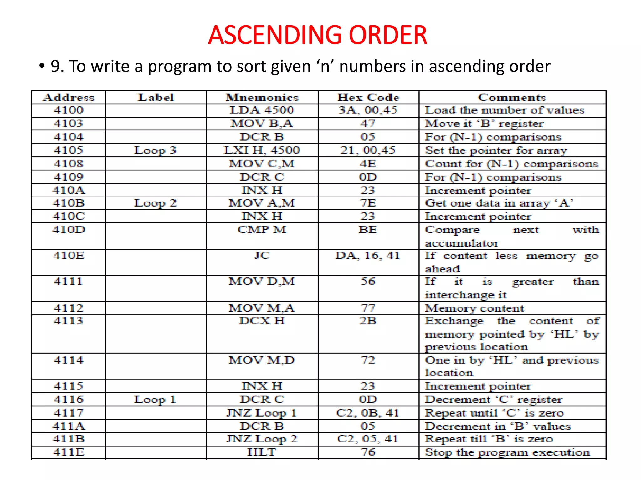
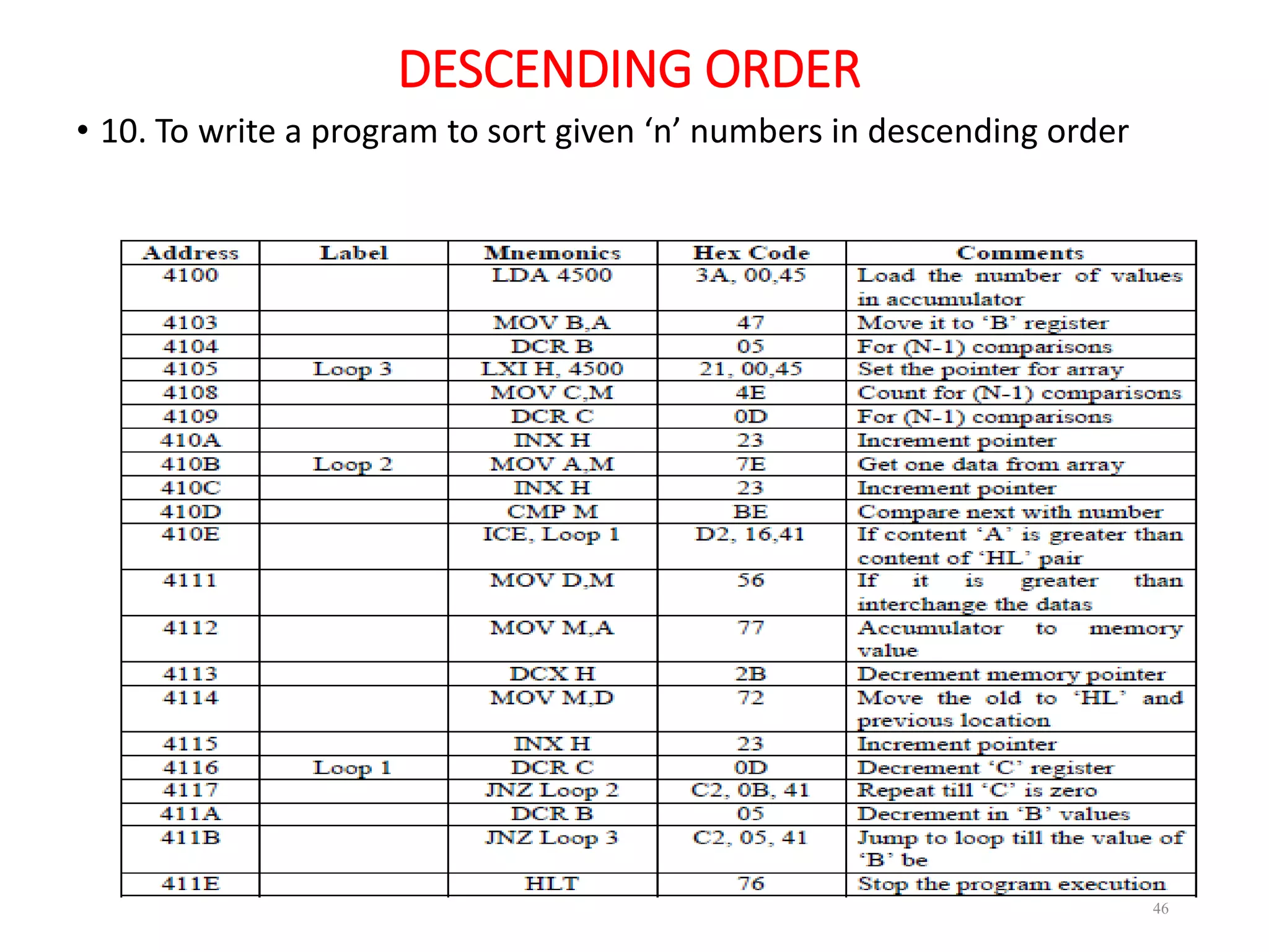
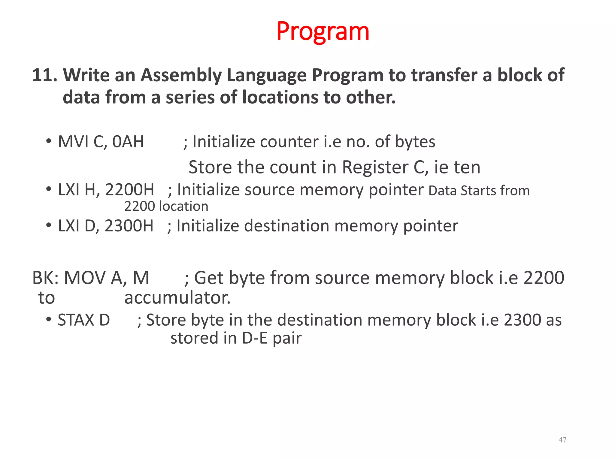
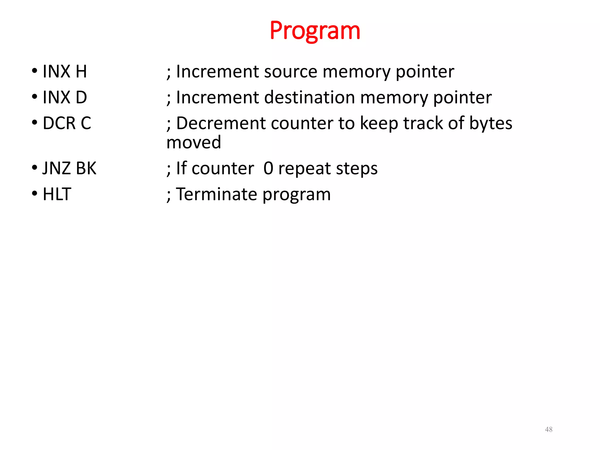
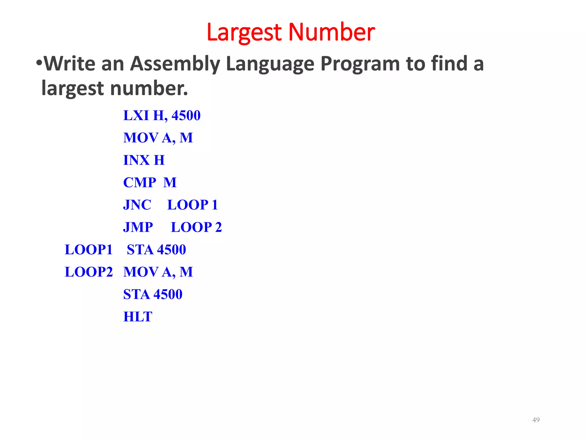
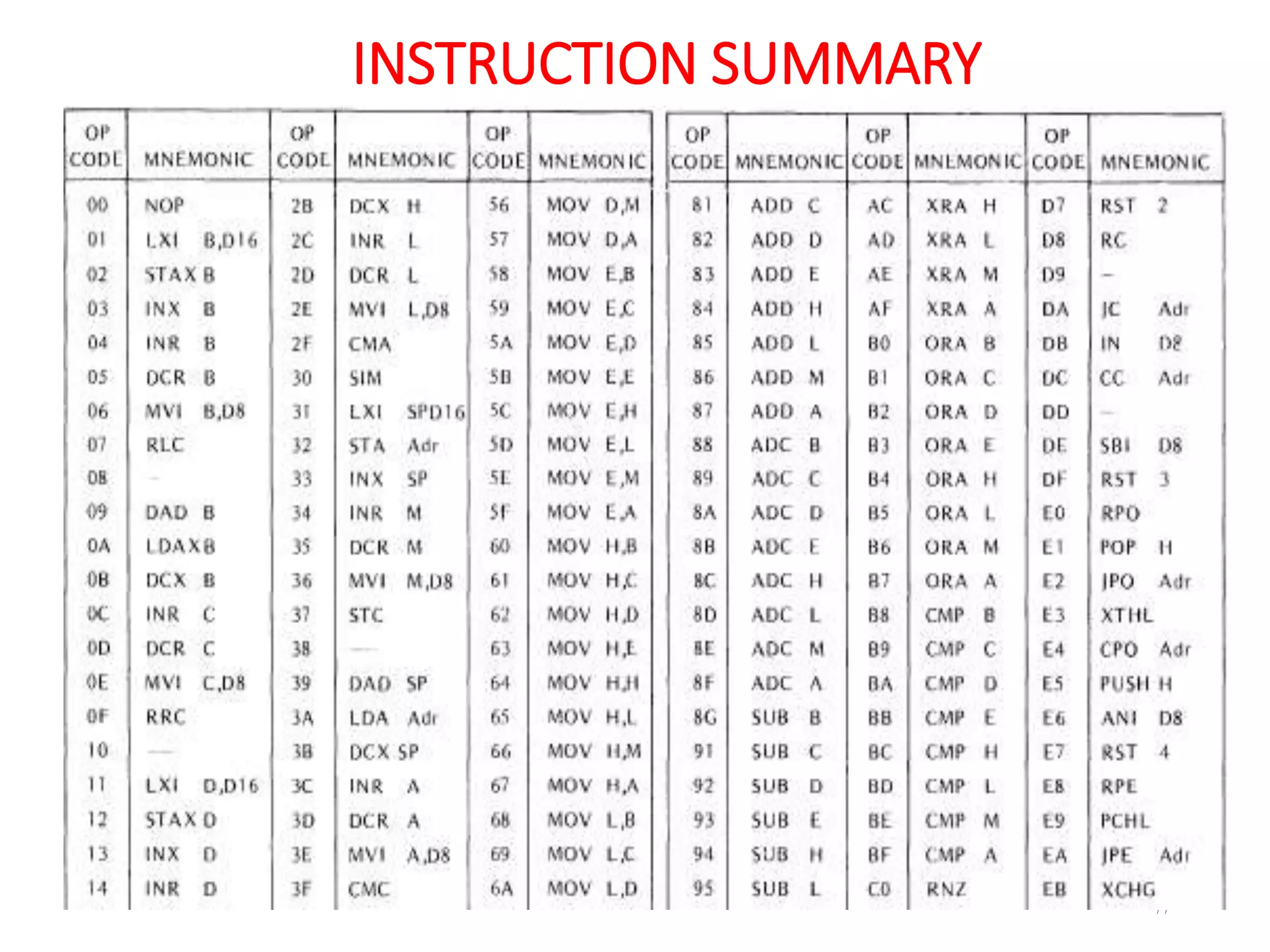
3 August 2020 1
8085
Programming Model
Er. Pooja Saini
(spst.08@gmail.Com)
Ambala College of Engineering and Applied Research, Ambala
Programming Model
3 August 2020 2
Programming Model
3 August 2020 3
3 August 2020 4
Opcode Operand
Instruction Format
3 August 2020 5
ADDRESSING MODES
3 August 2020 6
Addressing Modes
 The microprocessor has different ways of specifying the data or
operand for the instruction.
 The various formats of specifying operands are called addressing
modes.
 The 8085 has 5 addressing modes
 Register Mode
 Immediate Mode
 Direct Mode
 Indirect Mode
 Implied Mode
3 August 2020 7
INSTRUCTION SET
Instruction Set of 8085
• Consists of
• 74 operation codes, e.g. MOV, MVI
• 246 Instructions, e.g. MOV A,B, MVI A,03
• 8085 instructions can be classified as
1. Data Transfer (Copy)
2. Arithmetic
3. Logical and Bit manipulation
4. Branch
5. Machine Control
3 August 2020 8
Data Transfer Instruction
• MOV Move
• MVI Move Immediate
• LDA Load Accumulator Directly from Memory
• STA Store Accumulator Directly in Memory
• LHLD Load Hand L Registers Directly from Memory
• SHLD Store Hand L Registers Directly in Memory
• LXI Load register pair Immediate
• LDAX Load accumulator indirect
• STAX Store Accumulator In direct
• XCHG Exchange DE pair and HL pair
• XTHL Exchange between HL pair and stack
3 August 2020 9
Data Transfer Instruction
3 August 2020 10
Data Transfer Instructions
• IN portaddr
• i.e. IN 00 ( Reads data from the Input Switch, 0 0represents the port
address of the input switch)
• OUT portaddr
• i.e. OUT 00 ( Writes data to the Display device where 00 represents the
Port address of the display)
3 August 2020 11
Data Transfer Instructions
• The 256 input/output ports provide communication with the outside
world of peripheral devices.
• The IN and OUT instructions initiate data transfers.
• The I N instruction latches the number of the desired port onto the
address bus. As soon as a byte of data is returned to the data bus latch,
it is transferred into the accumulator.
• The OUT instruction latches the number of the desired port onto the
address bus and latches the data in the accumulator onto the data bus.
3 August 2020 12
Arithmetic Instructions
• ADD Add to Accumulator
• ADI Add Immediate Data to Accumulator
• ADC Add to Accumulator Using Carry Flag
• ACI Add Immediate Data to Accumulator Using Carry Flag
• SUB Subtract from Accumulator
• SUI Subtract Immediate Data from Accumulator
3 August 2020 13
Arithmetic Instructions
• SBB Subtract from Accumulator Using Borrow ((:Carry)
Flag
• SBI Subtract I mmediate from Accumulator Using Borrow
• INR Increment Specified Byte by One
• DCR Decrement Specified Byte by One
• INX Increment Register Pair by One
• DCX Decrement Register Pair by One
• DAD Double Register Add: Add Contents of Register
Pair to Hand L Register Pair
3 August 2020 14
Arithmetic Instructions
3 August 2020 15
Logical Instructions
• ANA Logical AND with Accumulator
• ANI Logical AND with Accumulator Using Immediate Data
• ORA Logical OR with Accumulator
• ORI Logical OR with Accumulator Using Immediate Data
• XRA Exclusive Logical OR with Accumulator
• XRI Exclusive OR Using Immediate Data
• CMP Compare
• CPI Compare Using Immediate Data
3 August 2020 16
Logical Instructions
• RLC Rotate Accumulator Left
• RRC Rotate Accumulator Right
• RAL Rotate Left Through Carry
• RAR Rotate Right Through Carry
• CMA Complement Accumulator
• CMC Complement Carry Flag
• STC Set Carry Flag
3 August 2020 17
Logical Instructions
3 August 2020 18
Logical Instructions
3 August 2020 19
Logical Instructions
3 August 2020 20
Logical Instructions
3 August 2020 21
Branching Instructions
• The unconditional branching instructions are as follows:
• JMP Jump
• CALL Call
• RET Return
• Conditional branching instructions
• jumps Calls Returns
• JC CC RC (Carry)
• JNC CNC RNC (No Carry)
• JZ CZ RZ (Zero)
• JNZ CNZ RNZ (Not Zero)
3 August 2020 22
Branching Instructions
• JP CP RP (Plus)
• JM CM RM (Minus)
• JPE CPE RPE (Parity Even)
• JPO CPO RPO (Parity Odd)
• PCHL Move Hand L to Program Counter
• RST Special Restart Instruction Used with
Interrupts
3 August 2020 23
Jump Instructions
3 August 2020 24
Call Instructions
3 August 2020 25
Return Instructions
3 August 2020 26
Re start Instructions
3 August 2020 27
Stack, I/O, and Machine Control Instructions.
• PUSH Push Two Bytes of Data onto the Stack
• POP Pop Two Bytes of Data off the Stack
• XTHL Exchange Top of Stack with Hand L
• SPHL Move contents of Hand L to Stack Pointer
• The I/O instructions are as follows:
• IN Initiate Input Operation
• OUT Initiate Output Operation
3 August 2020 28
Stack, I/O, and Machine Control Instructions.
• The machine control instructions are as follows:
• EI Enable Interrupt System
• DI Disable Interrupt System
• HLT Halt
• NOP No Operation
3 August 2020 29
Stack, I/O, and Machine Control Instructions.
• RIM
3 August 2020 30
Stack, I/O, and Machine Control Instructions.
• SIM
3 August 2020 31
3 August 2020 32
ASSEMBLY LANGUAGE
PROGRAMMING
Programming
• 1. Write an assembly program to add two numbers
• MVI D, 02BH
• MVI C, 06FH
• MOV A, C
• ADD D
• STA 4500
• HLT
3 August 2020 33
Program
1. Write an assembly program to add two numbers
• LXI H, 4500
• MOV A, M
• INX H
• ADD M
• STA 4500
• HLT
3 August 2020 34
Program
2. Write an Assembly Language Program to add two numbers ;
results contain carry
LXI H, 4500
MOV A, M
INX H
ADD M
JNC LOOP 1
INR C
LOOP1 STA 4500
MOV A, C
STA 4501
HLT
3 August 2020 35
Program
2. Write an Assembly Language Program to add two numbers ;
results contain carry ( write the program using JC)
LXI H, 4500
MOV A, M
INX H
ADD M
JC LOOP 1
JMP LOOP 2
LOOP1 INR C
STA 4500
LOOP1 MOV A, C
STA 4501
HLT
3 August 2020 36
ADDITION OF TWO 16 – BIT NUMBERS
3. To write an assembly language program for adding two 16 bit
numbers using 8085 micro processor.
3 August 2020 37
SUM OF DATAS
4. To write an assembly language program to calculate the sum of datas
using 8085 microprocessor
3 August 2020 38
SUBTRACTION OF TWO 8 BIT NUMBERS
5. To write a assembly language program for subtracting 2 bit (8)
numbers by using- 8085
3 August 2020 39
SUBTRACTION OF TWO 16 BIT NUMBERS
6. To write an assembly language program for subtracting two 16
bit numbers using 8085 microprocessor kit.
3 August 2020 40
Multiplication ; No carry
• LDA 2000 // Load multiplicant to accumulator
• MOV B,A // Move multiplicant from A(acc) to B register
• LDA 2001 // Load multiplier to accumulator
• MOV C,A // Move multiplier from A to C
• MVI A,00 // Load immediate value 00 to a
• L: ADD B // Add B(multiplier) with A
• DCR C // Decrement C, it act as a counter
• JNZ L // Jump to L if C reaches 0
• STA 2010 // Store result in to memory
• HLT // End
3 August 2020 41
Multiplication ; With carry
•7. Write an assembly program to multiply a number by 8
MVI C,OO
LXI H, 4100
MOV B, M
INX H
MOV A, M
DCR B
LOOP 2 ADD M
JNC LOOP1
INR C
LOOP 1 DCR B
JNZ LOOP2
STA 4500
HLT
3 August 2020 42
Multiplication
3 August 2020 43
DIVISION OF TWO 8 – BIT NUMBERS
• To write an assembly language program for dividing two 8 bit numbers
using microprocessor
3 August 2020 44
ASCENDING ORDER
• 9. To write a program to sort given ‘n’ numbers in ascending order
3 August 2020 45
DESCENDING ORDER
• 10. To write a program to sort given ‘n’ numbers in descending order
3 August 2020 46
Program
11. Write an Assembly Language Program to transfer a block of
data from a series of locations to other.
• MVI C, 0AH ; Initialize counter i.e no. of bytes
Store the count in Register C, ie ten
• LXI H, 2200H ; Initialize source memory pointer Data Starts from
2200 location
• LXI D, 2300H ; Initialize destination memory pointer
BK: MOV A, M ; Get byte from source memory block i.e 2200
to accumulator.
• STAX D ; Store byte in the destination memory block i.e 2300 as
stored in D-E pair
3 August 2020 47
Program
• INX H ; Increment source memory pointer
• INX D ; Increment destination memory pointer
• DCR C ; Decrement counter to keep track of bytes
moved
• JNZ BK ; If counter 0 repeat steps
• HLT ; Terminate program
3 August 2020 48
Largest Number
•Write an Assembly Language Program to find a
largest number.
LXI H, 4500
MOV A, M
INX H
CMP M
JNC LOOP 1
JMP LOOP 2
LOOP1 STA 4500
LOOP2 MOV A, M
STA 4500
HLT
3 August 2020 49
Smallest Number
•Write an Assembly Language Program to find a
smallest number.
LXI H, 4500
MOV A, M
INX H
CMP M
JC LOOP 1
JMP LOOP 2
LOOP1 STA 4500
LOOP2 MOV A, M
STA 4500
HLT
3 August 2020 50
Occurrence Counting
•Write an Assembly Language Program to count the
repetition of a number.
3 August 2020 51
UP Counting
•Write an Assembly Language Program to count up to
7F
3 August 2020 52
UP Counting
•Write an Assembly Language Program to count from
&F to 00 , downwards
3 August 2020 53
3 August 2020 54
STACK AND SUBROUTINE
STACK
• The stack is an area of memory identified by the programmer for
temporary storage of information.
• The stack is a LIFO structure.
• The stack normally grows backwards into memory.
• Programmer can defines the bottom of (SP) the stack and the stack
grows up into reducing address range.
3 August 2020 55
STACK
• Stack is defined by setting the SP (Stack Pointer) register.
• LXI SP, FFFFH ,This sets SP to location FFFFH (end of memory for 8085).
3 August 2020 56
STACK
• Save information by PUSHing onto STACK
• Retrieved from STACK by POPing it off.
• PUSH and POP work with register pairs only.
• Example “PUSH B”
• – Decrement SP, Copy B to (SP-1)
• – Decrement SP, Copy C to (SP-1)
• Example “POP B”
• – Copy (SP+1) to C, Increment SP
• – Copy (SP+1) to B, Increment SP
3 August 2020 57
SUBROUTINE
• A subroutine is a group of instructions that is used repeatedly in
different places of the program.
• It can be grouped into a subroutine and call from the different
locations.
• The CALL instruction is used to redirect program execution to the
subroutine.
• The RET instruction is used to return the execution to the calling
routine.
3 August 2020 58
SUBROUTINE
• You must set the SP correctly before using CALL
• CALL 5000H
• – Push the PC value onto the stack
• – Load PC with 16‐bit address supplied CALL ins.
• RET : Load PC with stack top; POP PC
3 August 2020 59
SUBROUTINE
3 August 2020 60
SUBROUTINE
• SUBRTN:
• PUSH PSW
• PUSH B
• PUSH D
• PUSH H
•subroutine coding
• POP H
• POP D
• POP B
• POP PSW
• RETURN
3 August 2020 61
3 August 2020 62
SERIAL INPUT / OUTPUT
OPERATION
Serial Input /Out put
• 8085 Microprocessor has two Serial Input/output pins that are
used to read/write one bit data to and from peripheral
devices.
• SID (Serial Input Data line)
• There is an One bit Input line inside the 8085 CPU (SID line ,Pin
number 5)
• -The data that is read is stored in the A7th bit of the
Accumulator
• -RIM instruction is used to read the SID line
3 August 2020 63
Serial Input
3 August 2020 64
Serial Input
• Example Pseudocode:
• 1) RIM
• 2) A7 (SID)
• As seen from the figure 1, if the SID line is connected with +5V
and RIM instruction is executed, then the Accumulator’s MSB
bit will be loaded with a Logic 1
3 August 2020 65
Serial Input
3 August 2020 66
Serial Input
• RIM
3 August 2020 67
SOD (Serial Output Data) Line
• -There is a One bit Output port inside the 8085 CPU (Pin
number 4
• -1 bit data can be externally written in this port.
• -To write data into this port, SIM instruction is used.
• -The data that is to be written in this port must be stored in the
A7th bit of the Accumulator.
• Bit A6 of the Accumulator is known as SOE (Serial output
Enable).
• This bit Must be set to 1 to enable Serial data output.
3 August 2020 68
SOD (Serial Output Data) Line
3 August 2020 69
SOD (Serial Output Data) Line
3 August 2020 70
SOD (Serial Output Data) Line
•Pseudocode:
•A 40H
•SIM
•SOD (A7)
3 August 2020 71
SOD (Serial Output Data) Line
• S
3 August 2020 72
SIM
Problem
• The SID Pin of an 8085 microprocessor is connected with a
0V/+5V source and the SOD Pin is connected with a LED. Write
down the Pseudocode that will read the SID pin of the
microprocessor and glow the LED if the SID pin is connected
with a +5V source otherwise Turn the Led off if the SID Pin is
connected with GND (0V)
3 August 2020 73
INSTRUCTION SUMMARY
3 August 2020 74
INSTRUCTION SUMMARY
3 August 2020 75
INSTRUCTION SUMMARY
3 August 2020 76
INSTRUCTION SUMMARY
3 August 2020 77
INSTRUCTION SUMMARY
3 August 2020 78

8085 instruction set and Programming

  • 1.
    3 August 20201 8085 Programming Model Er. Pooja Saini (spst.08@gmail.Com) Ambala College of Engineering and Applied Research, Ambala
  • 2.
  • 3.
  • 4.
    3 August 20204 Opcode Operand Instruction Format
  • 5.
    3 August 20205 ADDRESSING MODES
  • 6.
    3 August 20206 Addressing Modes  The microprocessor has different ways of specifying the data or operand for the instruction.  The various formats of specifying operands are called addressing modes.  The 8085 has 5 addressing modes  Register Mode  Immediate Mode  Direct Mode  Indirect Mode  Implied Mode
  • 7.
    3 August 20207 INSTRUCTION SET
  • 8.
    Instruction Set of8085 • Consists of • 74 operation codes, e.g. MOV, MVI • 246 Instructions, e.g. MOV A,B, MVI A,03 • 8085 instructions can be classified as 1. Data Transfer (Copy) 2. Arithmetic 3. Logical and Bit manipulation 4. Branch 5. Machine Control 3 August 2020 8
  • 9.
    Data Transfer Instruction •MOV Move • MVI Move Immediate • LDA Load Accumulator Directly from Memory • STA Store Accumulator Directly in Memory • LHLD Load Hand L Registers Directly from Memory • SHLD Store Hand L Registers Directly in Memory • LXI Load register pair Immediate • LDAX Load accumulator indirect • STAX Store Accumulator In direct • XCHG Exchange DE pair and HL pair • XTHL Exchange between HL pair and stack 3 August 2020 9
  • 10.
  • 11.
    Data Transfer Instructions •IN portaddr • i.e. IN 00 ( Reads data from the Input Switch, 0 0represents the port address of the input switch) • OUT portaddr • i.e. OUT 00 ( Writes data to the Display device where 00 represents the Port address of the display) 3 August 2020 11
  • 12.
    Data Transfer Instructions •The 256 input/output ports provide communication with the outside world of peripheral devices. • The IN and OUT instructions initiate data transfers. • The I N instruction latches the number of the desired port onto the address bus. As soon as a byte of data is returned to the data bus latch, it is transferred into the accumulator. • The OUT instruction latches the number of the desired port onto the address bus and latches the data in the accumulator onto the data bus. 3 August 2020 12
  • 13.
    Arithmetic Instructions • ADDAdd to Accumulator • ADI Add Immediate Data to Accumulator • ADC Add to Accumulator Using Carry Flag • ACI Add Immediate Data to Accumulator Using Carry Flag • SUB Subtract from Accumulator • SUI Subtract Immediate Data from Accumulator 3 August 2020 13
  • 14.
    Arithmetic Instructions • SBBSubtract from Accumulator Using Borrow ((:Carry) Flag • SBI Subtract I mmediate from Accumulator Using Borrow • INR Increment Specified Byte by One • DCR Decrement Specified Byte by One • INX Increment Register Pair by One • DCX Decrement Register Pair by One • DAD Double Register Add: Add Contents of Register Pair to Hand L Register Pair 3 August 2020 14
  • 15.
  • 16.
    Logical Instructions • ANALogical AND with Accumulator • ANI Logical AND with Accumulator Using Immediate Data • ORA Logical OR with Accumulator • ORI Logical OR with Accumulator Using Immediate Data • XRA Exclusive Logical OR with Accumulator • XRI Exclusive OR Using Immediate Data • CMP Compare • CPI Compare Using Immediate Data 3 August 2020 16
  • 17.
    Logical Instructions • RLCRotate Accumulator Left • RRC Rotate Accumulator Right • RAL Rotate Left Through Carry • RAR Rotate Right Through Carry • CMA Complement Accumulator • CMC Complement Carry Flag • STC Set Carry Flag 3 August 2020 17
  • 18.
  • 19.
  • 20.
  • 21.
  • 22.
    Branching Instructions • Theunconditional branching instructions are as follows: • JMP Jump • CALL Call • RET Return • Conditional branching instructions • jumps Calls Returns • JC CC RC (Carry) • JNC CNC RNC (No Carry) • JZ CZ RZ (Zero) • JNZ CNZ RNZ (Not Zero) 3 August 2020 22
  • 23.
    Branching Instructions • JPCP RP (Plus) • JM CM RM (Minus) • JPE CPE RPE (Parity Even) • JPO CPO RPO (Parity Odd) • PCHL Move Hand L to Program Counter • RST Special Restart Instruction Used with Interrupts 3 August 2020 23
  • 24.
  • 25.
  • 26.
  • 27.
  • 28.
    Stack, I/O, andMachine Control Instructions. • PUSH Push Two Bytes of Data onto the Stack • POP Pop Two Bytes of Data off the Stack • XTHL Exchange Top of Stack with Hand L • SPHL Move contents of Hand L to Stack Pointer • The I/O instructions are as follows: • IN Initiate Input Operation • OUT Initiate Output Operation 3 August 2020 28
  • 29.
    Stack, I/O, andMachine Control Instructions. • The machine control instructions are as follows: • EI Enable Interrupt System • DI Disable Interrupt System • HLT Halt • NOP No Operation 3 August 2020 29
  • 30.
    Stack, I/O, andMachine Control Instructions. • RIM 3 August 2020 30
  • 31.
    Stack, I/O, andMachine Control Instructions. • SIM 3 August 2020 31
  • 32.
    3 August 202032 ASSEMBLY LANGUAGE PROGRAMMING
  • 33.
    Programming • 1. Writean assembly program to add two numbers • MVI D, 02BH • MVI C, 06FH • MOV A, C • ADD D • STA 4500 • HLT 3 August 2020 33
  • 34.
    Program 1. Write anassembly program to add two numbers • LXI H, 4500 • MOV A, M • INX H • ADD M • STA 4500 • HLT 3 August 2020 34
  • 35.
    Program 2. Write anAssembly Language Program to add two numbers ; results contain carry LXI H, 4500 MOV A, M INX H ADD M JNC LOOP 1 INR C LOOP1 STA 4500 MOV A, C STA 4501 HLT 3 August 2020 35
  • 36.
    Program 2. Write anAssembly Language Program to add two numbers ; results contain carry ( write the program using JC) LXI H, 4500 MOV A, M INX H ADD M JC LOOP 1 JMP LOOP 2 LOOP1 INR C STA 4500 LOOP1 MOV A, C STA 4501 HLT 3 August 2020 36
  • 37.
    ADDITION OF TWO16 – BIT NUMBERS 3. To write an assembly language program for adding two 16 bit numbers using 8085 micro processor. 3 August 2020 37
  • 38.
    SUM OF DATAS 4.To write an assembly language program to calculate the sum of datas using 8085 microprocessor 3 August 2020 38
  • 39.
    SUBTRACTION OF TWO8 BIT NUMBERS 5. To write a assembly language program for subtracting 2 bit (8) numbers by using- 8085 3 August 2020 39
  • 40.
    SUBTRACTION OF TWO16 BIT NUMBERS 6. To write an assembly language program for subtracting two 16 bit numbers using 8085 microprocessor kit. 3 August 2020 40
  • 41.
    Multiplication ; Nocarry • LDA 2000 // Load multiplicant to accumulator • MOV B,A // Move multiplicant from A(acc) to B register • LDA 2001 // Load multiplier to accumulator • MOV C,A // Move multiplier from A to C • MVI A,00 // Load immediate value 00 to a • L: ADD B // Add B(multiplier) with A • DCR C // Decrement C, it act as a counter • JNZ L // Jump to L if C reaches 0 • STA 2010 // Store result in to memory • HLT // End 3 August 2020 41
  • 42.
    Multiplication ; Withcarry •7. Write an assembly program to multiply a number by 8 MVI C,OO LXI H, 4100 MOV B, M INX H MOV A, M DCR B LOOP 2 ADD M JNC LOOP1 INR C LOOP 1 DCR B JNZ LOOP2 STA 4500 HLT 3 August 2020 42
  • 43.
  • 44.
    DIVISION OF TWO8 – BIT NUMBERS • To write an assembly language program for dividing two 8 bit numbers using microprocessor 3 August 2020 44
  • 45.
    ASCENDING ORDER • 9.To write a program to sort given ‘n’ numbers in ascending order 3 August 2020 45
  • 46.
    DESCENDING ORDER • 10.To write a program to sort given ‘n’ numbers in descending order 3 August 2020 46
  • 47.
    Program 11. Write anAssembly Language Program to transfer a block of data from a series of locations to other. • MVI C, 0AH ; Initialize counter i.e no. of bytes Store the count in Register C, ie ten • LXI H, 2200H ; Initialize source memory pointer Data Starts from 2200 location • LXI D, 2300H ; Initialize destination memory pointer BK: MOV A, M ; Get byte from source memory block i.e 2200 to accumulator. • STAX D ; Store byte in the destination memory block i.e 2300 as stored in D-E pair 3 August 2020 47
  • 48.
    Program • INX H; Increment source memory pointer • INX D ; Increment destination memory pointer • DCR C ; Decrement counter to keep track of bytes moved • JNZ BK ; If counter 0 repeat steps • HLT ; Terminate program 3 August 2020 48
  • 49.
    Largest Number •Write anAssembly Language Program to find a largest number. LXI H, 4500 MOV A, M INX H CMP M JNC LOOP 1 JMP LOOP 2 LOOP1 STA 4500 LOOP2 MOV A, M STA 4500 HLT 3 August 2020 49
  • 50.
    Smallest Number •Write anAssembly Language Program to find a smallest number. LXI H, 4500 MOV A, M INX H CMP M JC LOOP 1 JMP LOOP 2 LOOP1 STA 4500 LOOP2 MOV A, M STA 4500 HLT 3 August 2020 50
  • 51.
    Occurrence Counting •Write anAssembly Language Program to count the repetition of a number. 3 August 2020 51
  • 52.
    UP Counting •Write anAssembly Language Program to count up to 7F 3 August 2020 52
  • 53.
    UP Counting •Write anAssembly Language Program to count from &F to 00 , downwards 3 August 2020 53
  • 54.
    3 August 202054 STACK AND SUBROUTINE
  • 55.
    STACK • The stackis an area of memory identified by the programmer for temporary storage of information. • The stack is a LIFO structure. • The stack normally grows backwards into memory. • Programmer can defines the bottom of (SP) the stack and the stack grows up into reducing address range. 3 August 2020 55
  • 56.
    STACK • Stack isdefined by setting the SP (Stack Pointer) register. • LXI SP, FFFFH ,This sets SP to location FFFFH (end of memory for 8085). 3 August 2020 56
  • 57.
    STACK • Save informationby PUSHing onto STACK • Retrieved from STACK by POPing it off. • PUSH and POP work with register pairs only. • Example “PUSH B” • – Decrement SP, Copy B to (SP-1) • – Decrement SP, Copy C to (SP-1) • Example “POP B” • – Copy (SP+1) to C, Increment SP • – Copy (SP+1) to B, Increment SP 3 August 2020 57
  • 58.
    SUBROUTINE • A subroutineis a group of instructions that is used repeatedly in different places of the program. • It can be grouped into a subroutine and call from the different locations. • The CALL instruction is used to redirect program execution to the subroutine. • The RET instruction is used to return the execution to the calling routine. 3 August 2020 58
  • 59.
    SUBROUTINE • You mustset the SP correctly before using CALL • CALL 5000H • – Push the PC value onto the stack • – Load PC with 16‐bit address supplied CALL ins. • RET : Load PC with stack top; POP PC 3 August 2020 59
  • 60.
  • 61.
    SUBROUTINE • SUBRTN: • PUSHPSW • PUSH B • PUSH D • PUSH H •subroutine coding • POP H • POP D • POP B • POP PSW • RETURN 3 August 2020 61
  • 62.
    3 August 202062 SERIAL INPUT / OUTPUT OPERATION
  • 63.
    Serial Input /Output • 8085 Microprocessor has two Serial Input/output pins that are used to read/write one bit data to and from peripheral devices. • SID (Serial Input Data line) • There is an One bit Input line inside the 8085 CPU (SID line ,Pin number 5) • -The data that is read is stored in the A7th bit of the Accumulator • -RIM instruction is used to read the SID line 3 August 2020 63
  • 64.
  • 65.
    Serial Input • ExamplePseudocode: • 1) RIM • 2) A7 (SID) • As seen from the figure 1, if the SID line is connected with +5V and RIM instruction is executed, then the Accumulator’s MSB bit will be loaded with a Logic 1 3 August 2020 65
  • 66.
  • 67.
    Serial Input • RIM 3August 2020 67
  • 68.
    SOD (Serial OutputData) Line • -There is a One bit Output port inside the 8085 CPU (Pin number 4 • -1 bit data can be externally written in this port. • -To write data into this port, SIM instruction is used. • -The data that is to be written in this port must be stored in the A7th bit of the Accumulator. • Bit A6 of the Accumulator is known as SOE (Serial output Enable). • This bit Must be set to 1 to enable Serial data output. 3 August 2020 68
  • 69.
    SOD (Serial OutputData) Line 3 August 2020 69
  • 70.
    SOD (Serial OutputData) Line 3 August 2020 70
  • 71.
    SOD (Serial OutputData) Line •Pseudocode: •A 40H •SIM •SOD (A7) 3 August 2020 71
  • 72.
    SOD (Serial OutputData) Line • S 3 August 2020 72 SIM
  • 73.
    Problem • The SIDPin of an 8085 microprocessor is connected with a 0V/+5V source and the SOD Pin is connected with a LED. Write down the Pseudocode that will read the SID pin of the microprocessor and glow the LED if the SID pin is connected with a +5V source otherwise Turn the Led off if the SID Pin is connected with GND (0V) 3 August 2020 73
  • 74.
  • 75.
  • 76.
  • 77.
  • 78.