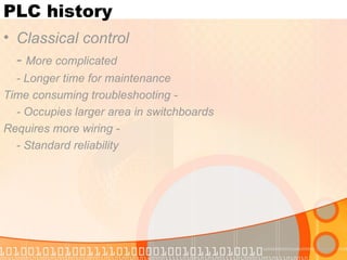
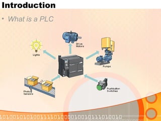
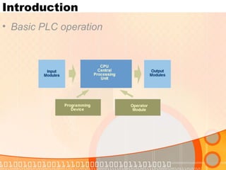
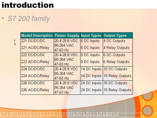
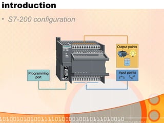
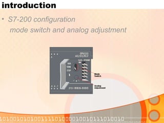
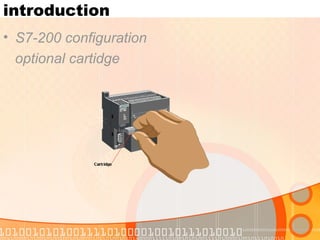
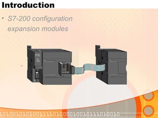
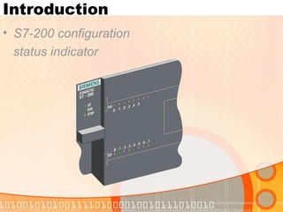
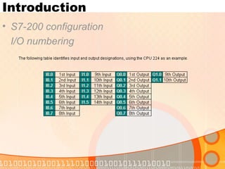
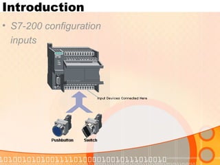
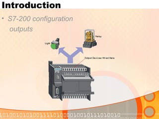
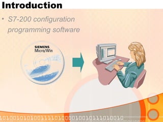
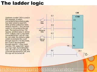
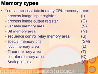
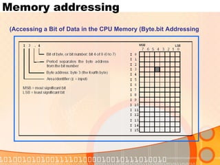
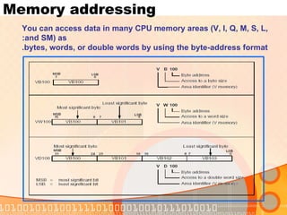
The document provides an overview of a Siemens S7-200 PLC training course. It discusses the history and advantages of PLCs over classical control systems. It then outlines the course contents which include introductions to PLC hardware configuration, programming languages, instructions like logic, timers, counters, and memory types. It also provides examples of programming concepts like inputs, outputs, timers, and counters.
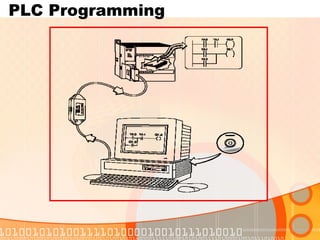
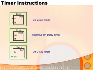
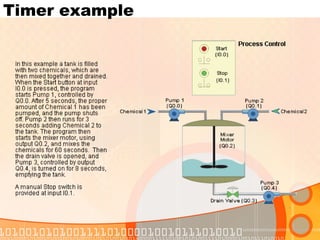
![Memory types Process-image input register (I) Format: Bit I[byte address].[bit address] I0.1 Byte, Word, Double Word I[size][starting byte address] IB4 Process-image output register (Q) Format: Bit Q[byte address].[bit address] Q1.1 Byte, Word, Double Word Q[size][starting byte address] QB5 Variable memory area (V) You can use V memory to: store intermediate results of the control logic operations. store other data pertaining to your process or task. Format: Bit V[byte address].[bit address] V10.2 Byte, Word, Double Word V[size][starting byte address] VW100](https://image.slidesharecdn.com/plcsiemenstrainingnotes-090415065750-phpapp01/85/Plc-Siemens-Training-Notes-55-320.jpg)
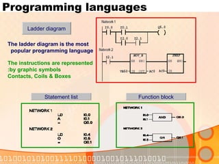
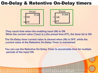
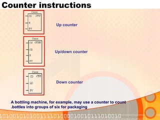
![Memory types Sequence control relay area (S) They are used to organize machine operations or steps into equivalent program segments. SCRs allow logical segmentation of the control Format: Bit S[byte address].[bit address] S3.1 Byte, Word, Double Word S[size][starting byte address] SB4 Special memory bits (SM) The SM bits provide a means for communicating information between the CPU and your program. You can use these bits to select and control some of the special functions of the S7-200 CPU, such as: • A bit that turns on for the first scan cycle • Bits that toggle at fixed rates • Bits that show the status of math or operational instructions Format: Bit SM[byte address].[bit address] SM0.1 Byte, Word, Double Word SM[size][starting byte address] SMB86](https://image.slidesharecdn.com/plcsiemenstrainingnotes-090415065750-phpapp01/85/Plc-Siemens-Training-Notes-56-320.jpg)
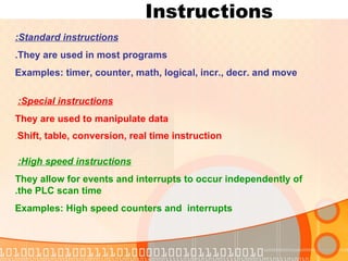
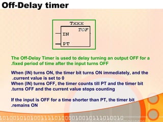
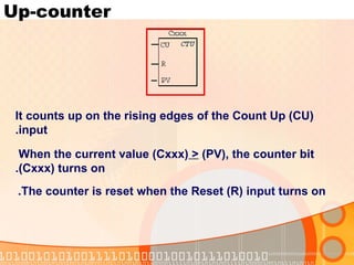
![Memory types Local memory area (L) The S7-200 PLCs provide 64 bytes of local (L) memory of which 60 can be used as scratchpad memory or for passing formal parameters to subroutines. Format: Bit L [byte address].[bit address] L0.0 Byte, Word, Double Word L [size] [starting byte address] LB33](https://image.slidesharecdn.com/plcsiemenstrainingnotes-090415065750-phpapp01/85/Plc-Siemens-Training-Notes-57-320.jpg)
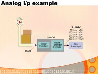
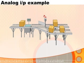
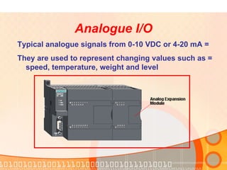
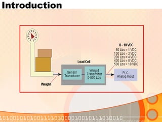
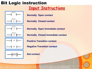
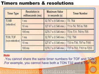
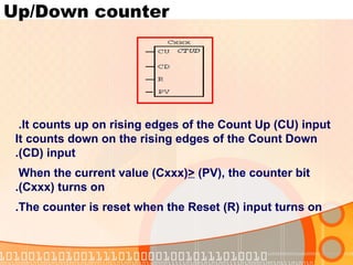
![Memory types Analog inputs (AI) The S7-200 converts a real-world, analog value (such as temperature or voltage) into a word-length (16-bit) digital value. You access these values by the area identifier (AI), size of the data (W), and the starting byte address. Since analog inputs are words and always start on even-number bytes (such as 0, 2, or 4), you access them with even-number byte addresses (such as AIW0, AIW2, or AIW4),as shown in Figure Analog input values are read-only values. Format: AIW [starting byte address] AIW4](https://image.slidesharecdn.com/plcsiemenstrainingnotes-090415065750-phpapp01/85/Plc-Siemens-Training-Notes-58-320.jpg)
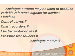
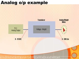
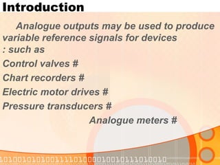
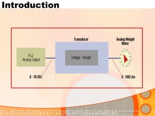
![Memory types The S7-200 converts a word-length (16-bit) digital value into a current or voltage, proportional to the digital value (such as for a current or voltage). You write these values by the area identifier (AQ), size of the data (W), and the starting by address. Since analog outputs are words and always start on even-number bytes (such as 0, 2, or 4), you write them with even-number byte addresses (AQW0, AQW2, AQW4), Format: AQW [starting byte address] AQW4 Analog outputs (AQ)](https://image.slidesharecdn.com/plcsiemenstrainingnotes-090415065750-phpapp01/85/Plc-Siemens-Training-Notes-59-320.jpg)