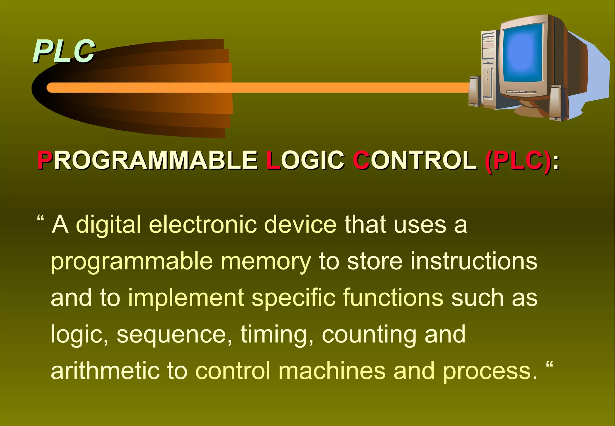
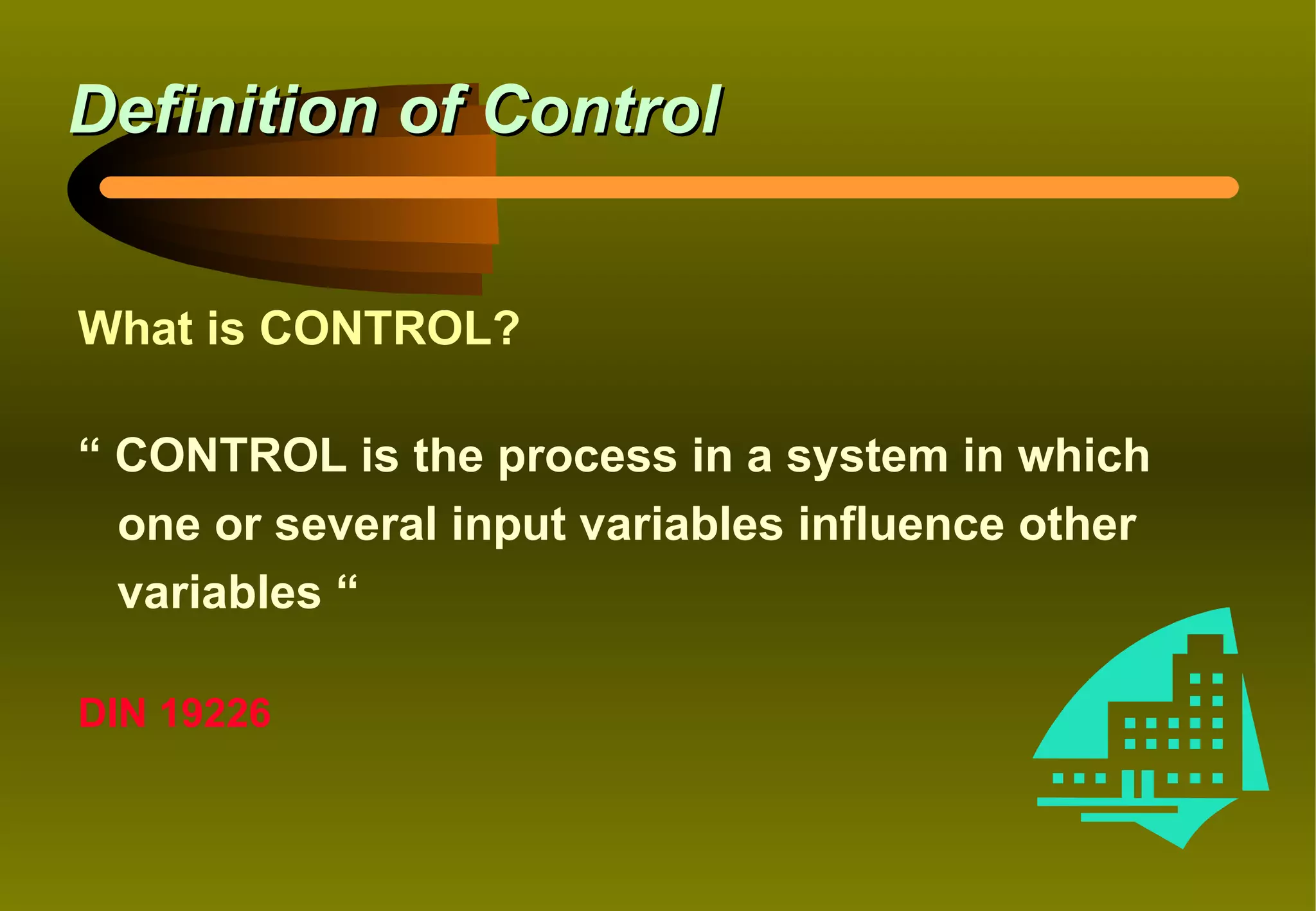
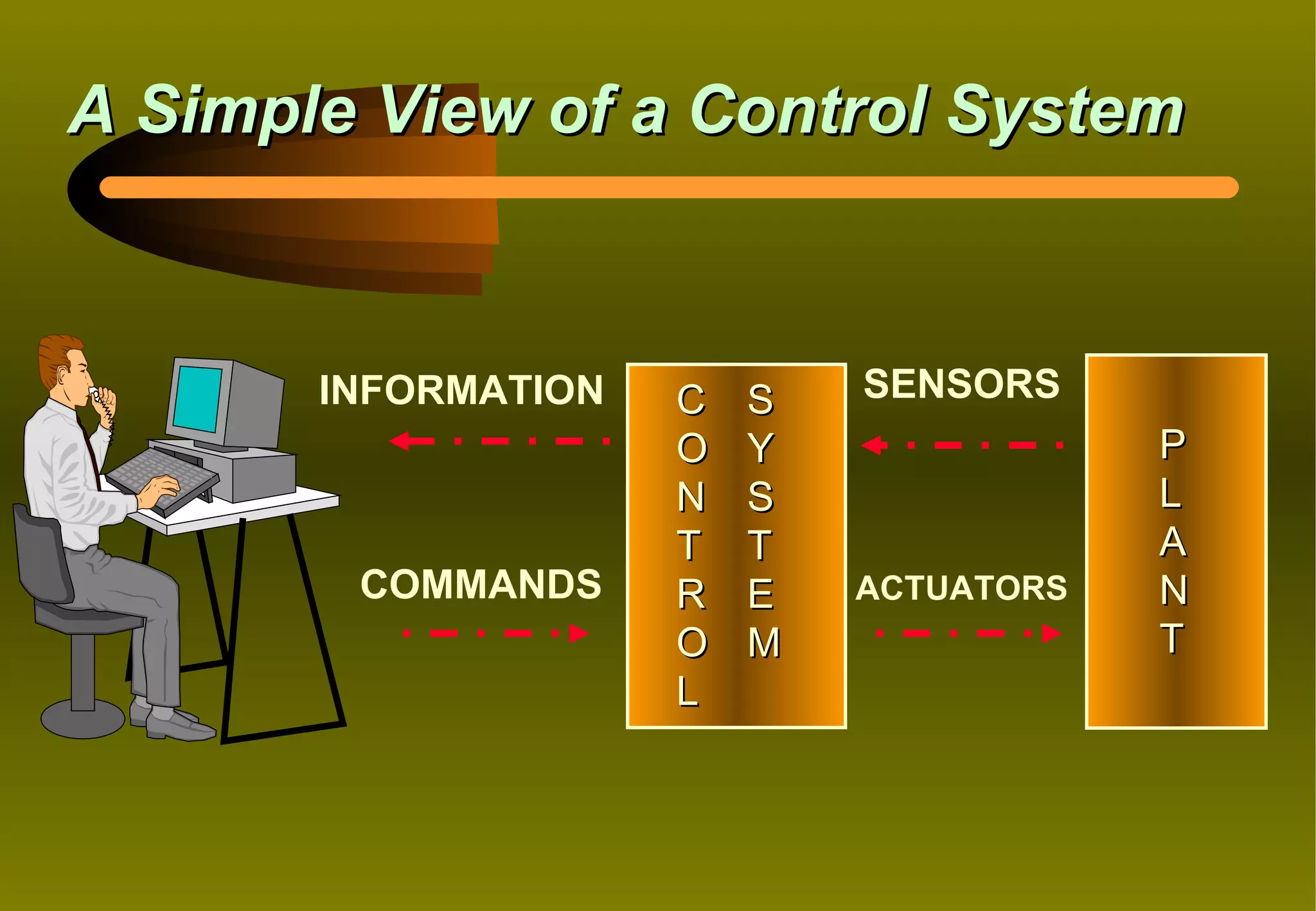
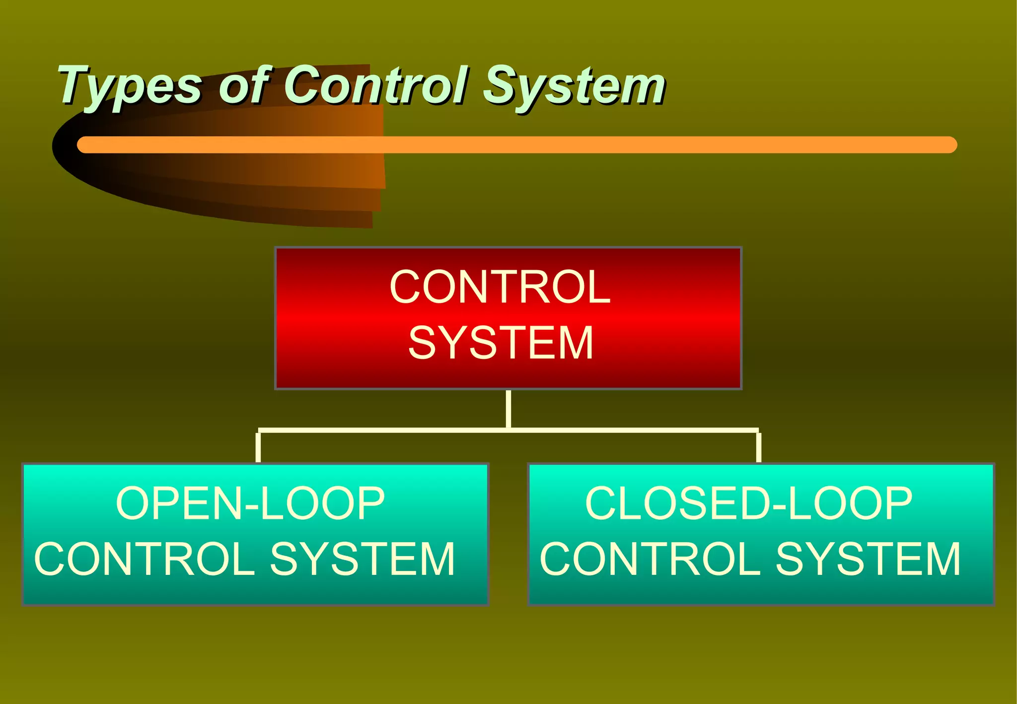
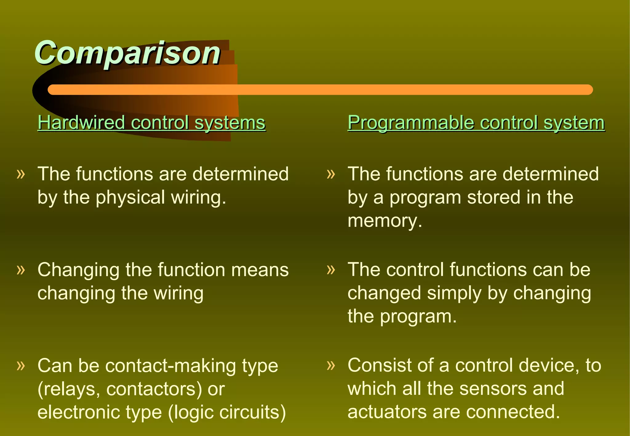
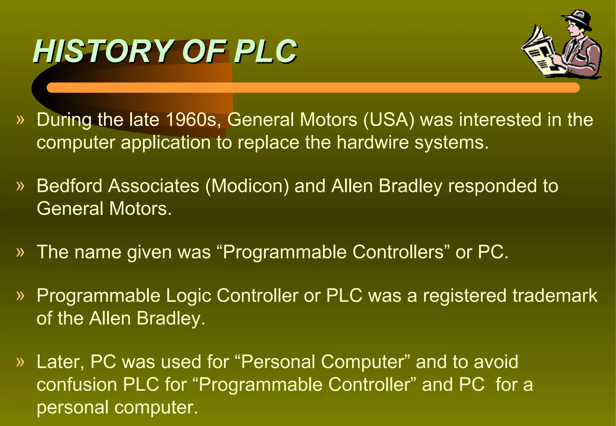
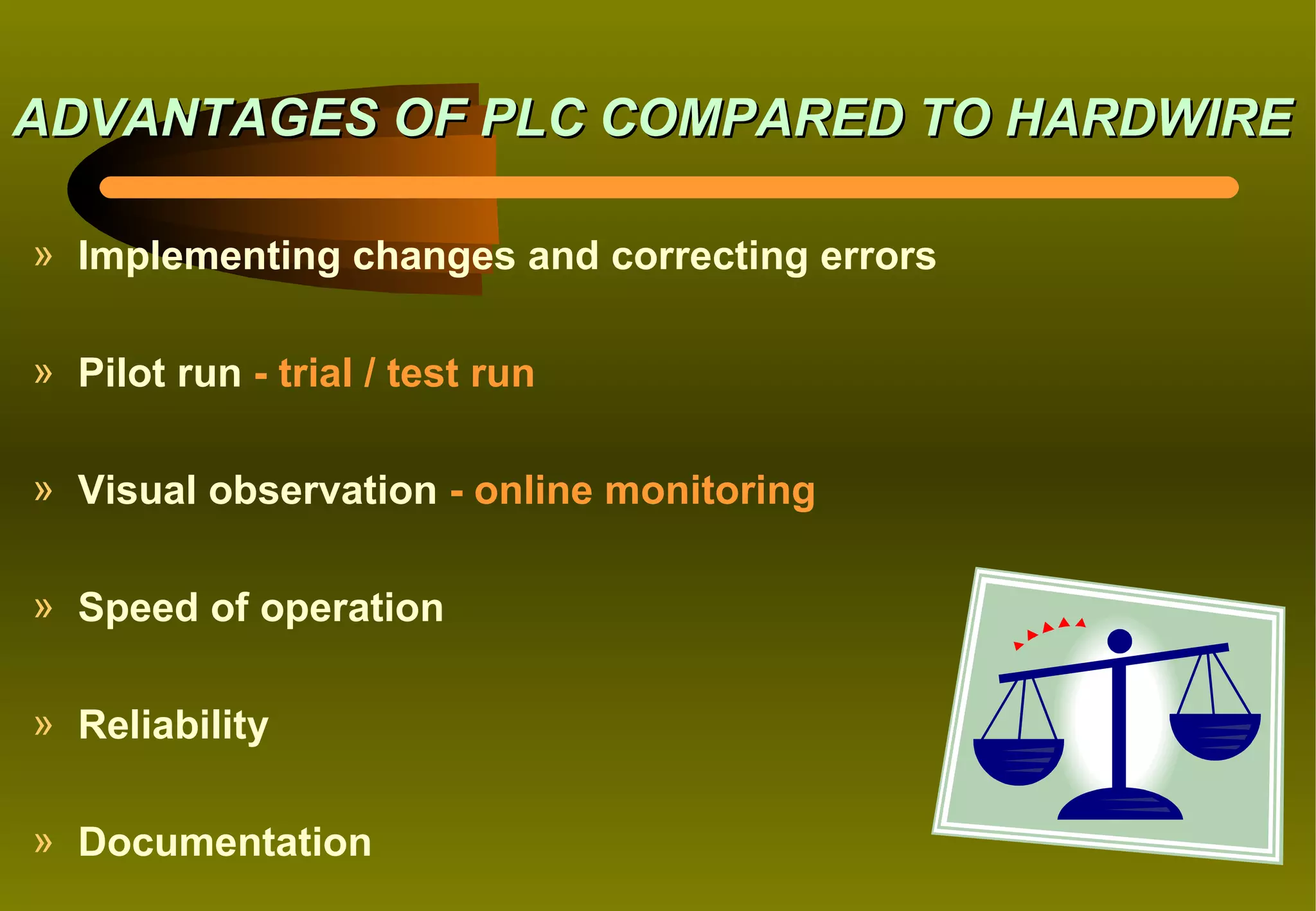
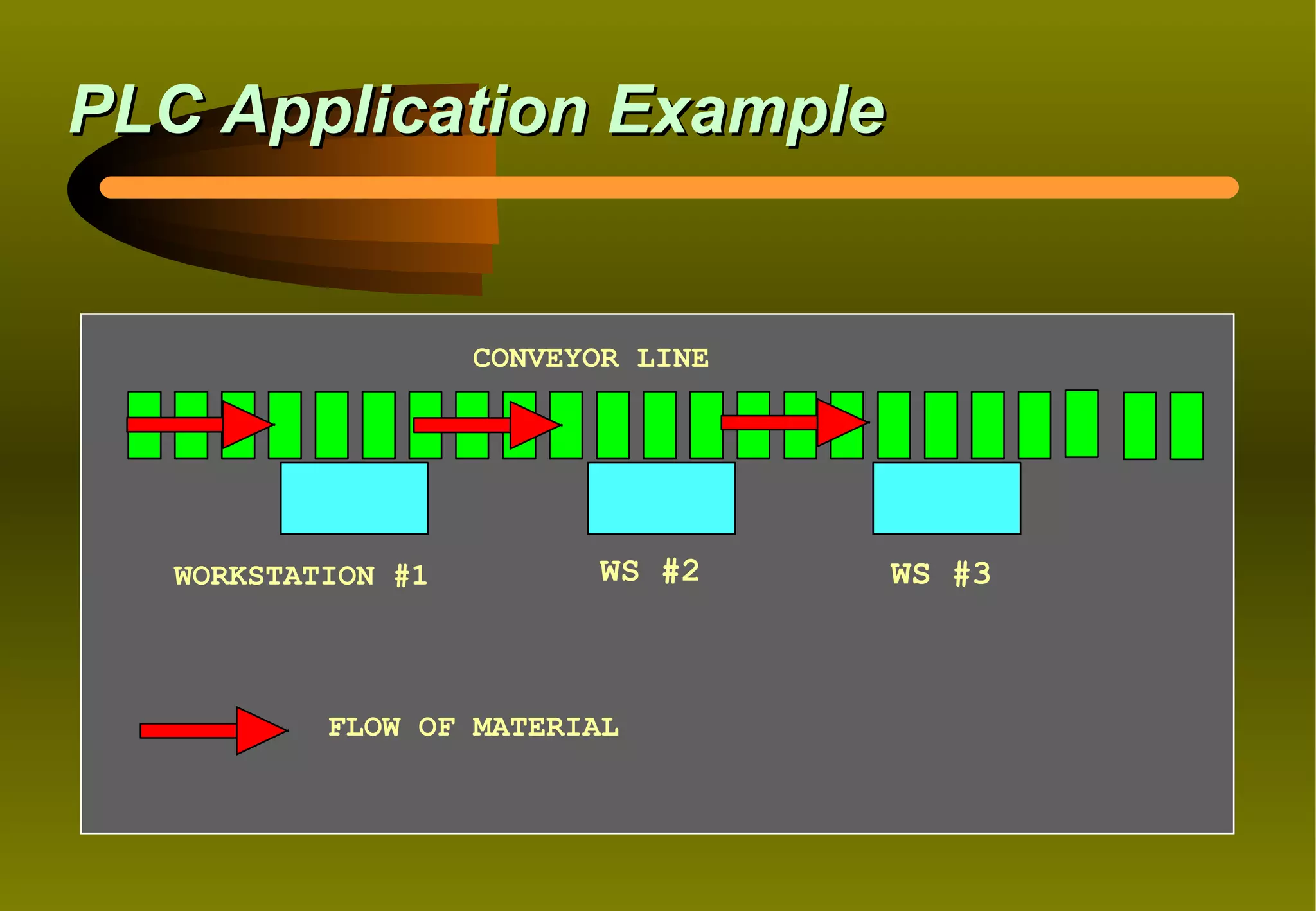
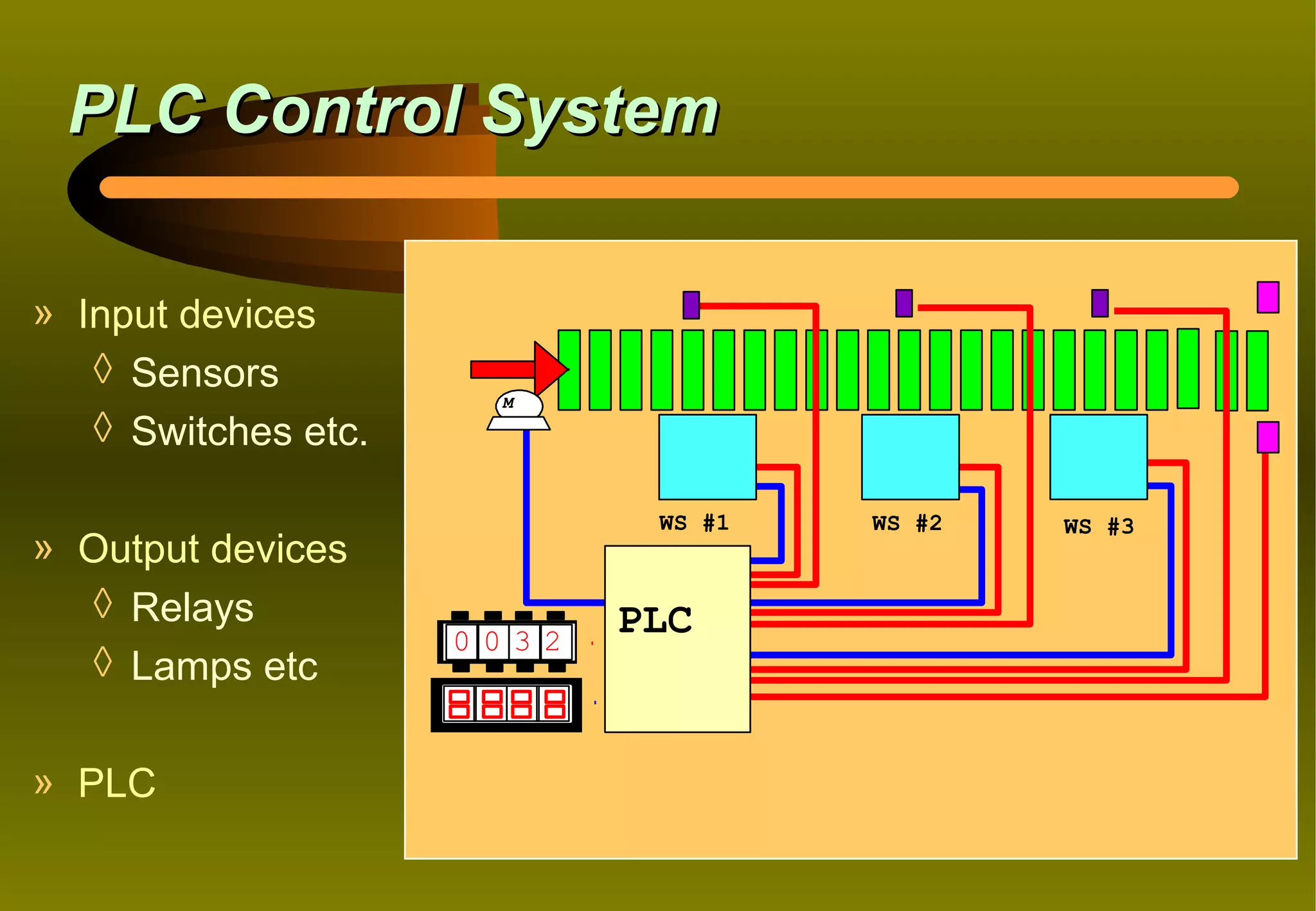
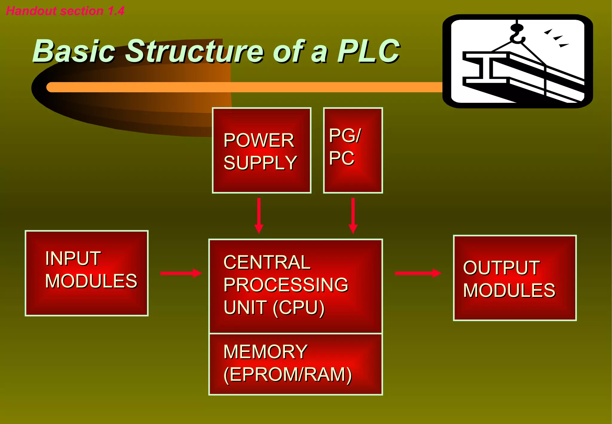
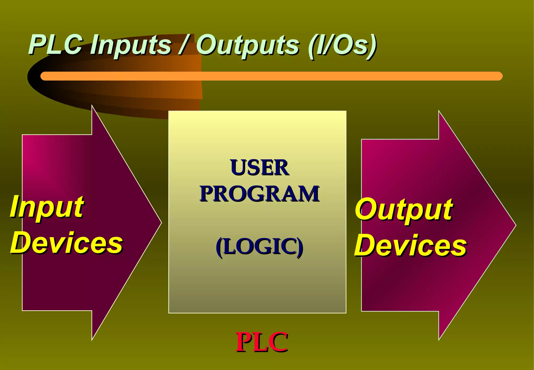
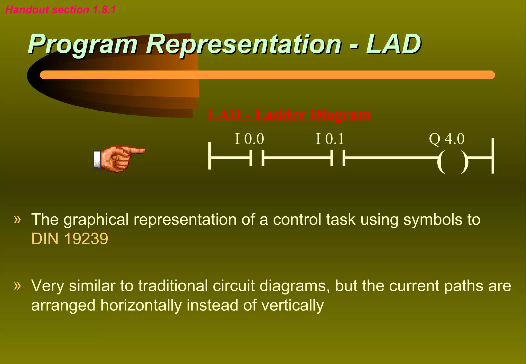
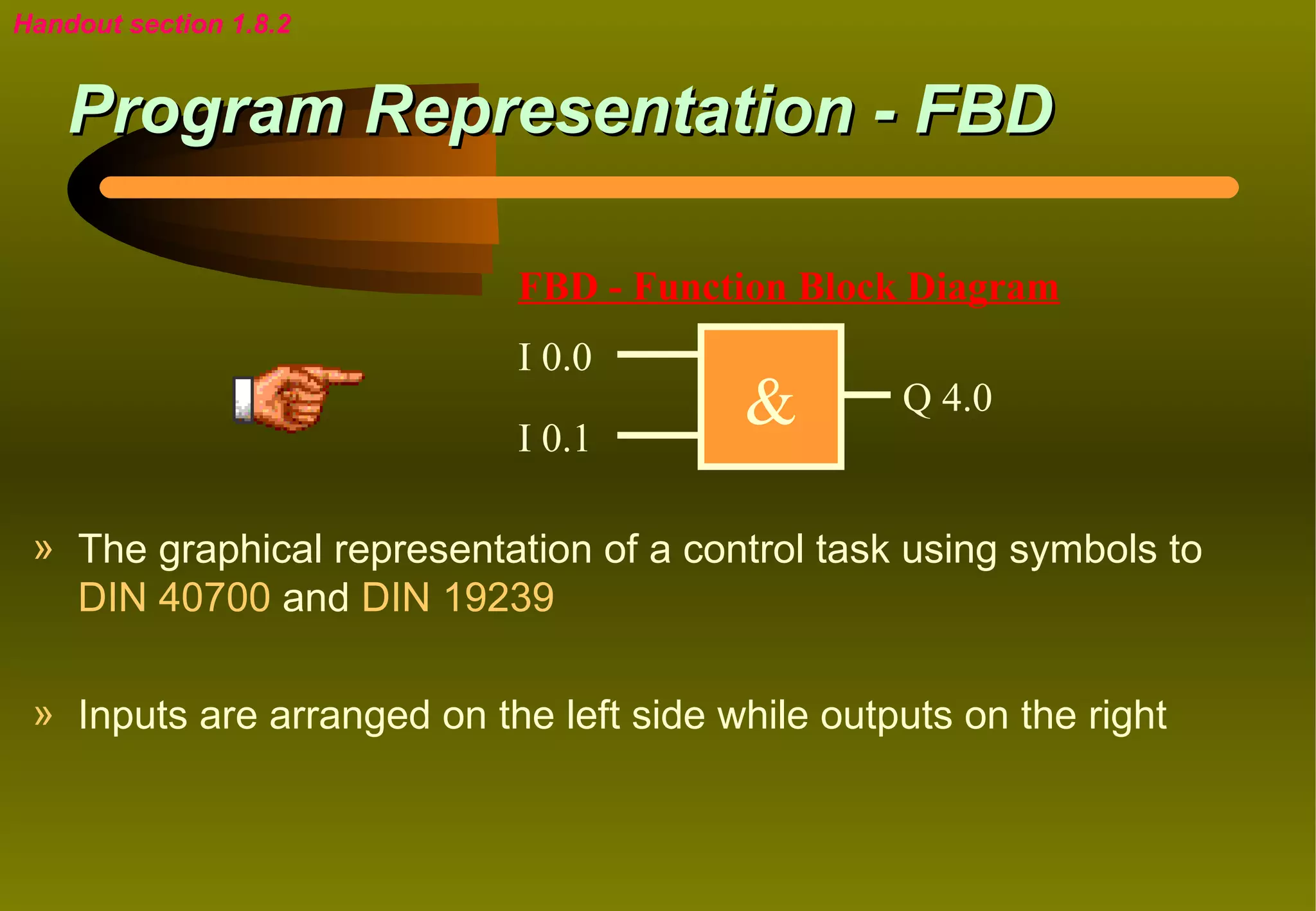
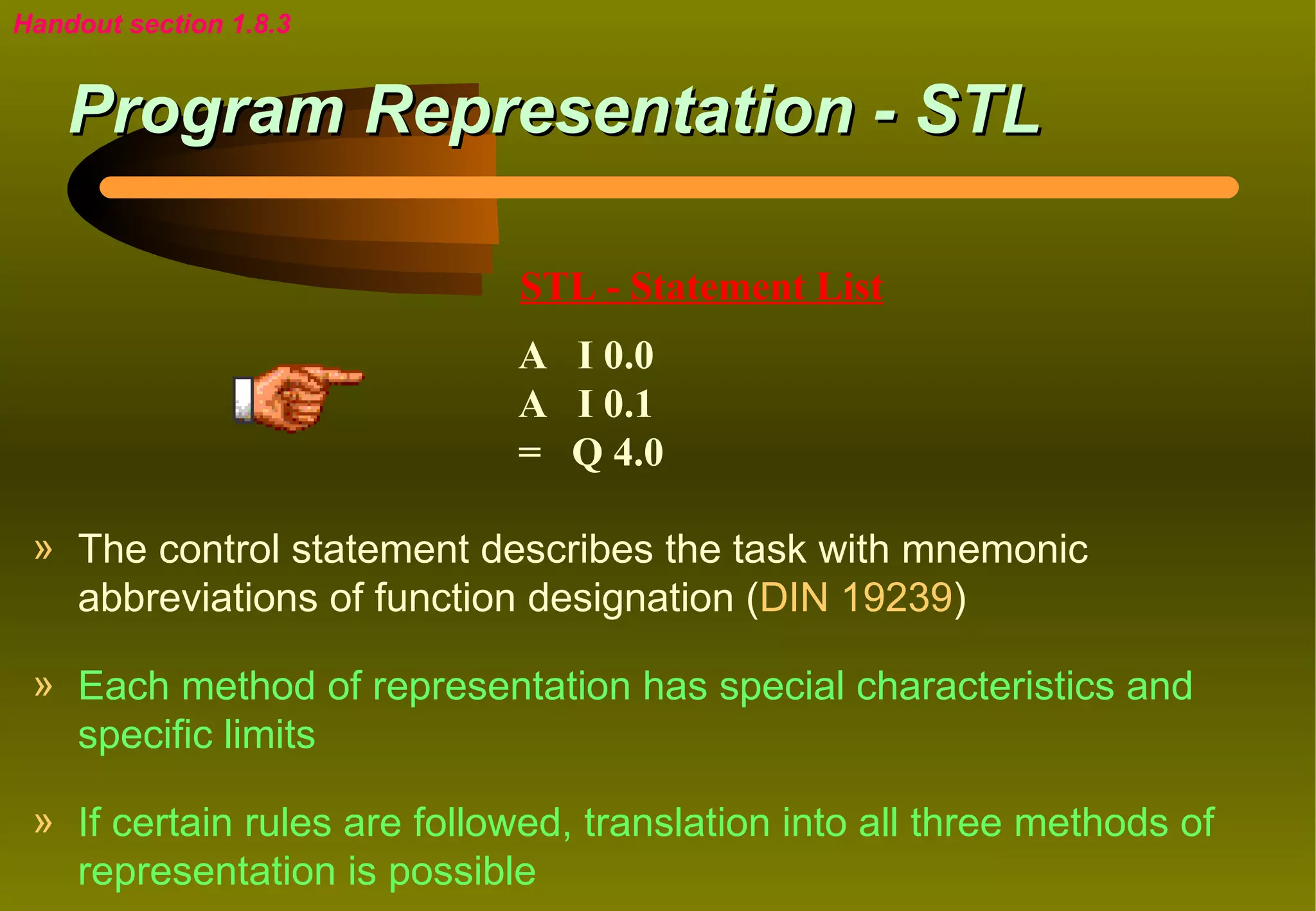
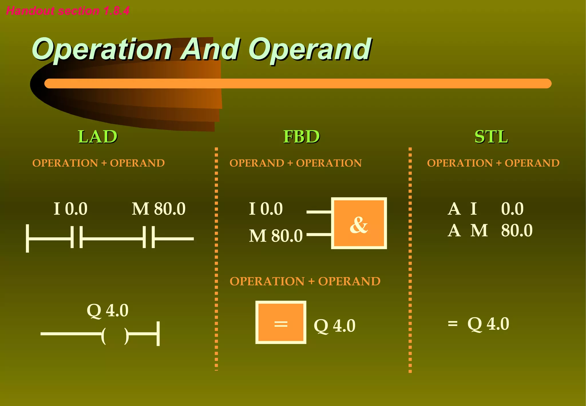
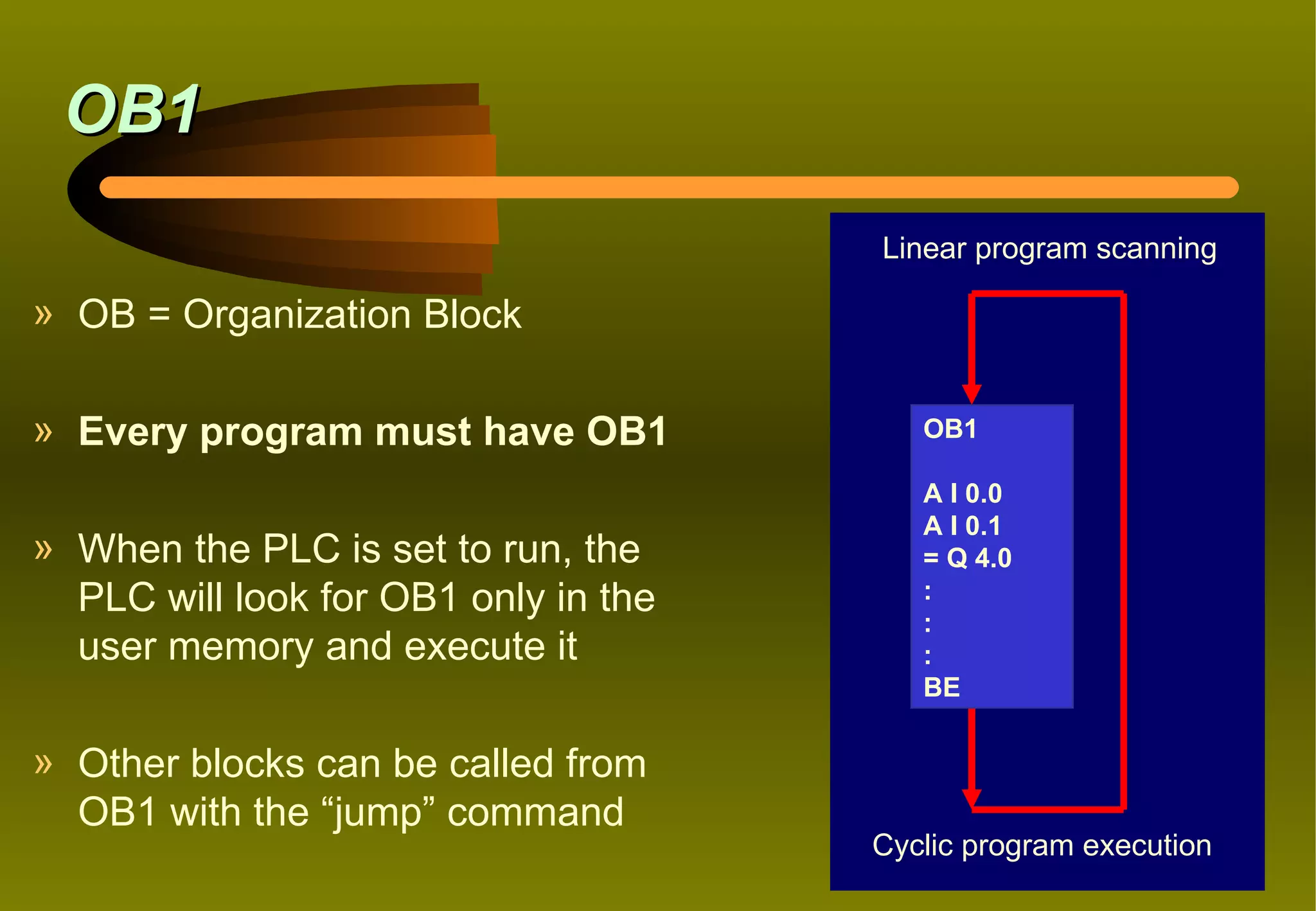
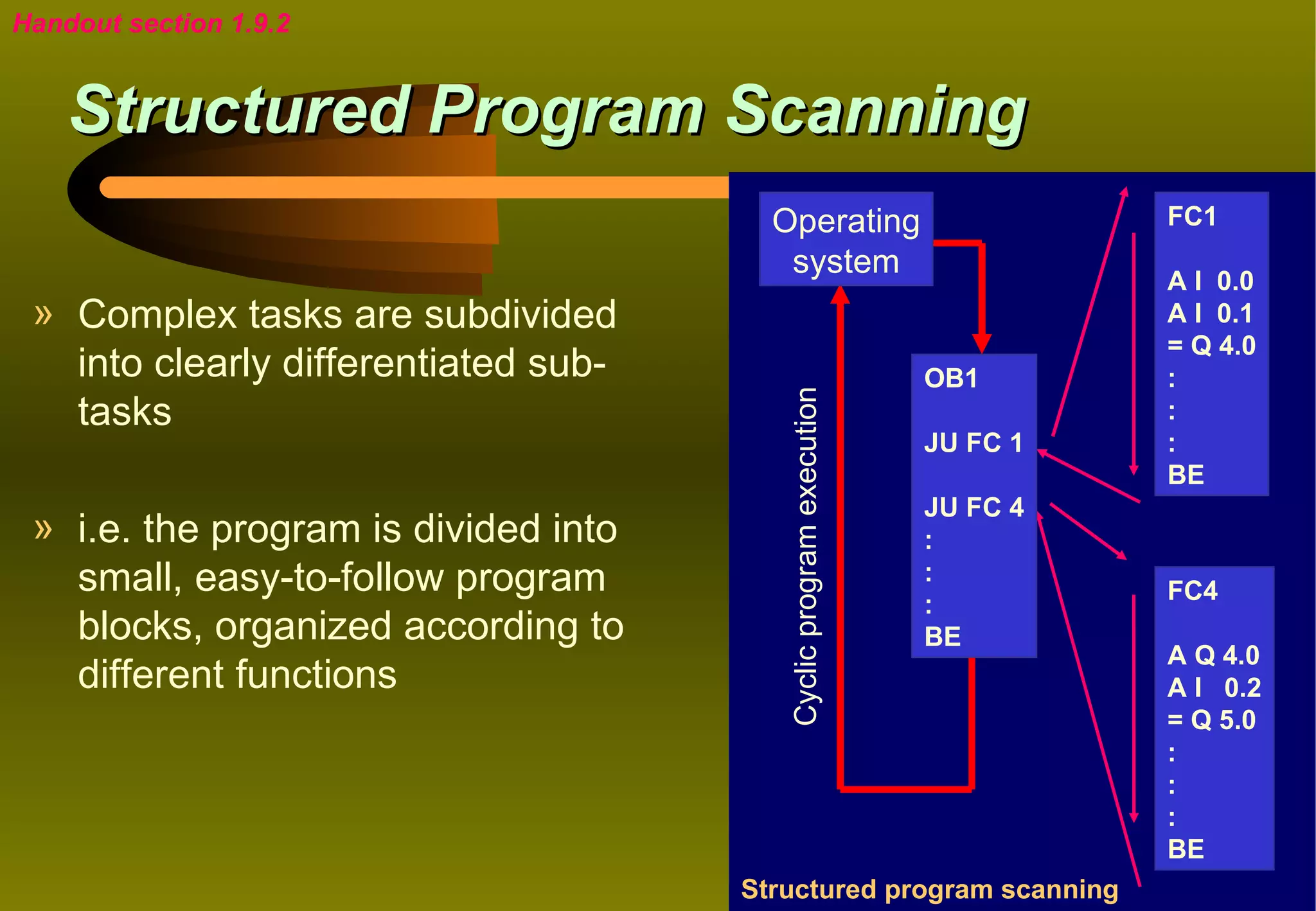
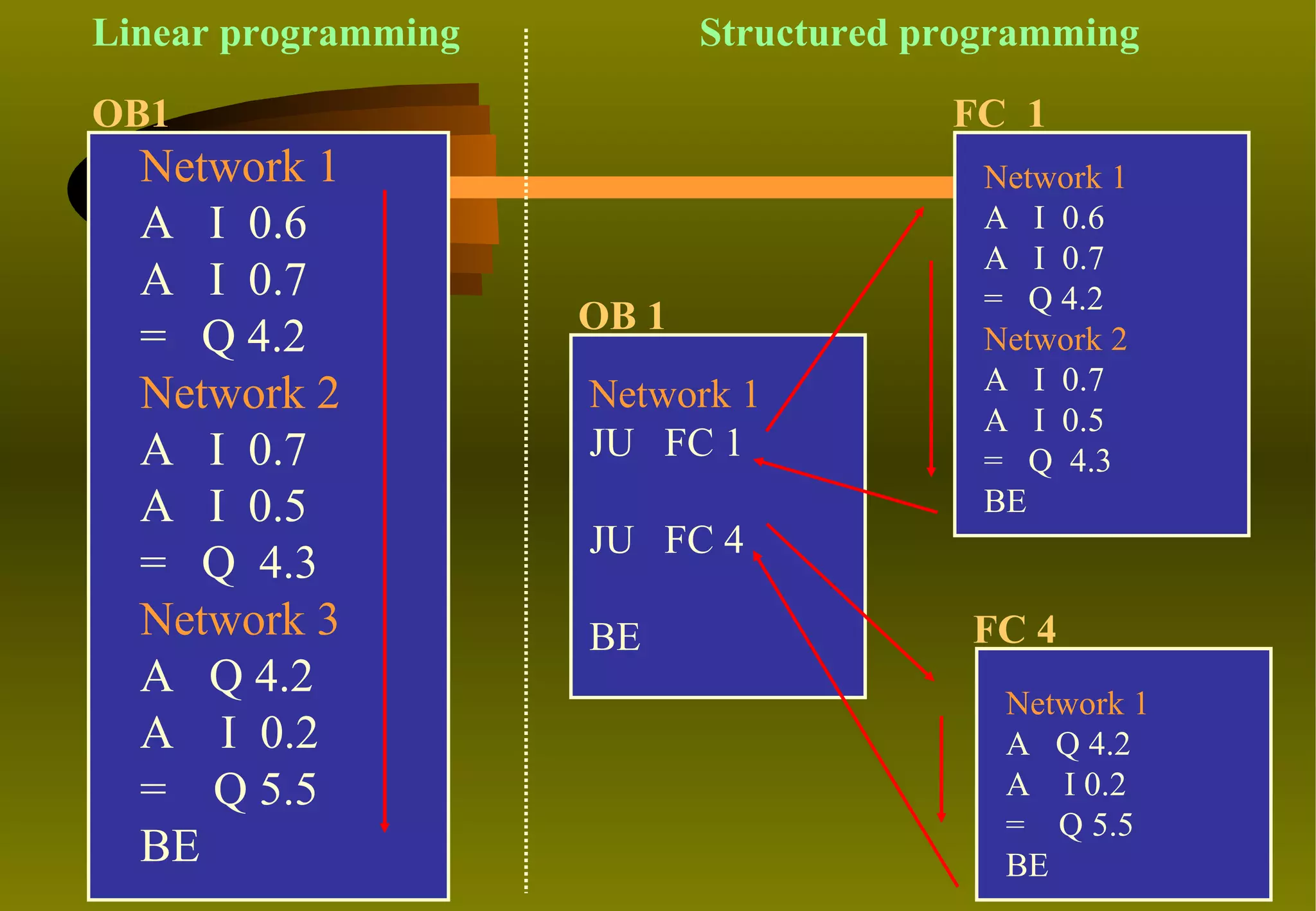
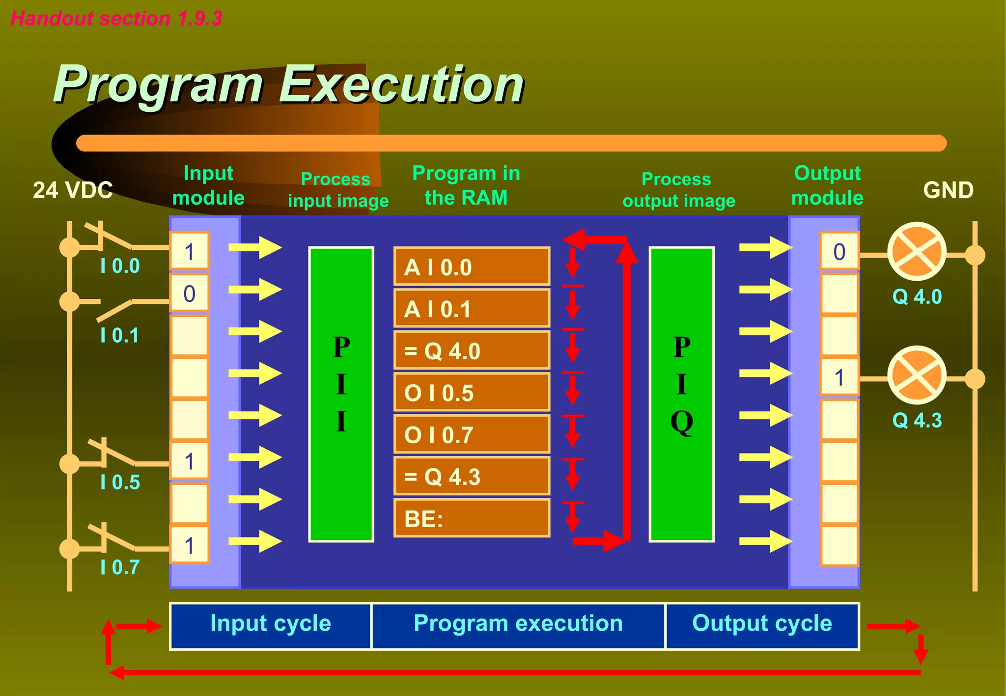
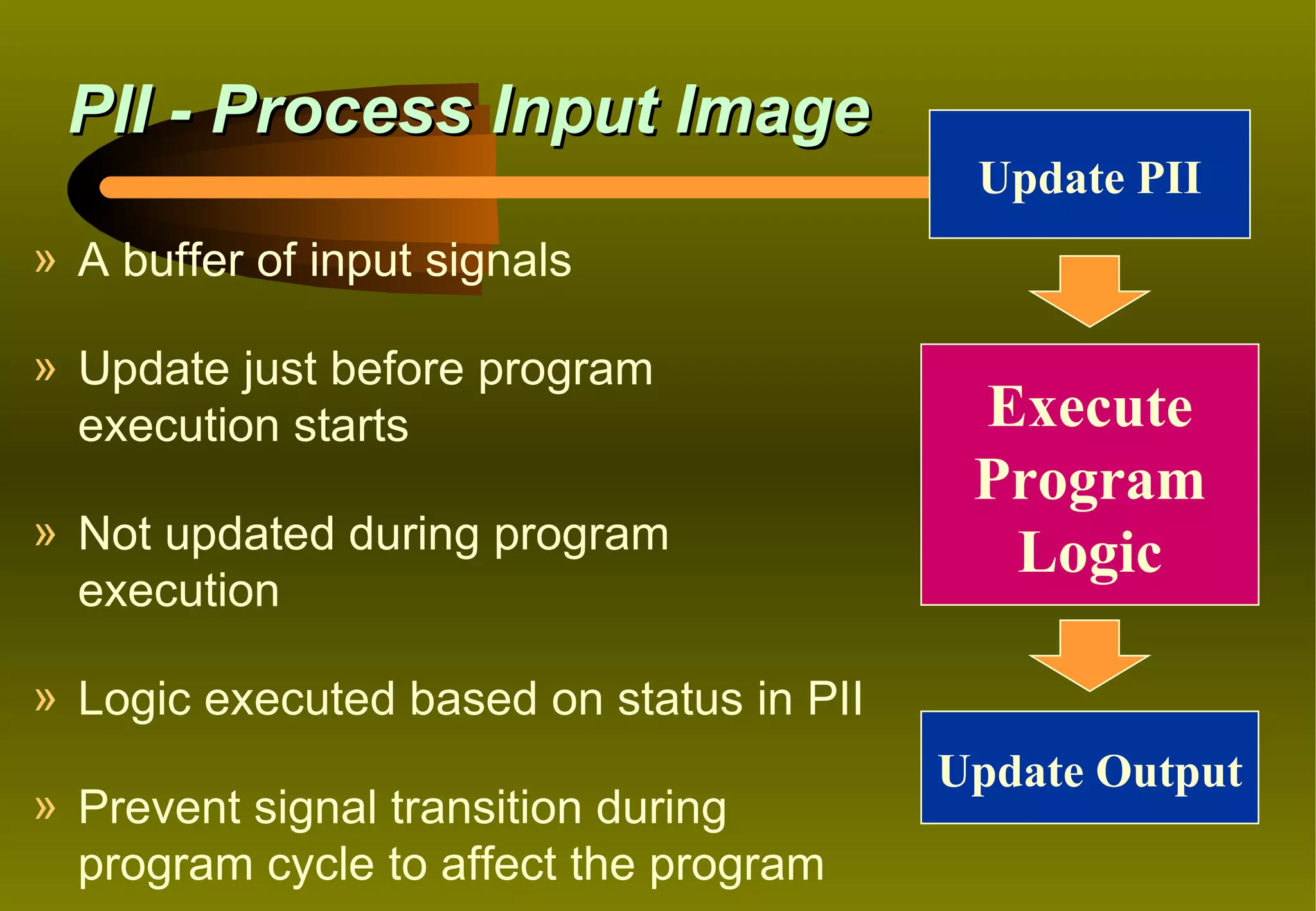
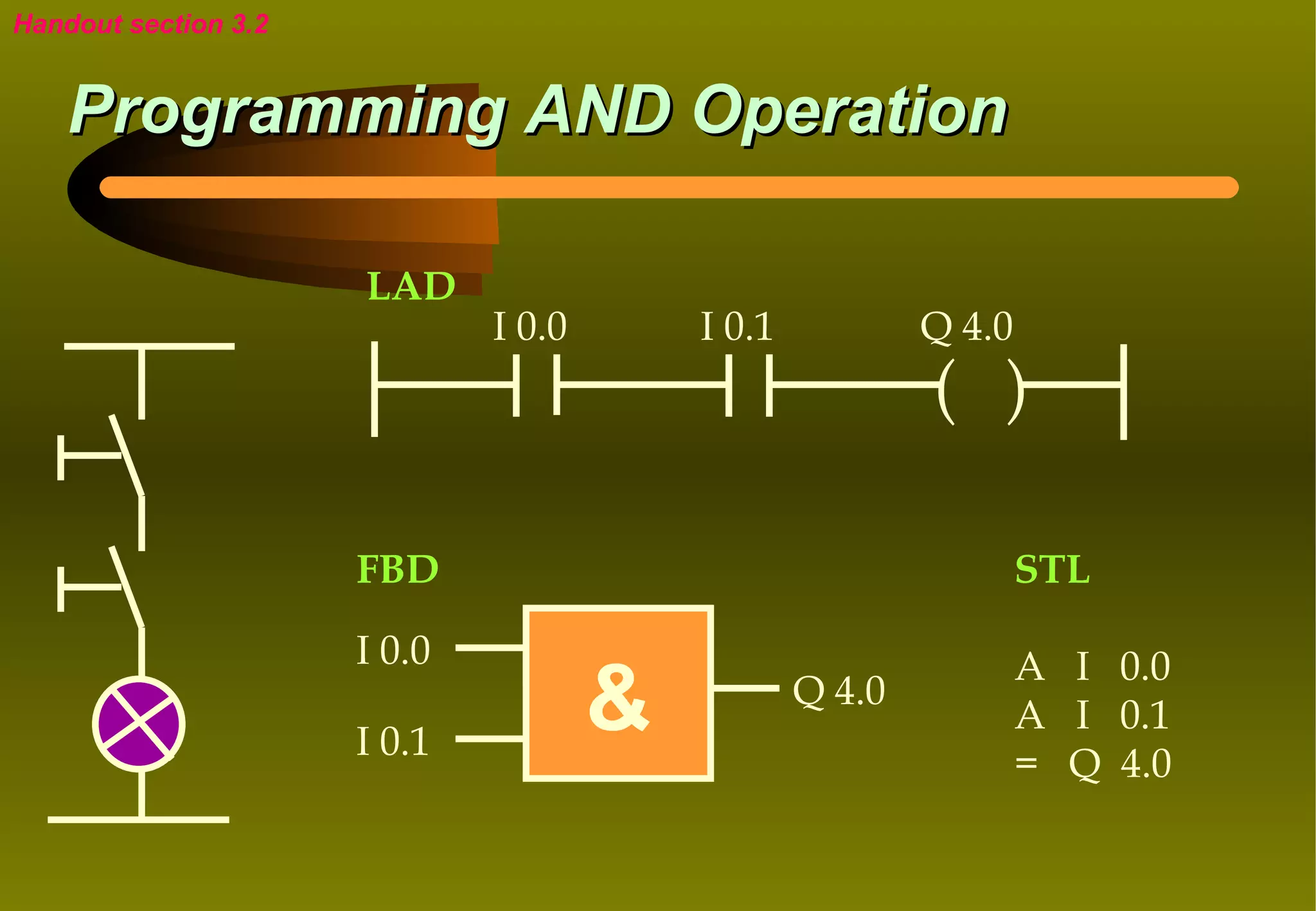
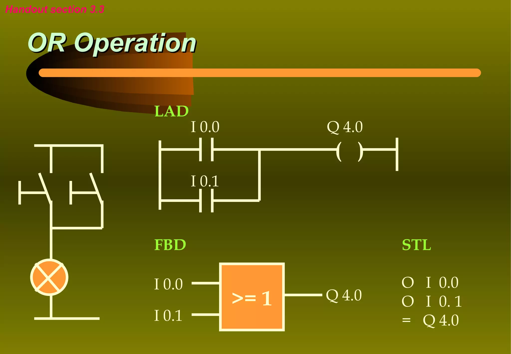
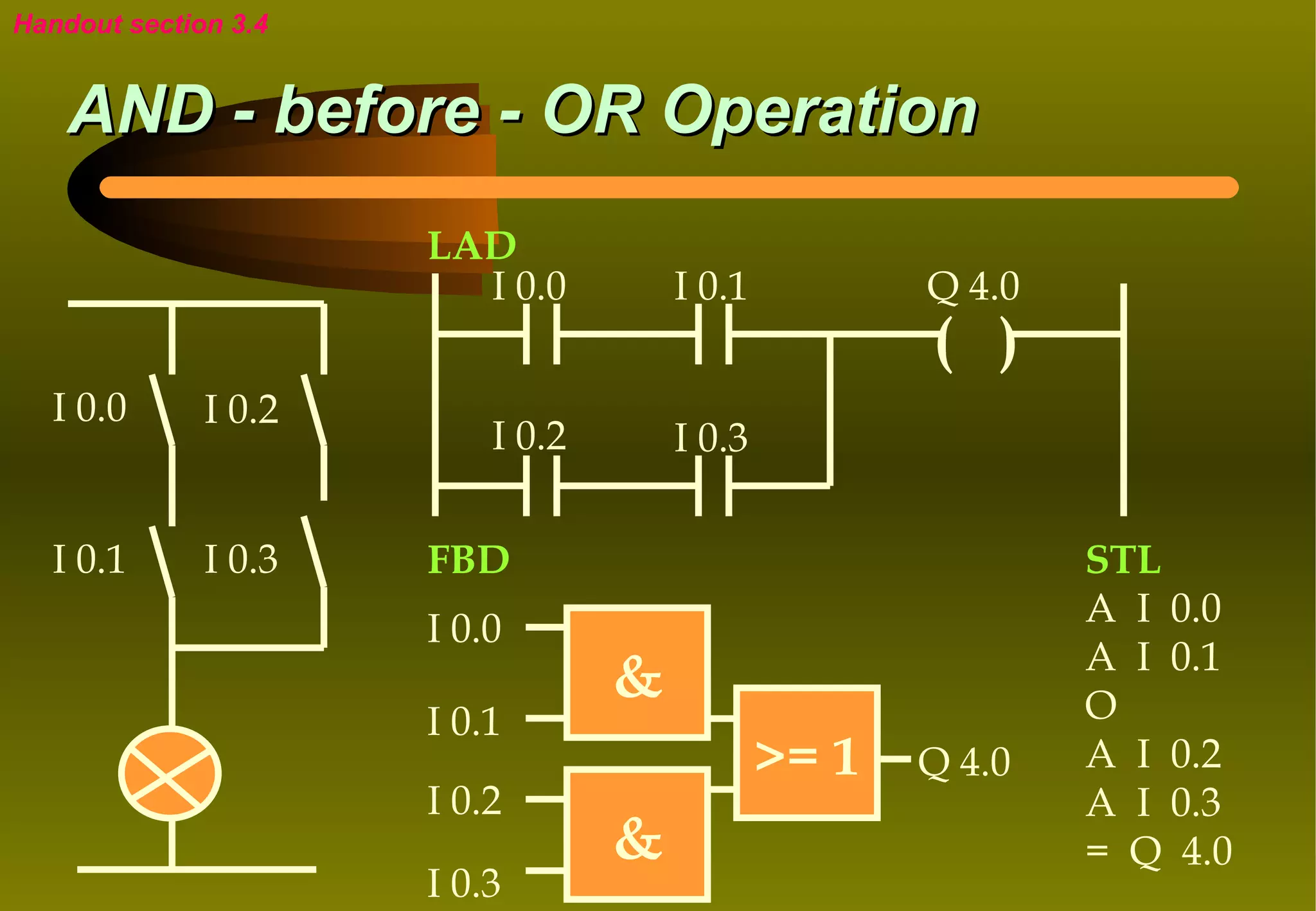
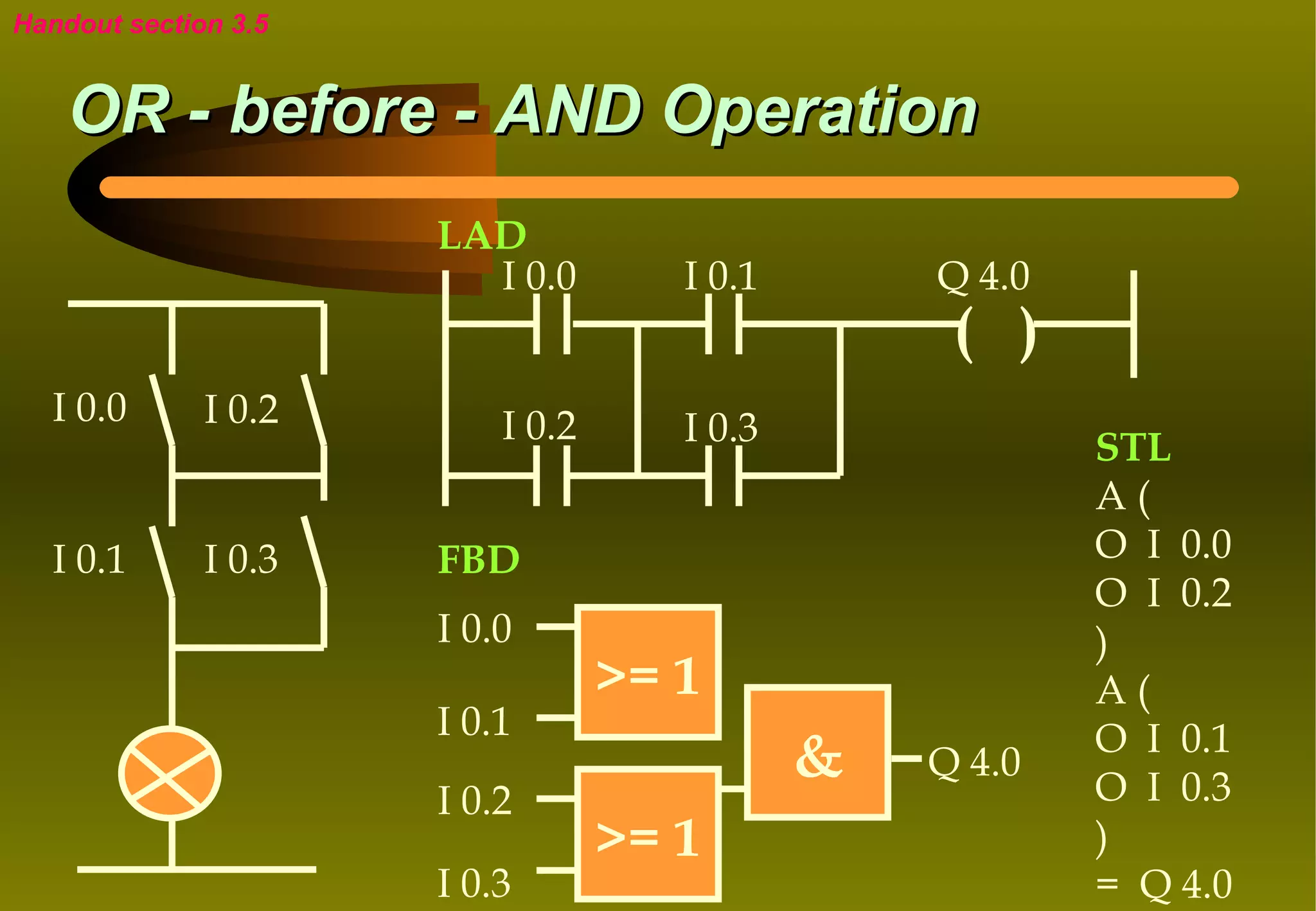
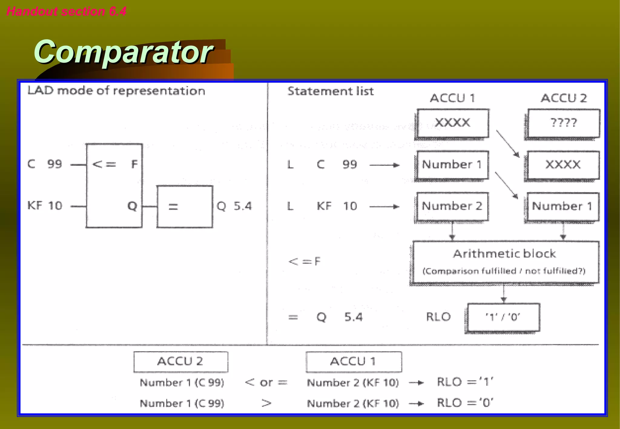
This document provides an introduction to programmable logic control (PLC) and Siemens SIMATIC S7 PLCs. It outlines the module objectives, assessment criteria, and topics to be covered including basic PLC components, programming methods, and Siemens STEP 7 software functions. The key topics covered are the basic principles of PLCs and control systems, PLC components and architecture, input/output modules, programming representations like LAD and FBD, and program execution methods.
PowerPoint Presentation on Industrial Automation In which we discuss About PLCs, SCADA,HMI,VFD and various tools of Automation which is used in Industries.
Like Comment & Share
An introduction to PLC languages - Instruction Language (IL) , Functional Block Diagram (FBD) , Ladder Logic Diagram (LD) and Sequential Function Chart (SFC).
(Download and open with Adobe Reader to see animations)
A Programmable Logic Controller (PLC) or Programmable Controller is an electronic device used for Automation of industrial processes, such as control of machinery on factory assembly lines.
Seminar Presentation on Programmeble Logic Controller , By an Engineering Student For doing Professional Presentation like Business Presentation, Industrial Use
PLC Ladder Diagram basics, with two solved examples
For more information go to
http://shrutizpresentations.blogspot.in/2014/04/plc-ladder-diagram-basics.html
Seminar Presentation on Programmeble Logic Controller , By an Engineering Student For doing Professional Presentation like Business Presentation, Industrial automation process,
Top Ten Programming Mistakes by People New to SiemensDMC, Inc.
DMC, a Siemens Solution Partner with the most S7 Certified Engineers in the United States, presented insights to people new to Siemens to help avoid common mistakes at the 2011 Siemens Automation Summit. Over the years we have encountered numerous applications written by novices and seen first-hand some of the more common errors made.
DMC, a Siemens Solution Partner with the most S7 Certified Engineers in the United States, recently shared some insights to people new to Siemens to help avoid common mistakes at the 2011 Siemens Automation Summit. Over the years we have encountered numerous applications written by novices and seen first-hand some of the more common errors made.
Unlock full featured course with 250+ Video Lectures at 20% Discount for "Learn 5 PLC's in a Day" lifetime E-Learning course for 39 USD only: https://www.udemy.com/nfi-plc-online-leaning/?couponCode=slideshare2016
Enroll for Advanced Industrial Automation Training with PLC, HMI and Drive Combo with 300+ Video Lecture for 69.3 USD only: http://online.nfiautomation.org/catalog/1769?couponCode=LEARNING_MADE_EASY
A PLC is a digital operating electronic apparatus.
Which uses a programmable memory for internal storage of instruction for implementing specific function such as logic, sequencing, timing, counting and arithmetic to control through analog or digital input/output modules various types of machines or process.
Model Attribute Check Company Auto PropertyCeline George
In Odoo, the multi-company feature allows you to manage multiple companies within a single Odoo database instance. Each company can have its own configurations while still sharing common resources such as products, customers, and suppliers.
The French Revolution, which began in 1789, was a period of radical social and political upheaval in France. It marked the decline of absolute monarchies, the rise of secular and democratic republics, and the eventual rise of Napoleon Bonaparte. This revolutionary period is crucial in understanding the transition from feudalism to modernity in Europe.
For more information, visit-www.vavaclasses.com
Embracing GenAI - A Strategic ImperativePeter Windle
Artificial Intelligence (AI) technologies such as Generative AI, Image Generators and Large Language Models have had a dramatic impact on teaching, learning and assessment over the past 18 months. The most immediate threat AI posed was to Academic Integrity with Higher Education Institutes (HEIs) focusing their efforts on combating the use of GenAI in assessment. Guidelines were developed for staff and students, policies put in place too. Innovative educators have forged paths in the use of Generative AI for teaching, learning and assessments leading to pockets of transformation springing up across HEIs, often with little or no top-down guidance, support or direction.
This Gasta posits a strategic approach to integrating AI into HEIs to prepare staff, students and the curriculum for an evolving world and workplace. We will highlight the advantages of working with these technologies beyond the realm of teaching, learning and assessment by considering prompt engineering skills, industry impact, curriculum changes, and the need for staff upskilling. In contrast, not engaging strategically with Generative AI poses risks, including falling behind peers, missed opportunities and failing to ensure our graduates remain employable. The rapid evolution of AI technologies necessitates a proactive and strategic approach if we are to remain relevant.
How to Make a Field invisible in Odoo 17Celine George
It is possible to hide or invisible some fields in odoo. Commonly using “invisible” attribute in the field definition to invisible the fields. This slide will show how to make a field invisible in odoo 17.
The Roman Empire A Historical Colossus.pdfkaushalkr1407
The Roman Empire, a vast and enduring power, stands as one of history's most remarkable civilizations, leaving an indelible imprint on the world. It emerged from the Roman Republic, transitioning into an imperial powerhouse under the leadership of Augustus Caesar in 27 BCE. This transformation marked the beginning of an era defined by unprecedented territorial expansion, architectural marvels, and profound cultural influence.
The empire's roots lie in the city of Rome, founded, according to legend, by Romulus in 753 BCE. Over centuries, Rome evolved from a small settlement to a formidable republic, characterized by a complex political system with elected officials and checks on power. However, internal strife, class conflicts, and military ambitions paved the way for the end of the Republic. Julius Caesar’s dictatorship and subsequent assassination in 44 BCE created a power vacuum, leading to a civil war. Octavian, later Augustus, emerged victorious, heralding the Roman Empire’s birth.
Under Augustus, the empire experienced the Pax Romana, a 200-year period of relative peace and stability. Augustus reformed the military, established efficient administrative systems, and initiated grand construction projects. The empire's borders expanded, encompassing territories from Britain to Egypt and from Spain to the Euphrates. Roman legions, renowned for their discipline and engineering prowess, secured and maintained these vast territories, building roads, fortifications, and cities that facilitated control and integration.
The Roman Empire’s society was hierarchical, with a rigid class system. At the top were the patricians, wealthy elites who held significant political power. Below them were the plebeians, free citizens with limited political influence, and the vast numbers of slaves who formed the backbone of the economy. The family unit was central, governed by the paterfamilias, the male head who held absolute authority.
Culturally, the Romans were eclectic, absorbing and adapting elements from the civilizations they encountered, particularly the Greeks. Roman art, literature, and philosophy reflected this synthesis, creating a rich cultural tapestry. Latin, the Roman language, became the lingua franca of the Western world, influencing numerous modern languages.
Roman architecture and engineering achievements were monumental. They perfected the arch, vault, and dome, constructing enduring structures like the Colosseum, Pantheon, and aqueducts. These engineering marvels not only showcased Roman ingenuity but also served practical purposes, from public entertainment to water supply.
Operation “Blue Star” is the only event in the history of Independent India where the state went into war with its own people. Even after about 40 years it is not clear if it was culmination of states anger over people of the region, a political game of power or start of dictatorial chapter in the democratic setup.
The people of Punjab felt alienated from main stream due to denial of their just demands during a long democratic struggle since independence. As it happen all over the word, it led to militant struggle with great loss of lives of military, police and civilian personnel. Killing of Indira Gandhi and massacre of innocent Sikhs in Delhi and other India cities was also associated with this movement.
2. ASSESSMENT
» Practical Test 1 – 20%
» Practical Test 2 – 20%
» Assignment – 20%
» Final Exam – 30%
» Key Qualification – 10%
3. MODULE OBJECTIVES
Upon completion of this course, the participants will be able to:
» explain the basic ideas on PLC such as PLC components’
signaling, I/O addressing and program execution;
» apply PLC programming method such as LAD, FBD and STL using
Siemens STEP 7 software;
» define and explain Siemens STEP 7 PLC software such as RS,
timers, counters, load and transfer commands, comparisons and
arithmetic functions.
5. PLC
PROGRAMMABLE LOGIC CONTROL (PLC):
“ A digital electronic device that uses a
programmable memory to store instructions
and to implement specific functions such as
logic, sequence, timing, counting and
arithmetic to control machines and process. “
6. Definition of Control
What is CONTROL?
“ CONTROL is the process in a system in which
one or several input variables influence other
variables “
DIN 19226
7. A Simple View of a Control System
INFORMATION C S SENSORS
O Y P
N S L
T T A
COMMANDS R E ACTUATORS N
O M T
L
8. Types of Control System
CONTROL
SYSTEM
OPEN-LOOP CLOSED-LOOP
CONTROL SYSTEM CONTROL SYSTEM
9. Open-loop Control System
In open-loop control systems, output variables are
influenced by the input variables.
L
N
10. Closed-loop Control System
It is characterized by continuous comparison of the
desired value (or set point) with the actual value of the
controlled variable.
L
Xi > Xs C
Xi - Required value
Xi
Xs - Actual value Xs
Xi < Xs
N
11. Handout section 1.1
PLC and Conventional Control System
The essential difference between programmable
control and traditional control technology may be
summed up as follows:
» The functions are no longer determined by the wiring, but
rather by the program
» Programming is simplified to enable symbols familiar to
the control engineer to be used (contacts or logic graphic
symbols)
12. Handout section 1.3
Hardwire and PLC Wiring Diagrams
L 24 VDC
S1 S1 S2
S2 K1
PLC
K1 K1
N 0V
Hardwire PLC
13. Comparison
Hardwired control systems Programmable control system
» The functions are determined » The functions are determined
by the physical wiring. by a program stored in the
memory.
» Changing the function means » The control functions can be
changing the wiring changed simply by changing
the program.
» Can be contact-making type » Consist of a control device, to
(relays, contactors) or which all the sensors and
electronic type (logic circuits) actuators are connected.
14. HISTORY OF PLC
» During the late 1960s, General Motors (USA) was interested in the
computer application to replace the hardwire systems.
» Bedford Associates (Modicon) and Allen Bradley responded to
General Motors.
» The name given was “Programmable Controllers” or PC.
» Programmable Logic Controller or PLC was a registered trademark
of the Allen Bradley.
» Later, PC was used for “Personal Computer” and to avoid
confusion PLC for “Programmable Controller” and PC for a
personal computer.
15. ADVANTAGES OF PLC COMPARED TO HARDWIRE
» Implementing changes and correcting errors
» Pilot run - trial / test run
» Visual observation - online monitoring
» Speed of operation
» Reliability
» Documentation
19. Handout section 1.4
Basic Structure of a PLC
POWER PG/
SUPPLY PC
INPUT CENTRAL OUTPUT
MODULES PROCESSING MODULES
UNIT (CPU)
MEMORY
(EPROM/RAM)
20. PLC Inputs / Outputs (I/Os)
USER
PROGRAM
Input Output
Devices (LOGIC) Devices
PLC
21. Input Connections
» Input card
» Converter
Input ◊ field voltage to 5V
Devices acceptable by the CPU
22. Handout section 1.4.1
Input Interface / Module
From field wiring
Detection
Bridge
Signal
Conditioning
Logic Status
Threshold
Light
Decision
Opto-Isolation
Logic
To CPU / Memory
24. Handout section 1.4.2
Output Interface / Module
From CPU / Memory
Logic Status
Logic Light
Opto-Isolation
Switching
Circuitry
Protection
Circuitry
To field wiring
27. Input / Output Modules
» Digital input modules adapt digital signals e.g. from proximity
sensors
» Digital output modules convert the internal signal level of PLC into
digital process signals e.g. relays
» Analog input modules adapt analog process signals e.g. from
transducers
» Analog output modules convert internal digital values of the PLC to
analog process signals e.g. temperature controller
28. Handout section 1.4.3
Central Processing Unit (CPU)
What is a CPU?
» The “brain” of a PLC
» Controlled by a program called the executive or operating
system (OS)
» The executive is a collection of supervisory programs
permanently stored in memory
29. CPU
Four basic types of CPU operations:
» Input and output operation
» Arithmetic and logic
» Reading or changing contents of memory locations
» Jump operations
30. CPU
INTERNAL MEMORY
PROGRAM SUBMODULE
ACCUMULATOR MEMORY (EPROM/
(RAM) EEPROM/
RAM)
TIMERS,
COUNTERS,
Memory SERIAL
INTERFACE
PROCESSOR
PII PIQ
31. CPU
» The CPU reads in input signal states, processes the control
program and controls the outputs.
» The CPU provides internal Memory, timers and counters.
» Restart procedure can be preset and errors can be diagnosed
using the CPU’s LEDs.
» The overall Reset on the CPU is used to delete the contents of the
RAM.
» A PG or a Memory submodule is used to transfer the control
program to the CPU.
32. Handout section 1.4.4
Program Memory
Program memory
RAM (Random Access Memory) ROM (Read Only Memory)
• the memory contents can be • the memory contents can be
read and written (modified) read, but cannot be modified
• memory contents will be lost
when the supply voltage fails
33. Types of Program Memory
Program memory
Programmable Non-programmable
(Read-write memory)
Non-alterable
Alterable ROM / PROM
UV erasable Electrically erasable
EPROM / REPROM EEPROM / EAPROM
Semiconductor RAM Semiconductor
EEPROM / EAPROM
34. Memory Submodules
» EPROM SUBMODULE
An ultraviolet erasing device is used to delete the contents of the
submodule
» EEPROM SUBMODULE
EEPROM submodule can be programmed or erased using a
programmer
» RAM SUBMODULE
Can be used in addition to program storage; and used to test a
control program during system startup
35. Handout section 1.4.5
Power Supply Module
» The power supply module supplies the operational voltage for the
PLC and provides backup for the RAM with a battery
» Backup battery
» The backup battery maintains the program and data when the PLC
is switch off
» The backup battery has a service life of approximately 2 years
36. Hardware Summary
PG External power supply
PS951 Input Output
CPU module module
Input Output
devices devices
37. Handout section 1.5
How Does a Programmable Controller Work?
24 VDC
Sensors
Program
Processor
Memory Input modules
Power
Supply
Output modules
Actuators / Annunciators
GND
38. Steps of Operation
» The sensors are connected to the INPUT MODULES
» The processor in the CPU MODULE executes the program and
scans the individual input for presence or absence of voltage
» Depending on the state of the inputs, the processor directs the
OUTPUT MODULES to switch voltages
» The ACTUATORS or ANNUNCIATORS are switched “ON” or
“OFF” according to the voltage states
39. Handout section 1.6
Signal States and Sensor Contacts
» There are only two different states:
SIGNAL STATE “0” = voltage not present = OFF
SIGNAL STATE “1” = voltage present = ON
» The sensor is a The sensor is Voltage at input Signal state
NO contact activated present 1
NO contact not activated not present 0
NC contact activated not present 0
NC contact not activated present 1
40. Handout section 1.7
Addressing of Inputs and Outputs
» The addressing of inputs and outputs are identified by an operand
identifiers and the parameter
» Operand identifiers:
I - Input
Q - Output
» Parameter: (consists of a byte and a bit address)
0.0 … 0.7 (where 0. is the byte; 0…7 are the bit addresses)
1.0 … 1.7
41. Types of Addressing
Absolute Symbolic
» example: » example:
» A I 0.0 » A “System_On”
» = Q 8.0 » = “System_On”
» A I0.4 » A “M_FORW”
» = Q20.5 » = “MOTOR_FOR”
» Call FC18 » Call “COUNT”
Symbol Address Data Type Comment
MOTOR_FOR Q20.5 BOOL Motor moves forward
COUNT FC18 FC18 Count bottles
SYSTEM_ON I0.0 BOOL Switch system ON
SYSTEM_ON Q8.0 BOOL Indicator: “System is ON”
M_FORW I0.4 BOOL Pushbutton: Motor forward
Max. 24 character Max. 80 character
42. Handout section 1.8.1
Program Representation - LAD
LAD - Ladder Diagram
I 0.0 I 0.1 Q 4.0
( )
» The graphical representation of a control task using symbols to
DIN 19239
» Very similar to traditional circuit diagrams, but the current paths are
arranged horizontally instead of vertically
43. Handout section 1.8.2
Program Representation - FBD
FBD - Function Block Diagram
I 0.0
I 0.1
& Q 4.0
» The graphical representation of a control task using symbols to
DIN 40700 and DIN 19239
» Inputs are arranged on the left side while outputs on the right
44. Handout section 1.8.3
Program Representation - STL
STL - Statement List
A I 0.0
A I 0.1
= Q 4.0
» The control statement describes the task with mnemonic
abbreviations of function designation (DIN 19239)
» Each method of representation has special characteristics and
specific limits
» If certain rules are followed, translation into all three methods of
representation is possible
45. Handout section 1.8.4
Operation And Operand
Operation;
Describes the function to be carried out (what is to be done)
e.g Binary operations, Digital operations and Organizational operations
Operand;
START FROM HERE
46. Handout section 1.8.4
Operation And Operand
LAD FBD STL
OPERATION + OPERAND OPERAND + OPERATION OPERATION + OPERAND
I 0.0 M 80.0 I 0.0 A I 0.0
M 80.0 & A M 80.0
OPERATION + OPERAND
Q 4.0
( ) = Q 4.0 = Q 4.0
47. Handout section 1.9
Program Execution
PLC Scan Function:
» Read the status of all inputs and outputs
» Examine the application program instructions
» Execute the control program
48. Handout section 1.9.1
Linear Program Scanning
» Statements are scanned linearly
» At the end of the program, scanning starts again from the
beginning
» This is also referred to as cyclical scanning
» Linear program scanning is used mainly for simple, small-scale
control schemes
49. OB1
Linear program scanning
» OB = Organization Block
» Every program must have OB1 OB1
A I 0.0
A I 0.1
» When the PLC is set to run, the = Q 4.0
PLC will look for OB1 only in the :
:
user memory and execute it :
BE
» Other blocks can be called from
OB1 with the “jump” command
Cyclic program execution
50. Handout section 1.9.2
Structured Program Scanning
Operating FC1
system
A I 0.0
» Complex tasks are subdivided A I 0.1
= Q 4.0
into clearly differentiated sub- OB1 :
Cyclic program execution
tasks :
JU FC 1 :
BE
JU FC 4
» i.e. the program is divided into :
small, easy-to-follow program :
FC4
:
blocks, organized according to BE
A Q 4.0
different functions A I 0.2
= Q 5.0
:
:
:
BE
Structured program scanning
51. Linear programming Structured programming
OB1 FC 1
Network 1 Network 1
A I 0.6 A I 0.6
A I 0.7
A I 0.7 = Q 4.2
OB 1
= Q 4.2 Network 2
A I 0.7
Network 2 Network 1
A I 0.5
A I 0.7 JU FC 1 = Q 4.3
A I 0.5 BE
JU FC 4
= Q 4.3
Network 3 BE FC 4
A Q 4.2 Network 1
A I 0.2 A Q 4.2
= Q 5.5 A I 0.2
= Q 5.5
BE BE
52. Handout section 1.9.3
Program Execution
Input Process Program in Process Output
24 VDC module input image the RAM output image module GND
1 0
I 0.0 A I 0.0
0 Q 4.0
A I 0.1
I 0.1
P = Q 4.0 P
I I 1
O I 0.5
I O I 0.7
Q Q 4.3
1
I 0.5 = Q 4.3
BE:
1
I 0.7
Input cycle Program execution Output cycle
53. PII - Process Input Image
Update PII
» A buffer of input signals
» Update just before program
execution starts Execute
Program
» Not updated during program
Logic
execution
» Logic executed based on status in PII
Update Output
» Prevent signal transition during
program cycle to affect the program
54. PIQ - Process Output Image
» Updated by the
program logic during
program execution
OB1 PIQ
» The contents of PIQ
are transferred to the
output module at the
end of OB1
Copy PIQ to Output Module
55. Handout section 1.9.4
BLOCK TYPES
» ORGANISATION BLOCKS (OB) – Interface between the operating system
and the user program
» FUNCTIONS (FC) - Contains a partial functionality of the program
» DATA BLOCKS (DB) – Are data areas of the user program in which user
data are managed in a structured manner
» SYSTEM FUNCTION BLOCKS (SFB), SYSTEM FUNCTIONS (SFC) -
SFBs and SFCs are integrated in the S7 CPU and allow you access to some
important system functions
» FUNCTION BLOCKS (FB) - FBs are blocks with a “memory” which you can
program yourself
» INSTANCE DATA BLOCKS (DB) - Instance DBs are associated with the
block when an FB/SFB is called. They are created automatically during
compilation
56. Block Nesting Depth
FC 7
FC 4 A I ....
FC 1 ..
OB1 JU FC 7 ..
JU FC4 .. ..
JU FC 1 .. ... BE
.. ... BE
... BE
..
BE
57. Handout section 1.9.5
The Operand Areas (for Siemens S5-95U PLC)
» I (Input)
Interface from the process to the programmable controller
» Q (Output)
Interface from programmable controller to the process
» M (Memory/Flag)
Memory for intermediate results of binary operations
» T (Timer)
Memory for implementing timers
» C (Counter)
Memory for implementing counters
58. Handout section 1.9.6
The Addressing of Siemens S7
Operand Areas Addressing
Input (I) 0.0 to 0.7
1.0 to 1.7
2.0 to 2.7
3.0 to 3.7
Output (Q) 4.0 to 4.7
5.0 to 5.7
8.0 to 8.7
9.0 to 9.7
Counters (C) 0 to 63
Timers (T) 0 to 127
60. Handout section 3.1
The Stages of Project Planning
Description of the Problem
Assignment Lists
Rough Structure of the Control System
Program Structure
Detailed Structure of the Control System
61. The Stages of Project Planning
Problem Description
» it consists of process schematic, a short description of the task
definition, and a list of the sensors and actuators
Assignment List
» the sensors and actuators are allocated to the parameters of the
programmable controller
» it contains a short functional description as well as the device
identifier
62. The Stages of Project Planning
Rough Structure of the Control System
» it contains all sub-functions of the process with relevant sensors,
actuators and indicators
Program Structure
» it determines the order in which the LAD, FBD or STL diagram to
be drafted
Detailed Structure of the Control System
» using the assignment list and the program structure, the flow chart
contained in the rough structure is refined
63. Handout section 3.2
Programming AND Operation
LAD
I 0.0 I 0.1 Q 4.0
( )
FBD STL
I 0.0 A I 0.0
I 0.1
& Q 4.0
A I 0.1
= Q 4.0
64. Handout section 3.3
OR Operation
LAD
I 0.0 Q 4.0
( )
I 0.1
FBD STL
I 0.0 O I 0.0
>= 1 Q 4.0 O I 0. 1
I 0.1 = Q 4.0
65. Handout section 3.4
AND - before - OR Operation
LAD
I 0.0 I 0.1 Q 4.0
( )
I 0.0 I 0.2
I 0.2 I 0.3
I 0.1 I 0.3 FBD STL
A I 0.0
I 0.0
A I 0.1
& O
I 0.1
>= 1 Q 4.0 A I 0.2
I 0.2 A I 0.3
& = Q 4.0
I 0.3
66. Handout section 3.5
OR - before - AND Operation
LAD
I 0.0 I 0.1 Q 4.0
( )
I 0.0 I 0.2 I 0.2 I 0.3 STL
A(
I 0.1 I 0.3 FBD O I 0.0
O I 0.2
I 0.0 )
>= 1 A(
I 0.1 O I 0.1
& Q 4.0
O I 0.3
I 0.2
>= 1 )
I 0.3 = Q 4.0
67. Handout section 3.6
Programming of NC Contacts and NO Contacts
» Physical connection PLC programming The sensor is Signal state
NO contact NO contact activated 1
NO contact NO contact not activated 0
NO contact NC contact activated 0
NO contact NC contact not activated 1
NC contact NO contact activated 0
NC contact NO contact not activated 1
NC contact NC contact activated 1
NC contact NC contact not activated 0
69. Handout section 3.8
RS Memory Function
S3 K2 S2
R
S4
= S1 K1
K2 S Q ( )
SET Priority / Dominant SET
70. RS Memory Function
S1 K1 S3
S
S2
= S4 K2
K1 R Q ( )
RESET Priority / Dominant RESET
71. Try This !
Will the output Q 4.0 be
LAD activated when you
I 0.0 I 0.1 Q 4.0 activate:
( ) » I 0.0 and I 0.1 ?
I 0.2 I 0.3 Q 4.0
( ) » I 0.2 and I 0.3 ?
I 0.4 I 0.5 Q 4.0
( ) » I 0.4 and I 0.5 ?
72. The Answer
» I 0.0 and I 0.1 = NO!
» I 0.2 and I 0.3 = NO!
» I 0.4 and I 0.5 = YES …… but why ?
73. When I0.0 and I0.1 Are Activated...
LAD
I 0.0 I 0.1 Q 4.0
» the PLC registers in the PIQ
( ) that Q 4.0 is “1”
I 0.2 I 0.3 Q 4.0
» the PLC registers in the PIQ
( ) that Q 4.0 is “0”
I 0.4 I 0.5 Q 4.0 » the PLC registers in the PIQ
( ) that Q 4.0 is “0”
so, Q 4.0 = “0”
74. When I0.2 and I0.3 Are Activated...
LAD
I 0.0 I 0.1 Q 4.0
» the PLC registers in the PIQ
( ) that Q 4.0 is “0”
I 0.2 I 0.3 Q 4.0
» the PLC registers in the PIQ
( ) that Q 4.0 is “1”
I 0.4 I 0.5 Q 4.0 » the PLC registers in the PIQ
( ) that Q 4.0 is “0”
so, Q 4.0 = “0”
75. When I0.4 and I0.5 Are Activated...
LAD
I 0.0 I 0.1 Q 4.0
» the PLC registers in the PIQ
( ) that Q 4.0 is “0”
I 0.2 I 0.3 Q 4.0
» the PLC registers in the PIQ
( ) that Q 4.0 is “0”
I 0.4 I 0.5 Q 4.0 » the PLC registers in the PIQ
( ) that Q 4.0 is “1”
this time, Q 4.0 = “1”
77. The Problem of Repetitive Outputs
» Therefore, when the same output is used more than once in the
program, only the last state of the output will be valid due to the
PLC dynamically updating the PIQ (Process Output Image)
» MEMORY = Memory for intermediate results of binary
operations
» Memory can be treated as flags/variables
» Memory can be used to solve the problem of repetitive outputs
78. Using Memory…...
I 0.0 I 0.1 M 100.0
( )
I 0.2 I 0.3 M 100.1
( )
I 0.4 I 0.5 M 100.2
( )
M 100.0 Q 4.0
( )
M 100.1
M 100.2
79. Result of Logic Operation (RLO)
Q 4.0 RLO STAT
A Q 4.0 …… ……
& A( …… ……
I 0.0 Q 5.0
O I 0.1 …… ……
I 0.1 >=1 O I 0.2 …… ……
I 0.2 O I 0.3 …… ……
)
= Q 5.0 …… ……
80. Parenthesized Function
Mathematics Logic Operation
Multiplication Before Addition
AND before OR
4 X 8 + 3 X 2 = 38
RLO STAT
A I 0.0 1 1
A I 0.1 1 1
O 1
A I 0.2 0 0
A I 0.3 0 1
= Q 4.0 1 1
81. Parenthesized Function
Mathematics Logic Operation
Addition Before Multiplication
OR before AND
4 X (8 + 3 ) X 2 = 88
RLO STAT
A I 0.0 1 1
A( 1
O I 0.1 1 1
O I 0.2 1 0
) 1
A I 0.3 1 1
= Q 4.1 1 1
86. Handout section 4.3
Force Variable and Data Format
Force Variable
» Display the signal status from memory (PII, PIQ and flag) of the
CPU
» Used to access the system data area of the CPU and modify the
data
87. Force Variable and Data Format
Data Format
» KM - bit pattern
» KH - hexadecimal
» KF - sign number ( - 32768 to +32767 )
» KT - time value
» KC - counter value
» KY - left hand and right hand byte (high / low byte)
» KS - alphanumeric character
88. Handout section 4.4
Load and Transfer Operations
Characteristics:
» They are used to perform operations on a whole byte or word in
memory
» They are unconditional operations i.e. They are performed by the
processor in each cycle
Functions:
» Exchange information between various operand areas
» Prepare times and counts for further processing
» Load constants for program processing
89. Load Operation
L IB 0
ACCUM 2 ACCUM 1 L IB 1
Byte d Byte c Byte b Byte a PII
IB 0
Byte b Byte a 0 IB 0
IB 1
0 IB 0 0 IB 1
Information from PII
90. Transfer Operation
T QB 0
ACCUM 2 ACCUM 1
Byte d Byte c Byte b Byte a PIQ
Byte a QB 0
Byte d Byte c Byte b Byte a
Information in the PIQ
104. Handout section 5.4
Return Operations
» BE (Block End)
» the return operation is performed unconditionally
» it is always the last statement in the block
» BEU (Block End Unconditional)
» the return operation is performed unconditionally
» statements can follow BEU, but they will not be executed
» BEU is often used during commissioning so that individual parts of
the program can be tested
» BEC (Block End Conditional)
» the return is made dependent on a condition and is only performed
if the condition is satisfied
105. Block End Operations BEC, BEU and BE
FC1
: is always executed
OB1 :A I 0.6
:BEC
System : is executed only
:
:JU FC1 when I 0.6 = “0”
:BE
:A I 0.0
:JC FC 2 FC2
: :
:BEU is executed only
:
: when I 0.0 = “1”
:BE
:JU FC3 is not
:BE executed FC3
:
is not executed
:
:BE
108. Counter Operations
CU - count up
CD - count down
S - set counter to the count value (CV)
CV - the count value
R - reset the counter (count value = 0)
BI - counter output as binary number
DE - counter output as BCD number
Q - counter status
Q = 0 when count value = 0
Q = 1 when count value > 1
111. Assign an Initial Value to a Counter (S)
Assign Value (CV)
» constant KC 0 to 999
» input word IW ….....
» output word QW …...
» flag word FW …....
» data word DW …...
114. Handout section 6.4
Comparator
Types of comparison:
!=F compare for equal to
><F compare for not equal to
>F compare for greater than
>=F compare for greater than or equal to
<F compare for less than
<=F compare for less than or equal to
115. Comparison Operations
» The comparison operations compare two digital values in
accumulator 1 and accumulator 2
» The result of comparison produces an RLO:
» Comparison satisfied RLO = “1”
» Comparison not satisfied RLO = “0”