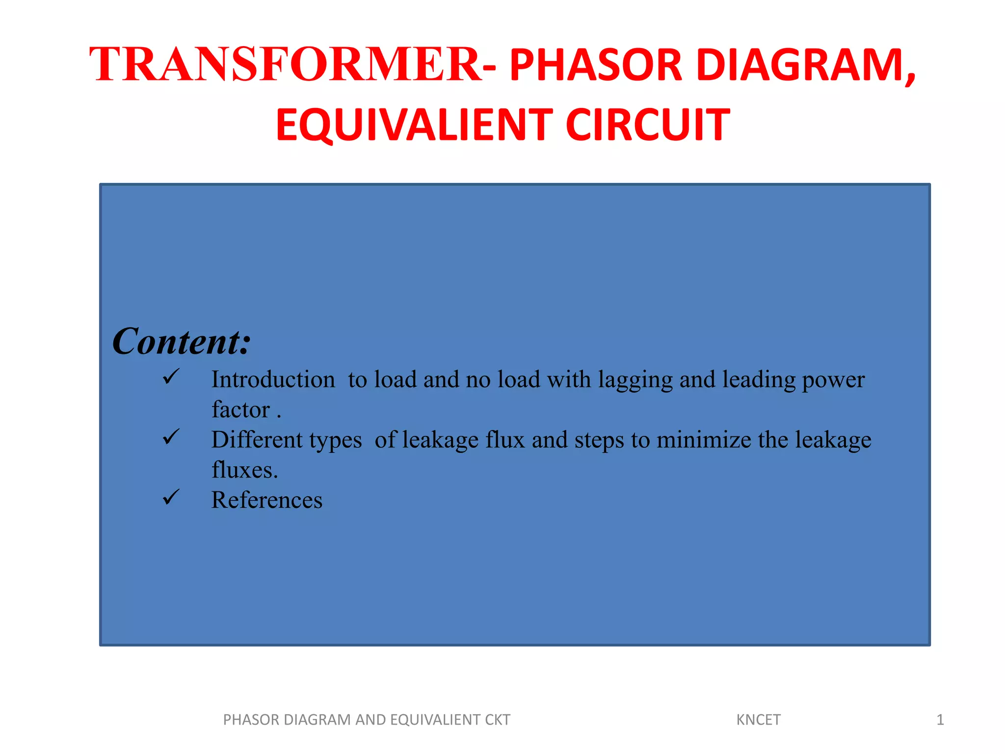
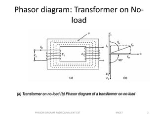
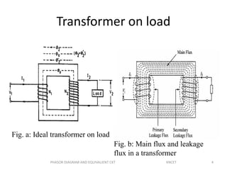
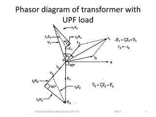
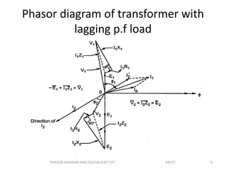
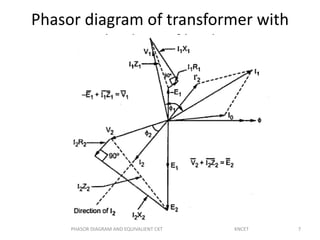
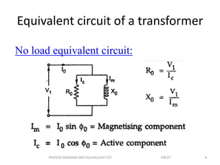
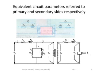
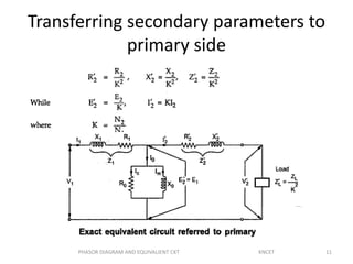
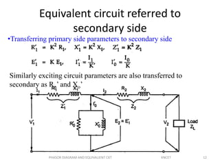
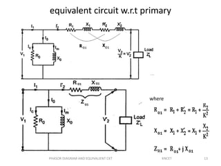
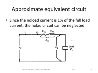
TRANSFORMER- PHASOR DIAGRAM,
EQUIVALIENT CIRCUIT
PHASOR DIAGRAM AND EQUIVALIENT CKT KNCET 1
Content:
 Introduction to load and no load with lagging and leading power
factor .
 Different types of leakage flux and steps to minimize the leakage
fluxes.
 References
2
Phasor diagram: Transformer on No-
load
PHASOR DIAGRAM AND EQUIVALIENT CKT KNCET
Transformer on load assuming no
voltage drop in the winding
Fig shows the Phasor diagram of a transformer
on load by assuming
1. No voltage drop in the winding
2. Equal no. of primary and secondary turns
3PHASOR DIAGRAM AND EQUIVALIENT CKT KNCET
Transformer on load
Fig. a: Ideal transformer on load
Fig. b: Main flux and leakage
flux in a transformer
4PHASOR DIAGRAM AND EQUIVALIENT CKT KNCET
Phasor diagram of transformer with
UPF load
5PHASOR DIAGRAM AND EQUIVALIENT CKT KNCET
Phasor diagram of transformer with
lagging p.f load
6PHASOR DIAGRAM AND EQUIVALIENT CKT KNCET
Phasor diagram of transformer with
leading p.f load
7PHASOR DIAGRAM AND EQUIVALIENT CKT KNCET
Equivalent circuit of a transformer
No load equivalent circuit:
8PHASOR DIAGRAM AND EQUIVALIENT CKT KNCET
Equivalent circuit parameters referred to
primary and secondary sides respectively
9PHASOR DIAGRAM AND EQUIVALIENT CKT KNCET
Contd.,
• The effect of circuit parameters shouldn’t be changed while
transferring the parameters from one side to another side
• It can be proved that a resistance of R2 in sec. is equivalent
to R2/k2 will be denoted as R2’(ie. Equivalent sec. resistance
w.r.t primary) which would have caused the same loss as R2
in secondary,
2
2
2
2
1
2'
2
2
2
2
'
2
2
1
k
R
R









R
I
I
RIRI
10PHASOR DIAGRAM AND EQUIVALIENT CKT KNCET
Transferring secondary parameters to
primary side
11PHASOR DIAGRAM AND EQUIVALIENT CKT KNCET
Equivalent circuit referred to
secondary side
•Transferring primary side parameters to secondary side
Similarly exciting circuit parameters are also transferred to
secondary as Ro’ and Xo’
12PHASOR DIAGRAM AND EQUIVALIENT CKT KNCET
equivalent circuit w.r.t primary
where
13PHASOR DIAGRAM AND EQUIVALIENT CKT KNCET
Approximate equivalent circuit
• Since the noload current is 1% of the full load
current, the nolad circuit can be neglected
14PHASOR DIAGRAM AND EQUIVALIENT CKT KNCET
15PHASOR DIAGRAM AND EQUIVALIENT CKT KNCET
Conclusion:
• Phasor diagram for different load condition is explained in detail with
suitable diagrams.
• Equivalent circuit also drawn with primary and secondary parameters.
References:
1.P. C. Sen., ‘Principles of Electrical Machines and Power Electronics’, John
Wiley & Sons, 1997.
2.P.S. Bimbhra, ‘Electrical Machinery’, Khanna Publishers, 2003.
3.S.Sarma & K.Pathak “Electric Machines”, Cengage Learning India (P) Ltd.,
Delhi, 2011.
4.U.A.Bakshi&M.N.Bakshi “Electric Machines-I”,Technical
publications,2015.
5.Other Web Sources

Phasor diagram

  • 1.
    TRANSFORMER- PHASOR DIAGRAM, EQUIVALIENTCIRCUIT PHASOR DIAGRAM AND EQUIVALIENT CKT KNCET 1 Content:  Introduction to load and no load with lagging and leading power factor .  Different types of leakage flux and steps to minimize the leakage fluxes.  References
  • 2.
    2 Phasor diagram: Transformeron No- load PHASOR DIAGRAM AND EQUIVALIENT CKT KNCET
  • 3.
    Transformer on loadassuming no voltage drop in the winding Fig shows the Phasor diagram of a transformer on load by assuming 1. No voltage drop in the winding 2. Equal no. of primary and secondary turns 3PHASOR DIAGRAM AND EQUIVALIENT CKT KNCET
  • 4.
    Transformer on load Fig.a: Ideal transformer on load Fig. b: Main flux and leakage flux in a transformer 4PHASOR DIAGRAM AND EQUIVALIENT CKT KNCET
  • 5.
    Phasor diagram oftransformer with UPF load 5PHASOR DIAGRAM AND EQUIVALIENT CKT KNCET
  • 6.
    Phasor diagram oftransformer with lagging p.f load 6PHASOR DIAGRAM AND EQUIVALIENT CKT KNCET
  • 7.
    Phasor diagram oftransformer with leading p.f load 7PHASOR DIAGRAM AND EQUIVALIENT CKT KNCET
  • 8.
    Equivalent circuit ofa transformer No load equivalent circuit: 8PHASOR DIAGRAM AND EQUIVALIENT CKT KNCET
  • 9.
    Equivalent circuit parametersreferred to primary and secondary sides respectively 9PHASOR DIAGRAM AND EQUIVALIENT CKT KNCET
  • 10.
    Contd., • The effectof circuit parameters shouldn’t be changed while transferring the parameters from one side to another side • It can be proved that a resistance of R2 in sec. is equivalent to R2/k2 will be denoted as R2’(ie. Equivalent sec. resistance w.r.t primary) which would have caused the same loss as R2 in secondary, 2 2 2 2 1 2' 2 2 2 2 ' 2 2 1 k R R          R I I RIRI 10PHASOR DIAGRAM AND EQUIVALIENT CKT KNCET
  • 11.
    Transferring secondary parametersto primary side 11PHASOR DIAGRAM AND EQUIVALIENT CKT KNCET
  • 12.
    Equivalent circuit referredto secondary side •Transferring primary side parameters to secondary side Similarly exciting circuit parameters are also transferred to secondary as Ro’ and Xo’ 12PHASOR DIAGRAM AND EQUIVALIENT CKT KNCET
  • 13.
    equivalent circuit w.r.tprimary where 13PHASOR DIAGRAM AND EQUIVALIENT CKT KNCET
  • 14.
    Approximate equivalent circuit •Since the noload current is 1% of the full load current, the nolad circuit can be neglected 14PHASOR DIAGRAM AND EQUIVALIENT CKT KNCET
  • 15.
    15PHASOR DIAGRAM ANDEQUIVALIENT CKT KNCET Conclusion: • Phasor diagram for different load condition is explained in detail with suitable diagrams. • Equivalent circuit also drawn with primary and secondary parameters. References: 1.P. C. Sen., ‘Principles of Electrical Machines and Power Electronics’, John Wiley & Sons, 1997. 2.P.S. Bimbhra, ‘Electrical Machinery’, Khanna Publishers, 2003. 3.S.Sarma & K.Pathak “Electric Machines”, Cengage Learning India (P) Ltd., Delhi, 2011. 4.U.A.Bakshi&M.N.Bakshi “Electric Machines-I”,Technical publications,2015. 5.Other Web Sources