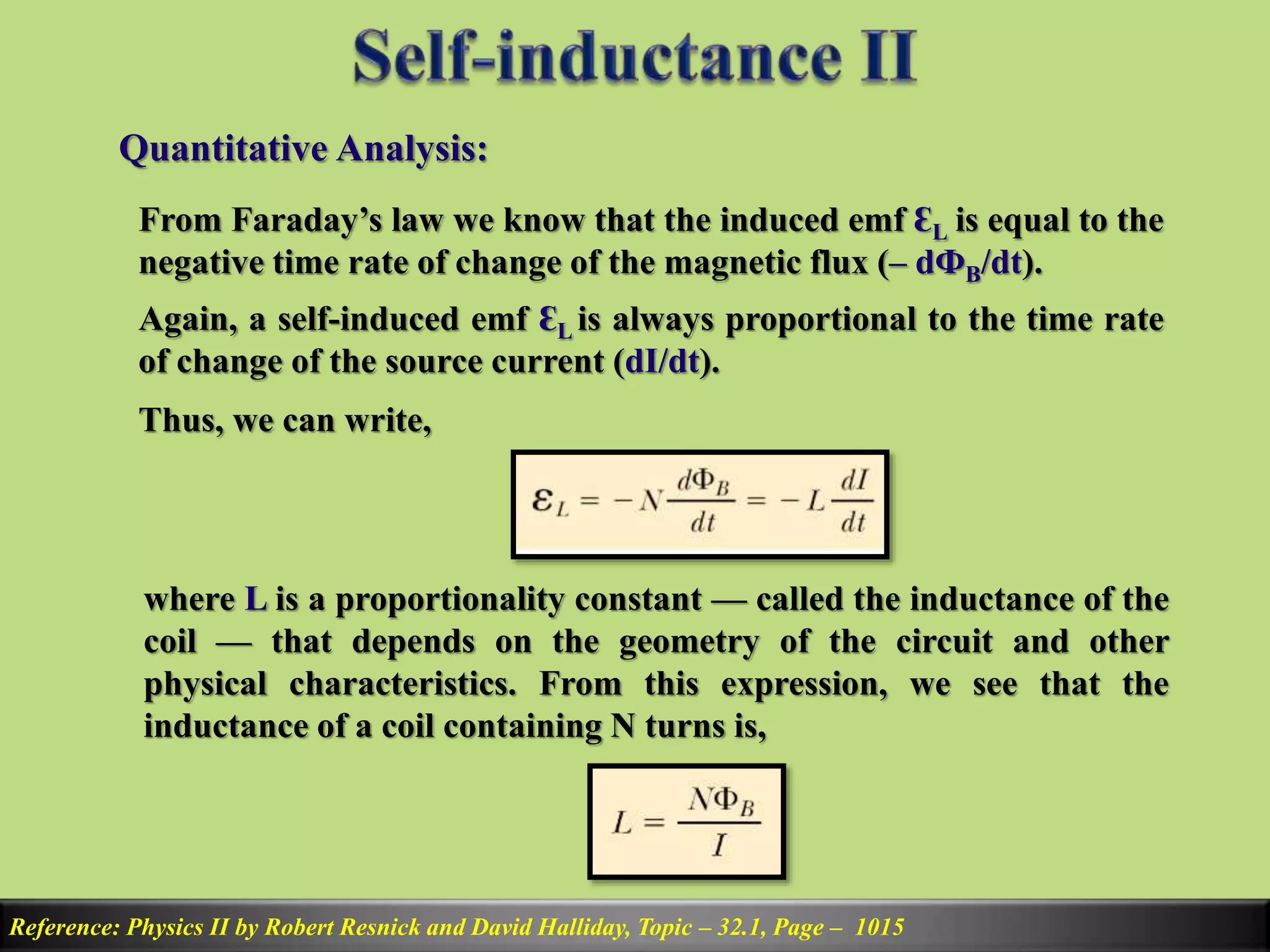
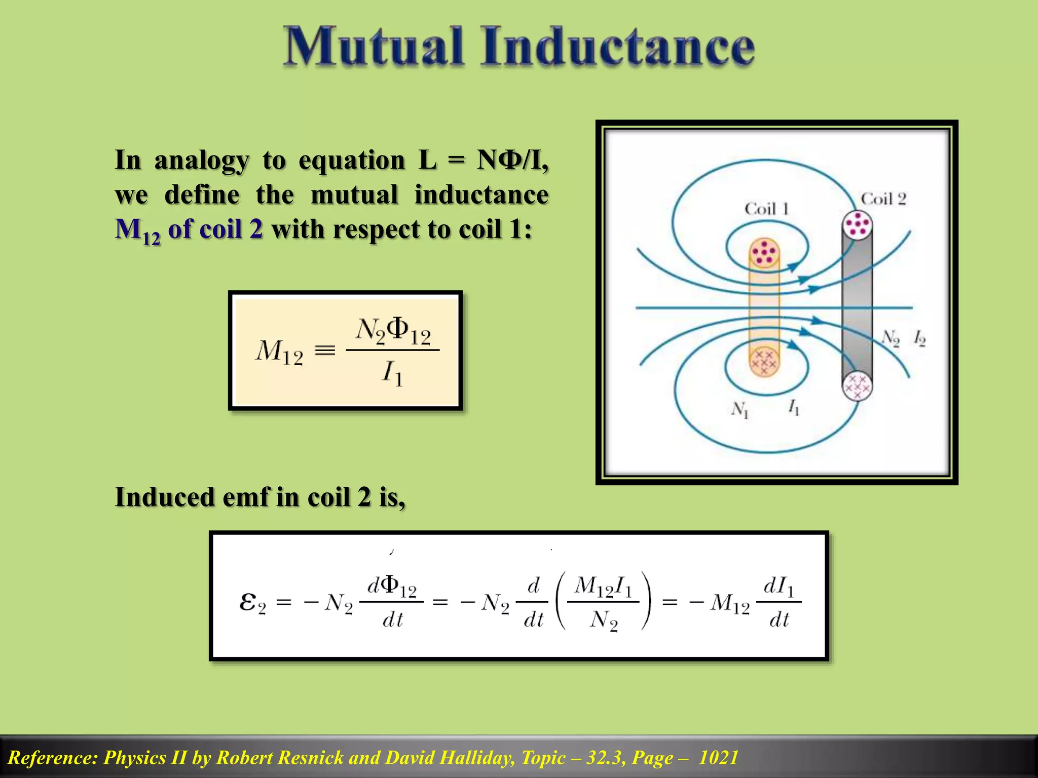
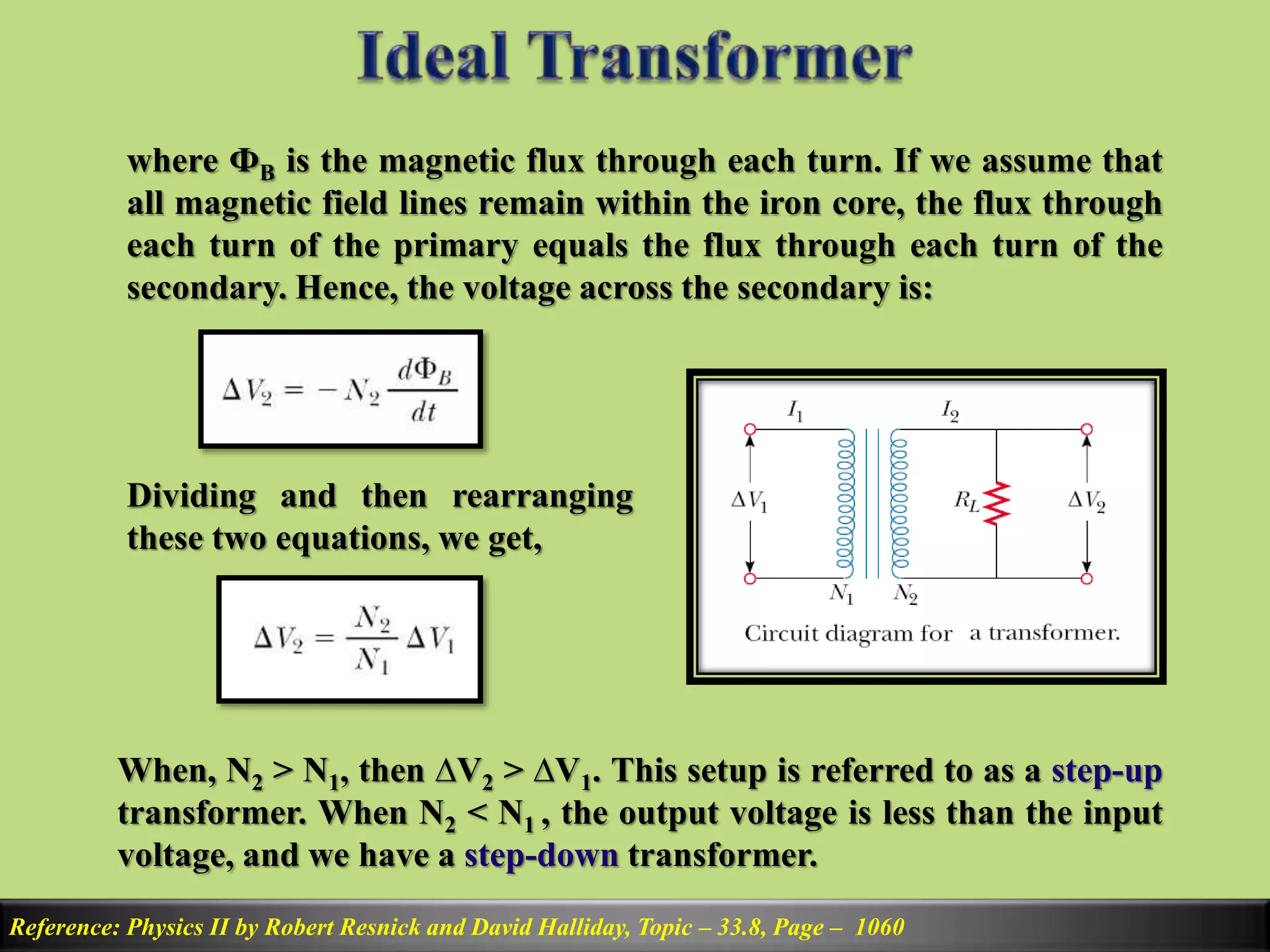
SlideShare a Scribd company logo
1 of 22
Prepared by
Md. Amirul Islam
Lecturer
Department of Applied Physics & Electronics
Bangabandhu Sheikh Mujibur Rahman Science &
Technology University, Gopalganj – 8100
Self Induction and Back emf:
Reference: Physics II by Robert Resnick and David Halliday, Topic – 32.1, Page – 1015
Consider the circuit consisting of a
switch, a resistor, and a source of
emf, as shown in figure. When the
switch is thrown to its closed
position, the source current does
not immediately jump from zero to
its maximum value Ԑ/R. Faraday’s
law of electromagnetic induction
can be used to describe this effect
as follows: As the source current
increases with time, the magnetic flux through the circuit loop due to this
current also increases with time. This increasing flux creates an induced
emf in the circuit. The direction of the induced emf is such that it would
cause an induced current in the loop, which would establish a magnetic
field that would oppose the change in the source magnetic field.
Reference: Physics II by Robert Resnick and David Halliday, Topic – 32.1, Page – 1015
Thus, the direction of the induced
emf is opposite the direction of the
source emf; this results in a gradual
rather than instantaneous increase
in the source current to its final
equilibrium value. This effect is
called self-induction because the
changing flux through the circuit
and the resultant induced emf arise from the circuit itself. The emf ԐL
set up in this case is called a self-induced emf. It is also often called a
back emf.
Inductor or Solenoid:
Reference: Physics II by Robert Resnick and David Halliday, Topic – 32.1, Page – 1015
Consider a coil wound on a cylindrical iron core as shown in figure.
(a) A current in the coil produces a magnetic field directed to the left (Screw
rule) (b) If the current increases, the increasing magnetic flux creates an
induced emf having the polarity shown by the dashed battery (Lenz’s Law) (c)
The polarity of the induced emf reverses if the current decreases.
Quantitative Analysis:
Reference: Physics II by Robert Resnick and David Halliday, Topic – 32.1, Page – 1015
From Faraday’s law we know that the induced emf ԐL is equal to the
negative time rate of change of the magnetic flux (– dФB/dt).
Again, a self-induced emf ԐL is always proportional to the time rate
of change of the source current (dI/dt).
Thus, we can write,
where L is a proportionality constant — called the inductance of the
coil — that depends on the geometry of the circuit and other
physical characteristics. From this expression, we see that the
inductance of a coil containing N turns is,
Unit of Inductance:
Reference: Physics II by Robert Resnick and David Halliday, Topic – 32.1, Page – 1015
From the equation of induced emf, we can write that,
Thus the SI unit of inductance is Henry and can be written as,
Reference: Physics II by Robert Resnick and David Halliday, Topic – 32.3, Page – 1021
Because the emf induced in an inductor prevents a battery from
establishing an instantaneous current, the battery must do work
against the inductor to create a current. Part of the energy supplied
by the battery appears as internal energy in the resistor, while the
remaining energy is stored in the magnetic field of the inductor.
Applying KVL, we get,
IԐ is the energy supplied from the source, I2R is the energy
delivered to the resistor and thus, LI(dI/dt) is the energy stored in
the inductor.
Reference: Physics II by Robert Resnick and David Halliday, Topic – 32.3, Page – 1021
If we let U denote the energy stored in the inductor at any time,
then we can write the rate dU/dt at which energy is stored as,
To find the total energy stored in the inductor, we can rewrite this
expression as dU = LIdI and integrate over the limit 0 to I:
This is the equation of energy stored in an inductor.
Reference: Physics II by Robert Resnick and David Halliday, Topic – 32.3, Page – 1021
Very often, the magnetic flux through the area enclosed by a circuit
varies with time because of time-varying currents in nearby circuits.
This condition induces an emf through a process known as mutual
induction, so called because it depends on the interaction of two
circuits.
Consider the two closely wound
coils of wire in cross-sectional view
in figure. The current I1 in coil 1,
which has N1 turns, creates
magnetic field lines, some of which
pass through coil 2, which has N2
turns. The magnetic flux caused by
the current in coil 1 and passing
through coil 2 is represented by
Ф12.
Reference: Physics II by Robert Resnick and David Halliday, Topic – 32.3, Page – 1021
In analogy to equation L = NФ/I,
we define the mutual inductance
M12 of coil 2 with respect to coil 1:
Induced emf in coil 2 is,
Reference: Physics II by Robert Resnick and David Halliday, Topic – 32.3, Page – 1021
In the preceding discussion, we assumed that the source current is in
coil 1. We can also imagine a source current I2 in coil 2. The
preceding discussion can be repeated to show that there is a mutual
inductance M21 . If the current I2 varies with time, the emf induced
by coil 2 in coil 1 is,
It can be experimentally shown that,
M12 = M21 = M and thus,
The unit of mutual inductance is also Henry.
Reference: Physics II by Robert Resnick and David Halliday, Topic – 33.8, Page – 1060
When electric power is transmitted over great distances, it is
economical to use a high voltage and a low current to minimize the
I2R loss in the transmission lines. Consequently, 33,000V lines are
common. At the receiving end of such lines, the consumer requires
power at a low voltage. Therefore, a device is required that can
change the alternating voltage and current without causing
appreciable changes in the power delivered. The ac transformer is
that device.
Construction:
The ac transformer consists of two
coils of wire wound around a core of
iron, as illustrated in figure. The coil
on the left, which is connected to the
input alternating voltage source and
has N1 turns, is called the primary
winding (or the primary).
Reference: Physics II by Robert Resnick and David Halliday, Topic – 33.8, Page – 1060
The coil on the right, consisting of N2 turns and connected to a load
resistor R, is called the secondary winding (or the secondary). The
purpose of the iron core is to increase the magnetic flux through the
coil and to provide a medium in which nearly all the flux through
one coil passes through the other coil. Eddy current losses are
reduced by using a laminated core. Iron is used as the core material
because it is a soft ferromagnetic substance and hence reduces
hysteresis losses. Although practical transformer have some power
loss due to the resistance of the coil wire, as we assumed an ideal
transformer, so energy losses in the windings and core are zero.
Working Principle:
According to Faraday’s law the voltage
∆V1 across the primary is,
Reference: Physics II by Robert Resnick and David Halliday, Topic – 33.8, Page – 1060
where ФB is the magnetic flux through each turn. If we assume that
all magnetic field lines remain within the iron core, the flux through
each turn of the primary equals the flux through each turn of the
secondary. Hence, the voltage across the secondary is:
Dividing and then rearranging
these two equations, we get,
When, N2 > N1, then ∆V2 > ∆V1. This setup is referred to as a step-up
transformer. When N2 < N1 , the output voltage is less than the input
voltage, and we have a step-down transformer.
Reference: Physics II by Robert Resnick and David Halliday, Topic – 33.8, Page – 1060
For an ideal transformer, there is no power loss on primary or
secondary winding. Thus,
When a resistive load RL is
connected to the secondary, then
current I2 on the secondary will be,
Furthermore, the current in the primary is,
Where,
Reference: Physics II by Robert Resnick and David Halliday, Topic – 33.8, Page – 1060
The above equation relates to the input resistance to the output
resistance. Req is the equivalent resistance of the load resistance
when viewed from the primary side. From this analysis we see that a
transformer may be used to match resistances (impedance matching)
between the primary circuit and the load. In this manner, maximum
power transfer can be achieved between a given power source and
the load resistance.
How induction and back emf work in circuits and transformers

More Related Content

What's hot

self inductance , mutual inductance and coeffecient of coupling
self inductance , mutual inductance and coeffecient of couplingself inductance , mutual inductance and coeffecient of coupling
self inductance , mutual inductance and coeffecient of couplingsaahil kshatriya
 
Magnetic Effects Of Current Class 12 Part-2
Magnetic Effects Of Current Class 12 Part-2Magnetic Effects Of Current Class 12 Part-2
Magnetic Effects Of Current Class 12 Part-2Self-employed
 
Physics Investigatory Project
Physics Investigatory ProjectPhysics Investigatory Project
Physics Investigatory ProjectNishant Jha
 
Ac fundamentals 3 power in ac circuits
Ac fundamentals 3  power in ac circuitsAc fundamentals 3  power in ac circuits
Ac fundamentals 3 power in ac circuitsUniversity of Potsdam
 
Physics project chirag
Physics project chiragPhysics project chirag
Physics project chiragChirag Patel
 
Magnetic Effects Of Current Class 12 Part-1
Magnetic Effects Of Current Class 12 Part-1Magnetic Effects Of Current Class 12 Part-1
Magnetic Effects Of Current Class 12 Part-1Self-employed
 
electromagnetic induction ( part 1 )
electromagnetic induction ( part 1 )electromagnetic induction ( part 1 )
electromagnetic induction ( part 1 )Priyanka Jakhar
 
Physics investigatory project by pinaki bandyopadhyay
Physics investigatory project by pinaki bandyopadhyayPhysics investigatory project by pinaki bandyopadhyay
Physics investigatory project by pinaki bandyopadhyayPinaki Bandyopadhyay
 
Class 12th physics current electricity ppt
Class 12th physics current electricity ppt Class 12th physics current electricity ppt
Class 12th physics current electricity ppt Arpit Meena
 
Alternating current circuits
Alternating current circuitsAlternating current circuits
Alternating current circuitscse1014
 
Pn junction diode class 12 investegatory project
Pn junction diode class 12 investegatory projectPn junction diode class 12 investegatory project
Pn junction diode class 12 investegatory projectabhijeet singh
 
L14 self and mutual inductance
L14   self and mutual inductanceL14   self and mutual inductance
L14 self and mutual inductanceSatyakam
 
Current Electricity Class 12 Part-3
Current Electricity Class 12 Part-3Current Electricity Class 12 Part-3
Current Electricity Class 12 Part-3Self-employed
 
Nuclei And Atoms Class 12
Nuclei And Atoms Class 12Nuclei And Atoms Class 12
Nuclei And Atoms Class 12Self-employed
 
INVESTIGATORY PROJECT ON SEMICONDUCTOR by shivam jhade
INVESTIGATORY PROJECT ON SEMICONDUCTOR by shivam jhade INVESTIGATORY PROJECT ON SEMICONDUCTOR by shivam jhade
INVESTIGATORY PROJECT ON SEMICONDUCTOR by shivam jhade bhopal
 

What's hot (20)

self inductance , mutual inductance and coeffecient of coupling
self inductance , mutual inductance and coeffecient of couplingself inductance , mutual inductance and coeffecient of coupling
self inductance , mutual inductance and coeffecient of coupling
 
Magnetic Effects Of Current Class 12 Part-2
Magnetic Effects Of Current Class 12 Part-2Magnetic Effects Of Current Class 12 Part-2
Magnetic Effects Of Current Class 12 Part-2
 
Physics Investigatory Project
Physics Investigatory ProjectPhysics Investigatory Project
Physics Investigatory Project
 
Ac fundamentals 3 power in ac circuits
Ac fundamentals 3  power in ac circuitsAc fundamentals 3  power in ac circuits
Ac fundamentals 3 power in ac circuits
 
Physics project chirag
Physics project chiragPhysics project chirag
Physics project chirag
 
Magnetic Effects Of Current Class 12 Part-1
Magnetic Effects Of Current Class 12 Part-1Magnetic Effects Of Current Class 12 Part-1
Magnetic Effects Of Current Class 12 Part-1
 
electromagnetic induction ( part 1 )
electromagnetic induction ( part 1 )electromagnetic induction ( part 1 )
electromagnetic induction ( part 1 )
 
Physics investigatory project by pinaki bandyopadhyay
Physics investigatory project by pinaki bandyopadhyayPhysics investigatory project by pinaki bandyopadhyay
Physics investigatory project by pinaki bandyopadhyay
 
Class 12th physics current electricity ppt
Class 12th physics current electricity ppt Class 12th physics current electricity ppt
Class 12th physics current electricity ppt
 
Alternating current circuits
Alternating current circuitsAlternating current circuits
Alternating current circuits
 
Pn junction diode class 12 investegatory project
Pn junction diode class 12 investegatory projectPn junction diode class 12 investegatory project
Pn junction diode class 12 investegatory project
 
Physics investigatory project
Physics investigatory projectPhysics investigatory project
Physics investigatory project
 
Transformers
TransformersTransformers
Transformers
 
L14 self and mutual inductance
L14   self and mutual inductanceL14   self and mutual inductance
L14 self and mutual inductance
 
Sanjay
SanjaySanjay
Sanjay
 
Current Electricity Class 12 Part-3
Current Electricity Class 12 Part-3Current Electricity Class 12 Part-3
Current Electricity Class 12 Part-3
 
Nuclei And Atoms Class 12
Nuclei And Atoms Class 12Nuclei And Atoms Class 12
Nuclei And Atoms Class 12
 
Magnetism
MagnetismMagnetism
Magnetism
 
INVESTIGATORY PROJECT ON SEMICONDUCTOR by shivam jhade
INVESTIGATORY PROJECT ON SEMICONDUCTOR by shivam jhade INVESTIGATORY PROJECT ON SEMICONDUCTOR by shivam jhade
INVESTIGATORY PROJECT ON SEMICONDUCTOR by shivam jhade
 
Lenzs law presentation
Lenzs law presentationLenzs law presentation
Lenzs law presentation
 

Similar to How induction and back emf work in circuits and transformers

Similar to How induction and back emf work in circuits and transformers (20)

6 inductance
6 inductance6 inductance
6 inductance
 
chapter32.ppt
chapter32.pptchapter32.ppt
chapter32.ppt
 
Arpita nandi
Arpita nandiArpita nandi
Arpita nandi
 
Magnetism 2
Magnetism 2Magnetism 2
Magnetism 2
 
Investigatory Project Physics.pdf
Investigatory Project Physics.pdfInvestigatory Project Physics.pdf
Investigatory Project Physics.pdf
 
Electromagnetic induction
Electromagnetic inductionElectromagnetic induction
Electromagnetic induction
 
Electricity and magnetism
Electricity and magnetismElectricity and magnetism
Electricity and magnetism
 
CIRCUIT AND NETWORK THEORY
CIRCUIT AND NETWORK THEORYCIRCUIT AND NETWORK THEORY
CIRCUIT AND NETWORK THEORY
 
Ekeeda - First Year Enginering - Basic Electrical Engineering
Ekeeda - First Year Enginering - Basic Electrical EngineeringEkeeda - First Year Enginering - Basic Electrical Engineering
Ekeeda - First Year Enginering - Basic Electrical Engineering
 
Ekeeda backlinks
Ekeeda backlinksEkeeda backlinks
Ekeeda backlinks
 
Analog circuits-lab-possible-viva-questions
Analog circuits-lab-possible-viva-questionsAnalog circuits-lab-possible-viva-questions
Analog circuits-lab-possible-viva-questions
 
Eg1108 transformers
Eg1108 transformersEg1108 transformers
Eg1108 transformers
 
Nptel.ac.in courses 108106071_pdfs_1_4
Nptel.ac.in courses 108106071_pdfs_1_4Nptel.ac.in courses 108106071_pdfs_1_4
Nptel.ac.in courses 108106071_pdfs_1_4
 
Physics_Investigatory_Project_Abhishek_c (1).pdf
Physics_Investigatory_Project_Abhishek_c (1).pdfPhysics_Investigatory_Project_Abhishek_c (1).pdf
Physics_Investigatory_Project_Abhishek_c (1).pdf
 
Physics project abhishek
Physics project abhishekPhysics project abhishek
Physics project abhishek
 
Unit 1.doc
Unit 1.docUnit 1.doc
Unit 1.doc
 
PEE-102A_L-4
PEE-102A_L-4PEE-102A_L-4
PEE-102A_L-4
 
PHYSICS II - Supplemental Guide
PHYSICS II - Supplemental GuidePHYSICS II - Supplemental Guide
PHYSICS II - Supplemental Guide
 
Current electricity
Current electricityCurrent electricity
Current electricity
 
Electromagnetic induction and transformer
Electromagnetic induction and transformer Electromagnetic induction and transformer
Electromagnetic induction and transformer
 

More from Bangabandhu Sheikh Mujibur Rahman Science and Technology University

More from Bangabandhu Sheikh Mujibur Rahman Science and Technology University (20)

Antenna (2)
Antenna (2)Antenna (2)
Antenna (2)
 
Voltage suppler..
Voltage suppler..Voltage suppler..
Voltage suppler..
 
Number system
Number systemNumber system
Number system
 
Chapter 15
Chapter 15Chapter 15
Chapter 15
 
Chap 13(dynamic memory allocation)
Chap 13(dynamic memory allocation)Chap 13(dynamic memory allocation)
Chap 13(dynamic memory allocation)
 
Chap 12(files)
Chap 12(files)Chap 12(files)
Chap 12(files)
 
Chap 11(pointers)
Chap 11(pointers)Chap 11(pointers)
Chap 11(pointers)
 
Chap 10(structure and unions)
Chap 10(structure and unions)Chap 10(structure and unions)
Chap 10(structure and unions)
 
Chap 9(functions)
Chap 9(functions)Chap 9(functions)
Chap 9(functions)
 
Chap 8(strings)
Chap 8(strings)Chap 8(strings)
Chap 8(strings)
 
Chap 7(array)
Chap 7(array)Chap 7(array)
Chap 7(array)
 
Chap 6(decision making-looping)
Chap 6(decision making-looping)Chap 6(decision making-looping)
Chap 6(decision making-looping)
 
Chap 5(decision making-branching)
Chap 5(decision making-branching)Chap 5(decision making-branching)
Chap 5(decision making-branching)
 
Chap 3(operator expression)
Chap 3(operator expression)Chap 3(operator expression)
Chap 3(operator expression)
 
Chap 2(const var-datatype)
Chap 2(const var-datatype)Chap 2(const var-datatype)
Chap 2(const var-datatype)
 
Computer hardware ppt1
Computer hardware ppt1Computer hardware ppt1
Computer hardware ppt1
 
# Operating system
# Operating system# Operating system
# Operating system
 
2. sinusoidal waves
2. sinusoidal waves2. sinusoidal waves
2. sinusoidal waves
 
Magnetism 1
Magnetism 1Magnetism 1
Magnetism 1
 
1. rc rl-rlc
1. rc rl-rlc1. rc rl-rlc
1. rc rl-rlc
 

Recently uploaded

URLs and Routing in the Odoo 17 Website App
URLs and Routing in the Odoo 17 Website AppURLs and Routing in the Odoo 17 Website App
URLs and Routing in the Odoo 17 Website AppCeline George
 
Concept of Vouching. B.Com(Hons) /B.Compdf
Concept of Vouching. B.Com(Hons) /B.CompdfConcept of Vouching. B.Com(Hons) /B.Compdf
Concept of Vouching. B.Com(Hons) /B.CompdfUmakantAnnand
 
Presentation by Andreas Schleicher Tackling the School Absenteeism Crisis 30 ...
Presentation by Andreas Schleicher Tackling the School Absenteeism Crisis 30 ...Presentation by Andreas Schleicher Tackling the School Absenteeism Crisis 30 ...
Presentation by Andreas Schleicher Tackling the School Absenteeism Crisis 30 ...EduSkills OECD
 
The Most Excellent Way | 1 Corinthians 13
The Most Excellent Way | 1 Corinthians 13The Most Excellent Way | 1 Corinthians 13
The Most Excellent Way | 1 Corinthians 13Steve Thomason
 
Micromeritics - Fundamental and Derived Properties of Powders
Micromeritics - Fundamental and Derived Properties of PowdersMicromeritics - Fundamental and Derived Properties of Powders
Micromeritics - Fundamental and Derived Properties of PowdersChitralekhaTherkar
 
Presiding Officer Training module 2024 lok sabha elections
Presiding Officer Training module 2024 lok sabha electionsPresiding Officer Training module 2024 lok sabha elections
Presiding Officer Training module 2024 lok sabha electionsanshu789521
 
APM Welcome, APM North West Network Conference, Synergies Across Sectors
APM Welcome, APM North West Network Conference, Synergies Across SectorsAPM Welcome, APM North West Network Conference, Synergies Across Sectors
APM Welcome, APM North West Network Conference, Synergies Across SectorsAssociation for Project Management
 
MENTAL STATUS EXAMINATION format.docx
MENTAL     STATUS EXAMINATION format.docxMENTAL     STATUS EXAMINATION format.docx
MENTAL STATUS EXAMINATION format.docxPoojaSen20
 
CARE OF CHILD IN INCUBATOR..........pptx
CARE OF CHILD IN INCUBATOR..........pptxCARE OF CHILD IN INCUBATOR..........pptx
CARE OF CHILD IN INCUBATOR..........pptxGaneshChakor2
 
Alper Gobel In Media Res Media Component
Alper Gobel In Media Res Media ComponentAlper Gobel In Media Res Media Component
Alper Gobel In Media Res Media ComponentInMediaRes1
 
Measures of Central Tendency: Mean, Median and Mode
Measures of Central Tendency: Mean, Median and ModeMeasures of Central Tendency: Mean, Median and Mode
Measures of Central Tendency: Mean, Median and ModeThiyagu K
 
SOCIAL AND HISTORICAL CONTEXT - LFTVD.pptx
SOCIAL AND HISTORICAL CONTEXT - LFTVD.pptxSOCIAL AND HISTORICAL CONTEXT - LFTVD.pptx
SOCIAL AND HISTORICAL CONTEXT - LFTVD.pptxiammrhaywood
 
Employee wellbeing at the workplace.pptx
Employee wellbeing at the workplace.pptxEmployee wellbeing at the workplace.pptx
Employee wellbeing at the workplace.pptxNirmalaLoungPoorunde1
 
mini mental status format.docx
mini    mental       status     format.docxmini    mental       status     format.docx
mini mental status format.docxPoojaSen20
 
Incoming and Outgoing Shipments in 1 STEP Using Odoo 17
Incoming and Outgoing Shipments in 1 STEP Using Odoo 17Incoming and Outgoing Shipments in 1 STEP Using Odoo 17
Incoming and Outgoing Shipments in 1 STEP Using Odoo 17Celine George
 
Industrial Policy - 1948, 1956, 1973, 1977, 1980, 1991
Industrial Policy - 1948, 1956, 1973, 1977, 1980, 1991Industrial Policy - 1948, 1956, 1973, 1977, 1980, 1991
Industrial Policy - 1948, 1956, 1973, 1977, 1980, 1991RKavithamani
 
Q4-W6-Restating Informational Text Grade 3
Q4-W6-Restating Informational Text Grade 3Q4-W6-Restating Informational Text Grade 3
Q4-W6-Restating Informational Text Grade 3JemimahLaneBuaron
 
Kisan Call Centre - To harness potential of ICT in Agriculture by answer farm...
Kisan Call Centre - To harness potential of ICT in Agriculture by answer farm...Kisan Call Centre - To harness potential of ICT in Agriculture by answer farm...
Kisan Call Centre - To harness potential of ICT in Agriculture by answer farm...Krashi Coaching
 

Recently uploaded (20)

URLs and Routing in the Odoo 17 Website App
URLs and Routing in the Odoo 17 Website AppURLs and Routing in the Odoo 17 Website App
URLs and Routing in the Odoo 17 Website App
 
Concept of Vouching. B.Com(Hons) /B.Compdf
Concept of Vouching. B.Com(Hons) /B.CompdfConcept of Vouching. B.Com(Hons) /B.Compdf
Concept of Vouching. B.Com(Hons) /B.Compdf
 
Presentation by Andreas Schleicher Tackling the School Absenteeism Crisis 30 ...
Presentation by Andreas Schleicher Tackling the School Absenteeism Crisis 30 ...Presentation by Andreas Schleicher Tackling the School Absenteeism Crisis 30 ...
Presentation by Andreas Schleicher Tackling the School Absenteeism Crisis 30 ...
 
The Most Excellent Way | 1 Corinthians 13
The Most Excellent Way | 1 Corinthians 13The Most Excellent Way | 1 Corinthians 13
The Most Excellent Way | 1 Corinthians 13
 
Micromeritics - Fundamental and Derived Properties of Powders
Micromeritics - Fundamental and Derived Properties of PowdersMicromeritics - Fundamental and Derived Properties of Powders
Micromeritics - Fundamental and Derived Properties of Powders
 
Presiding Officer Training module 2024 lok sabha elections
Presiding Officer Training module 2024 lok sabha electionsPresiding Officer Training module 2024 lok sabha elections
Presiding Officer Training module 2024 lok sabha elections
 
APM Welcome, APM North West Network Conference, Synergies Across Sectors
APM Welcome, APM North West Network Conference, Synergies Across SectorsAPM Welcome, APM North West Network Conference, Synergies Across Sectors
APM Welcome, APM North West Network Conference, Synergies Across Sectors
 
MENTAL STATUS EXAMINATION format.docx
MENTAL     STATUS EXAMINATION format.docxMENTAL     STATUS EXAMINATION format.docx
MENTAL STATUS EXAMINATION format.docx
 
Código Creativo y Arte de Software | Unidad 1
Código Creativo y Arte de Software | Unidad 1Código Creativo y Arte de Software | Unidad 1
Código Creativo y Arte de Software | Unidad 1
 
CARE OF CHILD IN INCUBATOR..........pptx
CARE OF CHILD IN INCUBATOR..........pptxCARE OF CHILD IN INCUBATOR..........pptx
CARE OF CHILD IN INCUBATOR..........pptx
 
Alper Gobel In Media Res Media Component
Alper Gobel In Media Res Media ComponentAlper Gobel In Media Res Media Component
Alper Gobel In Media Res Media Component
 
Measures of Central Tendency: Mean, Median and Mode
Measures of Central Tendency: Mean, Median and ModeMeasures of Central Tendency: Mean, Median and Mode
Measures of Central Tendency: Mean, Median and Mode
 
SOCIAL AND HISTORICAL CONTEXT - LFTVD.pptx
SOCIAL AND HISTORICAL CONTEXT - LFTVD.pptxSOCIAL AND HISTORICAL CONTEXT - LFTVD.pptx
SOCIAL AND HISTORICAL CONTEXT - LFTVD.pptx
 
Model Call Girl in Tilak Nagar Delhi reach out to us at 🔝9953056974🔝
Model Call Girl in Tilak Nagar Delhi reach out to us at 🔝9953056974🔝Model Call Girl in Tilak Nagar Delhi reach out to us at 🔝9953056974🔝
Model Call Girl in Tilak Nagar Delhi reach out to us at 🔝9953056974🔝
 
Employee wellbeing at the workplace.pptx
Employee wellbeing at the workplace.pptxEmployee wellbeing at the workplace.pptx
Employee wellbeing at the workplace.pptx
 
mini mental status format.docx
mini    mental       status     format.docxmini    mental       status     format.docx
mini mental status format.docx
 
Incoming and Outgoing Shipments in 1 STEP Using Odoo 17
Incoming and Outgoing Shipments in 1 STEP Using Odoo 17Incoming and Outgoing Shipments in 1 STEP Using Odoo 17
Incoming and Outgoing Shipments in 1 STEP Using Odoo 17
 
Industrial Policy - 1948, 1956, 1973, 1977, 1980, 1991
Industrial Policy - 1948, 1956, 1973, 1977, 1980, 1991Industrial Policy - 1948, 1956, 1973, 1977, 1980, 1991
Industrial Policy - 1948, 1956, 1973, 1977, 1980, 1991
 
Q4-W6-Restating Informational Text Grade 3
Q4-W6-Restating Informational Text Grade 3Q4-W6-Restating Informational Text Grade 3
Q4-W6-Restating Informational Text Grade 3
 
Kisan Call Centre - To harness potential of ICT in Agriculture by answer farm...
Kisan Call Centre - To harness potential of ICT in Agriculture by answer farm...Kisan Call Centre - To harness potential of ICT in Agriculture by answer farm...
Kisan Call Centre - To harness potential of ICT in Agriculture by answer farm...
 

How induction and back emf work in circuits and transformers

  • 1. Prepared by Md. Amirul Islam Lecturer Department of Applied Physics & Electronics Bangabandhu Sheikh Mujibur Rahman Science & Technology University, Gopalganj – 8100
  • 2.
  • 3. Self Induction and Back emf: Reference: Physics II by Robert Resnick and David Halliday, Topic – 32.1, Page – 1015 Consider the circuit consisting of a switch, a resistor, and a source of emf, as shown in figure. When the switch is thrown to its closed position, the source current does not immediately jump from zero to its maximum value Ԑ/R. Faraday’s law of electromagnetic induction can be used to describe this effect as follows: As the source current increases with time, the magnetic flux through the circuit loop due to this current also increases with time. This increasing flux creates an induced emf in the circuit. The direction of the induced emf is such that it would cause an induced current in the loop, which would establish a magnetic field that would oppose the change in the source magnetic field.
  • 4. Reference: Physics II by Robert Resnick and David Halliday, Topic – 32.1, Page – 1015 Thus, the direction of the induced emf is opposite the direction of the source emf; this results in a gradual rather than instantaneous increase in the source current to its final equilibrium value. This effect is called self-induction because the changing flux through the circuit and the resultant induced emf arise from the circuit itself. The emf ԐL set up in this case is called a self-induced emf. It is also often called a back emf.
  • 5.
  • 6. Inductor or Solenoid: Reference: Physics II by Robert Resnick and David Halliday, Topic – 32.1, Page – 1015 Consider a coil wound on a cylindrical iron core as shown in figure. (a) A current in the coil produces a magnetic field directed to the left (Screw rule) (b) If the current increases, the increasing magnetic flux creates an induced emf having the polarity shown by the dashed battery (Lenz’s Law) (c) The polarity of the induced emf reverses if the current decreases.
  • 7. Quantitative Analysis: Reference: Physics II by Robert Resnick and David Halliday, Topic – 32.1, Page – 1015 From Faraday’s law we know that the induced emf ԐL is equal to the negative time rate of change of the magnetic flux (– dФB/dt). Again, a self-induced emf ԐL is always proportional to the time rate of change of the source current (dI/dt). Thus, we can write, where L is a proportionality constant — called the inductance of the coil — that depends on the geometry of the circuit and other physical characteristics. From this expression, we see that the inductance of a coil containing N turns is,
  • 8. Unit of Inductance: Reference: Physics II by Robert Resnick and David Halliday, Topic – 32.1, Page – 1015 From the equation of induced emf, we can write that, Thus the SI unit of inductance is Henry and can be written as,
  • 9.
  • 10. Reference: Physics II by Robert Resnick and David Halliday, Topic – 32.3, Page – 1021 Because the emf induced in an inductor prevents a battery from establishing an instantaneous current, the battery must do work against the inductor to create a current. Part of the energy supplied by the battery appears as internal energy in the resistor, while the remaining energy is stored in the magnetic field of the inductor. Applying KVL, we get, IԐ is the energy supplied from the source, I2R is the energy delivered to the resistor and thus, LI(dI/dt) is the energy stored in the inductor.
  • 11. Reference: Physics II by Robert Resnick and David Halliday, Topic – 32.3, Page – 1021 If we let U denote the energy stored in the inductor at any time, then we can write the rate dU/dt at which energy is stored as, To find the total energy stored in the inductor, we can rewrite this expression as dU = LIdI and integrate over the limit 0 to I: This is the equation of energy stored in an inductor.
  • 12.
  • 13. Reference: Physics II by Robert Resnick and David Halliday, Topic – 32.3, Page – 1021 Very often, the magnetic flux through the area enclosed by a circuit varies with time because of time-varying currents in nearby circuits. This condition induces an emf through a process known as mutual induction, so called because it depends on the interaction of two circuits. Consider the two closely wound coils of wire in cross-sectional view in figure. The current I1 in coil 1, which has N1 turns, creates magnetic field lines, some of which pass through coil 2, which has N2 turns. The magnetic flux caused by the current in coil 1 and passing through coil 2 is represented by Ф12.
  • 14. Reference: Physics II by Robert Resnick and David Halliday, Topic – 32.3, Page – 1021 In analogy to equation L = NФ/I, we define the mutual inductance M12 of coil 2 with respect to coil 1: Induced emf in coil 2 is,
  • 15. Reference: Physics II by Robert Resnick and David Halliday, Topic – 32.3, Page – 1021 In the preceding discussion, we assumed that the source current is in coil 1. We can also imagine a source current I2 in coil 2. The preceding discussion can be repeated to show that there is a mutual inductance M21 . If the current I2 varies with time, the emf induced by coil 2 in coil 1 is, It can be experimentally shown that, M12 = M21 = M and thus, The unit of mutual inductance is also Henry.
  • 16.
  • 17. Reference: Physics II by Robert Resnick and David Halliday, Topic – 33.8, Page – 1060 When electric power is transmitted over great distances, it is economical to use a high voltage and a low current to minimize the I2R loss in the transmission lines. Consequently, 33,000V lines are common. At the receiving end of such lines, the consumer requires power at a low voltage. Therefore, a device is required that can change the alternating voltage and current without causing appreciable changes in the power delivered. The ac transformer is that device. Construction: The ac transformer consists of two coils of wire wound around a core of iron, as illustrated in figure. The coil on the left, which is connected to the input alternating voltage source and has N1 turns, is called the primary winding (or the primary).
  • 18. Reference: Physics II by Robert Resnick and David Halliday, Topic – 33.8, Page – 1060 The coil on the right, consisting of N2 turns and connected to a load resistor R, is called the secondary winding (or the secondary). The purpose of the iron core is to increase the magnetic flux through the coil and to provide a medium in which nearly all the flux through one coil passes through the other coil. Eddy current losses are reduced by using a laminated core. Iron is used as the core material because it is a soft ferromagnetic substance and hence reduces hysteresis losses. Although practical transformer have some power loss due to the resistance of the coil wire, as we assumed an ideal transformer, so energy losses in the windings and core are zero. Working Principle: According to Faraday’s law the voltage ∆V1 across the primary is,
  • 19. Reference: Physics II by Robert Resnick and David Halliday, Topic – 33.8, Page – 1060 where ФB is the magnetic flux through each turn. If we assume that all magnetic field lines remain within the iron core, the flux through each turn of the primary equals the flux through each turn of the secondary. Hence, the voltage across the secondary is: Dividing and then rearranging these two equations, we get, When, N2 > N1, then ∆V2 > ∆V1. This setup is referred to as a step-up transformer. When N2 < N1 , the output voltage is less than the input voltage, and we have a step-down transformer.
  • 20. Reference: Physics II by Robert Resnick and David Halliday, Topic – 33.8, Page – 1060 For an ideal transformer, there is no power loss on primary or secondary winding. Thus, When a resistive load RL is connected to the secondary, then current I2 on the secondary will be, Furthermore, the current in the primary is, Where,
  • 21. Reference: Physics II by Robert Resnick and David Halliday, Topic – 33.8, Page – 1060 The above equation relates to the input resistance to the output resistance. Req is the equivalent resistance of the load resistance when viewed from the primary side. From this analysis we see that a transformer may be used to match resistances (impedance matching) between the primary circuit and the load. In this manner, maximum power transfer can be achieved between a given power source and the load resistance.