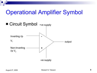
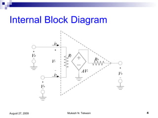
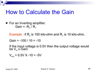
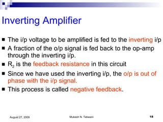
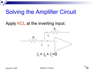
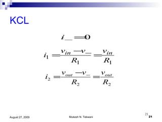
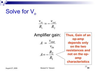
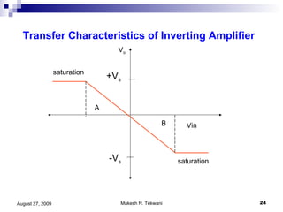
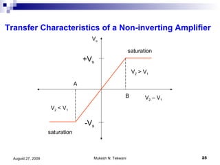
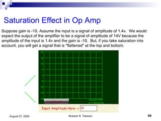
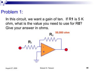
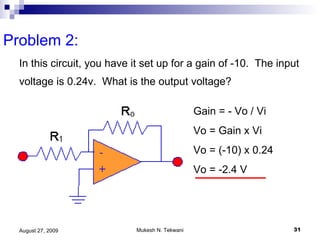
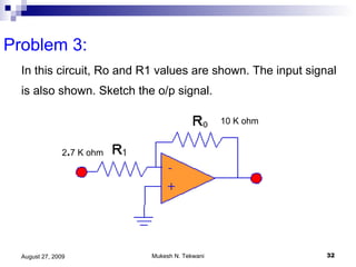
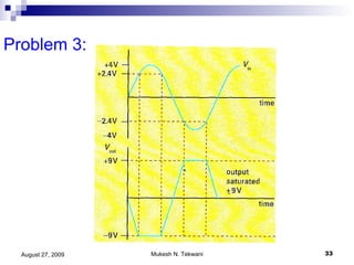
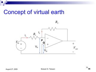
Operational Amplifier    Part 1 Mukesh N Tekwani tekwani@ email.com
Operational Amplifier Originally an op-amp was an electronic circuit that could carry out  mathematical   operations  of addition, subtraction, differentiation and integration. Hence the word “operational” Op-amp is used to  amplify  DC and AC signals.
Operational Amplifier Symbol Circuit Symbol - + +ve supply -ve supply output Inverting i/p V 1 Non-Inverting i/p V 2
Internal Block Diagram
Characteristics of Ideal Op-Amp Infinite   input  impedance (about 2 Mohm) Low output  impedance (about 200 ohm) Very large voltage gain at low frequency Thus, small changes in voltages can be amplified by using an op-amp Infinite bandwidth  (all frequencies are amplified by same factor No slew rate  – no delay between change in i/p and changes in o/p
Op Amp Characteristics Explained Infinite input impedance no current flows into inputs Infinite voltage gain a voltage difference at the two inputs is magnified to a very large extent in practice, voltage gain ~ 200000 means difference between + terminal and    terminal is amplified by 200,000!
Op Amp Characteristics Explained Infinite bandwidth In practice, bandwidth limited to few MHz range slew rate  limited to 0.5–20 V/  s
Op Amp Slew Rate Explained The o/p of an op amp does not change instantaneously. The rate of change of o/p of an op amp is limited (about 0.5 V/    sec) So, if we want to change the o/p voltage from 0 to 10 V, it would take 20   s
Op Amp Slew Rate Explained
Operational Amplifier Without Feedback The op-amp can be regarded as a device which generates an voltage V o  given by: V o  = A (V 2  – V 1 ) A is called as the  gain  of the amplifier. V 1  is the voltage applied at the inverting input,  V 2  is the voltage applied at the non-inverting input,
Variation of Gain with Frequency The value of gain A depends on the frequency of the i/p signal and is very high at low frequencies.  At DC, (f = 0 Hz), gain A is about 10 5 . But the gain decreases with frequency.
Variation of Output voltage with V 1 V o  = A (V 2  – V 1 )  When V 2  = 0, V o  = -AV 1 So, the  output voltage is out of phase with the input voltage  applied to the inverting input. That is why it is called the “ inverting ” input
Variation of Output voltage with V 2 V o  = A (V 2  – V 1 )  When V 1  = 0, V o  = AV 2 So, the  output voltage is in phase with the input voltage  applied to the non-inverting input. That is why it is called the “ non-inverting ” input
Variation of Output with Input Voltages V o  = A (V 2  – V 1 ) If V 2  > V 1 , V o  is positive If V 2  < V 1 , V o  is negative If V 2  = V 1 , V o  is zero
Consequences of Ideal characteristics Infinite input resistance  means the current into the inverting input is zero: i -  = 0 Infinite gain  means the difference between V 1  and V 2  is zero: V 2  – V 1  = 0
The Basic Inverting Amplifier R 2 V in – + + – V out R 1 + – I 1 I 2 Resistor used to control amplification
How to Calculate the Gain   For an Inverting amplifier: Gain = -R 2  / R 1 Example  : if R 2  is 100 kilo-ohm and R 1  is 10 kilo-ohm, Gain = -100 / 10 = -10  If the input voltage is 0.5V then the output voltage would be V in  x Gain: V out  = 0.5V X -10 = -5V
Inverting Amplifier The i/p voltage to be amplified is fed to the  inverting  i/p A fraction of the o/p signal is fed back to the op-amp through the inverting i/p. R 2  is the  feedback resistance  in this circuit Since we have used the inverting i/p, the  o/p is out of phase with the i/p signal. This process is called  negative feedback .
Inverting Amplifier It is called  negative feedback  because the overall  gain  of the amplifier  reduces . So why use negative feedback if gain is reduced? The  gain is constant  over a wide range of input frequencies and input voltages.  Stability is greater Amplification is linear – i.e. distortion of o/p is less Gain is independent of the characteristics of op amp.
Solving the Amplifier Circuit Apply  KCL  at the inverting input: i 1  +  i 2  +  i - =0 – R 1 R 2 i 1 i - i 2
KCL
Solve for V o Amplifier gain: Thus, Gain of an op-amp depends only on the two resistances and not on the op-amp characteristics
Assumptions made in deriving gain equation Each input draws zero current from the signal source.  Typically, i/p current is 1  A  That is, input impedances are infinite  The i/ps are both at the same potential if the op-amp is not saturated.
Transfer Characteristics of Inverting Amplifier V o -V s +V s saturation saturation Vin B A
Transfer Characteristics of a Non-inverting Amplifier V o -V s +V s saturation saturation V 2  – V 1 V 2  > V 1 V 2  < V 1 B A
Transfer Characteristics of an Op-Amp The output (Vo) is directly proportional to the input only within the range AOB. In this region, the op-amp behaves linearly. There is very little distortion of the amplifier output. If the inputs are outside this linear range, then  saturation  occurs. That is output is close to the maximum value it can have i.e. V s  or -V s
Transfer Characteristics of an OpAmp V s -V s V o Value V 0  might have for an ac i/p if opamp did not saturate
Transfer Characteristics of an OpAmp Consider an opamp connected to  + 9 V supply. The o/p voltage can never exceed these values.    max value of o/p voltage can be +9V or -9V Let A = 10 5  (Remember A = V o  / V in  ) So, max i/p voltage is V in  = V o  / A    V in  =  + 9 / 10 5  =  +  90    V This is the maximum input voltage swing. A smaller value of A would allow greater input.
Saturation Effect in Op Amp Suppose gain is -10. Assume the input is a signal of amplitude of 1.4v.  We would expect the output of the amplifier to be a signal of amplitude of 14V because the amplitude of the input is 1.4v and the gain is -10.  But, if you take saturation into account, you will get a signal that is &quot;flattened&quot; at the top and bottom.
Problem 1:  In this circuit, we want a gain of ten.  If R 1  is 5 K ohm, what is the value you need to use for R 0 ?  Give your answer in ohms.  50,000 ohm
Problem 2:  In this circuit, you have it set up for a gain of -10.  The input voltage is 0.24v.  What is the output voltage?  Gain = - Vo / Vi Vo = Gain x Vi Vo = (-10) x 0.24 Vo = -2.4 V
Problem 3:  In this circuit, Ro and R1 values are shown. The input signal is also shown. Sketch the o/p signal.  10 K ohm 2 . 7 K ohm
Problem 3:
Problem 3:  Gain A = Ro / R1 So, A = - 10 K / 2.7 K = -3.7  Amplitude of i/p signal is 4 V So max o/p voltage is Vo = A x Vin  Vo = 3.7 x 4 = 14.8 V But power supply is only  + 9V  So 9V is the max o/p the amplifier can provide.
Problem 3:  Amplifier is saturated It will remain saturated as long as size of i/p voltage is greater than 9V / 3.7  =  2.4 V That is why we observe that the o/p gets clipped as soon as the i/p rises above 2.4 V
Concept of virtual earth R 2 V in P Q – + + – V out R 1 + – I 1 I 2 V Q V P
Virtual earth In the previous figure, V Q   = 0 and    V P  = 0 P is called a  virtual earth  or ground point even though it is not connected to the ground.
Non-inverting Amplifier
Non-inverting op amp – + V i V o R f R i
Non-inverting Amplifier The  output  (Vo) is  in phase  with the input. R f  and R i  form a voltage divider circuit. A fraction of o/p voltage (Vo) developed across R f  is fed back to the inverting i/p  This fraction is called feedback factor and is given by     =  Ri / (Ri + Rf) Gain of this amplifier is:     A = 1 +  R f   R i There is no virtual earth at the non-inverting i/p terminal.
Voltage Follower – + V i V o
Voltage Follower This is a special case of the non-inverting amplifier. In case of non-inverting amplifier, gain  A = 1 +  R f R i If we set R f  = 0, A = 1 ( unity gain ) This is called  voltage follower  because the o/p voltage is locked to the i/p voltage (both are same) Advantage: op amp has very high i/p impedance so it can measure V i  without drawing any current.
Characteristics of Voltage Follower This is a special case of the non-inverting amplifier. Gain A = 1 The o/p voltage “follows” the i/p voltage  Op amp has very high i/p impedance and very low i/p impedance
Voltage Follower used for measuring charge ? Test Plate
Voltage Follower used for measuring charge  This circuit uses a capacitor to make a charge-measuring device. If a charged object touches the test plate, it will transfer charge to the capacitor. The p.d. between the plates of the capacitor rises If the capacitor is connected directly to a voltmeter, this charge will drain away through the meter and incorrect reading would be obtained. Op-amp has very high i/p impedance and so practically no charge is removed from the capacitor and yet measured by the voltmeter
Thank You

Operational Amplifier Part 1

  • 1.
    Operational Amplifier Part 1 Mukesh N Tekwani tekwani@ email.com
  • 2.
    Operational Amplifier Originallyan op-amp was an electronic circuit that could carry out mathematical operations of addition, subtraction, differentiation and integration. Hence the word “operational” Op-amp is used to amplify DC and AC signals.
  • 3.
    Operational Amplifier SymbolCircuit Symbol - + +ve supply -ve supply output Inverting i/p V 1 Non-Inverting i/p V 2
  • 4.
  • 5.
    Characteristics of IdealOp-Amp Infinite input impedance (about 2 Mohm) Low output impedance (about 200 ohm) Very large voltage gain at low frequency Thus, small changes in voltages can be amplified by using an op-amp Infinite bandwidth (all frequencies are amplified by same factor No slew rate – no delay between change in i/p and changes in o/p
  • 6.
    Op Amp CharacteristicsExplained Infinite input impedance no current flows into inputs Infinite voltage gain a voltage difference at the two inputs is magnified to a very large extent in practice, voltage gain ~ 200000 means difference between + terminal and  terminal is amplified by 200,000!
  • 7.
    Op Amp CharacteristicsExplained Infinite bandwidth In practice, bandwidth limited to few MHz range slew rate limited to 0.5–20 V/  s
  • 8.
    Op Amp SlewRate Explained The o/p of an op amp does not change instantaneously. The rate of change of o/p of an op amp is limited (about 0.5 V/  sec) So, if we want to change the o/p voltage from 0 to 10 V, it would take 20  s
  • 9.
    Op Amp SlewRate Explained
  • 10.
    Operational Amplifier WithoutFeedback The op-amp can be regarded as a device which generates an voltage V o given by: V o = A (V 2 – V 1 ) A is called as the gain of the amplifier. V 1 is the voltage applied at the inverting input, V 2 is the voltage applied at the non-inverting input,
  • 11.
    Variation of Gainwith Frequency The value of gain A depends on the frequency of the i/p signal and is very high at low frequencies. At DC, (f = 0 Hz), gain A is about 10 5 . But the gain decreases with frequency.
  • 12.
    Variation of Outputvoltage with V 1 V o = A (V 2 – V 1 )  When V 2 = 0, V o = -AV 1 So, the output voltage is out of phase with the input voltage applied to the inverting input. That is why it is called the “ inverting ” input
  • 13.
    Variation of Outputvoltage with V 2 V o = A (V 2 – V 1 )  When V 1 = 0, V o = AV 2 So, the output voltage is in phase with the input voltage applied to the non-inverting input. That is why it is called the “ non-inverting ” input
  • 14.
    Variation of Outputwith Input Voltages V o = A (V 2 – V 1 ) If V 2 > V 1 , V o is positive If V 2 < V 1 , V o is negative If V 2 = V 1 , V o is zero
  • 15.
    Consequences of Idealcharacteristics Infinite input resistance means the current into the inverting input is zero: i - = 0 Infinite gain means the difference between V 1 and V 2 is zero: V 2 – V 1 = 0
  • 16.
    The Basic InvertingAmplifier R 2 V in – + + – V out R 1 + – I 1 I 2 Resistor used to control amplification
  • 17.
    How to Calculatethe Gain For an Inverting amplifier: Gain = -R 2 / R 1 Example : if R 2 is 100 kilo-ohm and R 1 is 10 kilo-ohm, Gain = -100 / 10 = -10 If the input voltage is 0.5V then the output voltage would be V in x Gain: V out = 0.5V X -10 = -5V
  • 18.
    Inverting Amplifier Thei/p voltage to be amplified is fed to the inverting i/p A fraction of the o/p signal is fed back to the op-amp through the inverting i/p. R 2 is the feedback resistance in this circuit Since we have used the inverting i/p, the o/p is out of phase with the i/p signal. This process is called negative feedback .
  • 19.
    Inverting Amplifier Itis called negative feedback because the overall gain of the amplifier reduces . So why use negative feedback if gain is reduced? The gain is constant over a wide range of input frequencies and input voltages. Stability is greater Amplification is linear – i.e. distortion of o/p is less Gain is independent of the characteristics of op amp.
  • 20.
    Solving the AmplifierCircuit Apply KCL at the inverting input: i 1 + i 2 + i - =0 – R 1 R 2 i 1 i - i 2
  • 21.
  • 22.
    Solve for Vo Amplifier gain: Thus, Gain of an op-amp depends only on the two resistances and not on the op-amp characteristics
  • 23.
    Assumptions made inderiving gain equation Each input draws zero current from the signal source. Typically, i/p current is 1  A That is, input impedances are infinite The i/ps are both at the same potential if the op-amp is not saturated.
  • 24.
    Transfer Characteristics ofInverting Amplifier V o -V s +V s saturation saturation Vin B A
  • 25.
    Transfer Characteristics ofa Non-inverting Amplifier V o -V s +V s saturation saturation V 2 – V 1 V 2 > V 1 V 2 < V 1 B A
  • 26.
    Transfer Characteristics ofan Op-Amp The output (Vo) is directly proportional to the input only within the range AOB. In this region, the op-amp behaves linearly. There is very little distortion of the amplifier output. If the inputs are outside this linear range, then saturation occurs. That is output is close to the maximum value it can have i.e. V s or -V s
  • 27.
    Transfer Characteristics ofan OpAmp V s -V s V o Value V 0 might have for an ac i/p if opamp did not saturate
  • 28.
    Transfer Characteristics ofan OpAmp Consider an opamp connected to + 9 V supply. The o/p voltage can never exceed these values.  max value of o/p voltage can be +9V or -9V Let A = 10 5 (Remember A = V o / V in ) So, max i/p voltage is V in = V o / A  V in = + 9 / 10 5 = + 90  V This is the maximum input voltage swing. A smaller value of A would allow greater input.
  • 29.
    Saturation Effect inOp Amp Suppose gain is -10. Assume the input is a signal of amplitude of 1.4v.  We would expect the output of the amplifier to be a signal of amplitude of 14V because the amplitude of the input is 1.4v and the gain is -10.  But, if you take saturation into account, you will get a signal that is &quot;flattened&quot; at the top and bottom.
  • 30.
    Problem 1: In this circuit, we want a gain of ten.  If R 1 is 5 K ohm, what is the value you need to use for R 0 ?  Give your answer in ohms. 50,000 ohm
  • 31.
    Problem 2: In this circuit, you have it set up for a gain of -10.  The input voltage is 0.24v.  What is the output voltage? Gain = - Vo / Vi Vo = Gain x Vi Vo = (-10) x 0.24 Vo = -2.4 V
  • 32.
    Problem 3: In this circuit, Ro and R1 values are shown. The input signal is also shown. Sketch the o/p signal. 10 K ohm 2 . 7 K ohm
  • 33.
  • 34.
    Problem 3: Gain A = Ro / R1 So, A = - 10 K / 2.7 K = -3.7 Amplitude of i/p signal is 4 V So max o/p voltage is Vo = A x Vin  Vo = 3.7 x 4 = 14.8 V But power supply is only + 9V So 9V is the max o/p the amplifier can provide.
  • 35.
    Problem 3: Amplifier is saturated It will remain saturated as long as size of i/p voltage is greater than 9V / 3.7 = 2.4 V That is why we observe that the o/p gets clipped as soon as the i/p rises above 2.4 V
  • 36.
    Concept of virtualearth R 2 V in P Q – + + – V out R 1 + – I 1 I 2 V Q V P
  • 37.
    Virtual earth Inthe previous figure, V Q = 0 and  V P = 0 P is called a virtual earth or ground point even though it is not connected to the ground.
  • 38.
  • 39.
    Non-inverting op amp– + V i V o R f R i
  • 40.
    Non-inverting Amplifier The output (Vo) is in phase with the input. R f and R i form a voltage divider circuit. A fraction of o/p voltage (Vo) developed across R f is fed back to the inverting i/p This fraction is called feedback factor and is given by  = Ri / (Ri + Rf) Gain of this amplifier is: A = 1 + R f R i There is no virtual earth at the non-inverting i/p terminal.
  • 41.
  • 42.
    Voltage Follower Thisis a special case of the non-inverting amplifier. In case of non-inverting amplifier, gain A = 1 + R f R i If we set R f = 0, A = 1 ( unity gain ) This is called voltage follower because the o/p voltage is locked to the i/p voltage (both are same) Advantage: op amp has very high i/p impedance so it can measure V i without drawing any current.
  • 43.
    Characteristics of VoltageFollower This is a special case of the non-inverting amplifier. Gain A = 1 The o/p voltage “follows” the i/p voltage Op amp has very high i/p impedance and very low i/p impedance
  • 44.
    Voltage Follower usedfor measuring charge ? Test Plate
  • 45.
    Voltage Follower usedfor measuring charge This circuit uses a capacitor to make a charge-measuring device. If a charged object touches the test plate, it will transfer charge to the capacitor. The p.d. between the plates of the capacitor rises If the capacitor is connected directly to a voltmeter, this charge will drain away through the meter and incorrect reading would be obtained. Op-amp has very high i/p impedance and so practically no charge is removed from the capacitor and yet measured by the voltmeter
  • 46.