Downloaded 1,188 times
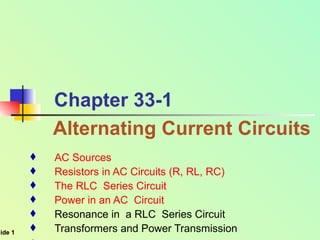
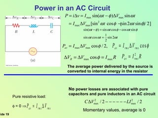
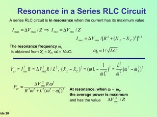
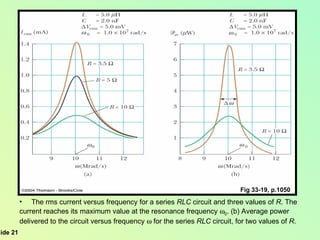
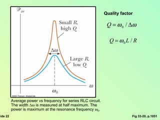
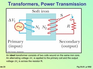
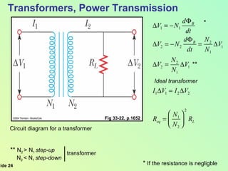
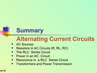

This document summarizes key concepts about alternating current (AC) circuits including resistors, inductors, and capacitors in AC circuits. It discusses the RLC series circuit, power in AC circuits, and resonance. It also covers transformers and how they are used for power transmission by stepping voltages up or down. Resonance occurs at the resonance frequency when the inductive reactance equals the capacitive reactance in a RLC series circuit, resulting in maximum current. Transformers use magnetic induction to change AC voltages efficiently for applications like power distribution.