Downloaded 410 times

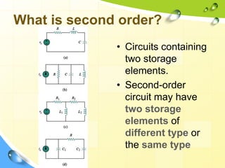


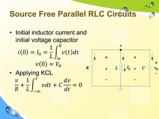


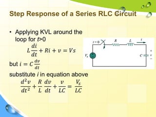
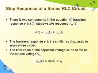
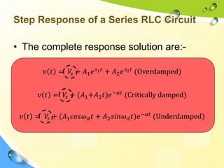
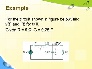


This document discusses the transient and steady state response of second-order RLC circuits when subjected to step inputs. It covers the natural response of both series and parallel RLC circuits, as well as their step responses. The key points are: - RLC circuits with two energy storage elements are considered second-order. - The transient response is solved using characteristic equations derived from KVL/KCL. Circuits can exhibit overdamped, critically damped, or underdamped behavior depending on circuit parameters. - The steady-state response is equal to the step input voltage/current. The total response is the sum of the transient and steady-state responses. - Examples are provided to