Download as PDF, PPTX


![Strain Gauge
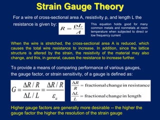
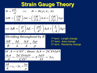
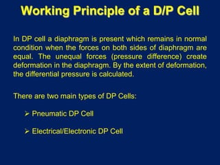
• When we apply force to a solid at rest, it will be mechanically
deformed to a certain extent. If the force is tensile, the length of the
solid will increase. If the force is compressive, the length of the solid
will decrease.
• The longitudinal or axial strain is defined as: ε = ΔL/L
• Longitudinal stress: σ = F/A (force F applied on area A)
• Stress-strain relationship within elastic limit: Hooke’s Law: E = σ/ε
E = Young’s modulus [if σ is in kg/m2, so will be E]
• When a body of length is elongated, its transverse (perpendicular)
dimension will contract. Lateral strain: εt = ΔD/D
• Poisson’s ratio: ν = Lateral strain/Longitudinal strain = εt/εa
Poisson’s ratio lie between 0 and 0.5. And mostly, it is 0.3](https://image.slidesharecdn.com/transducer2015-160217201858/85/Transducer-24-320.jpg)
![Strain Gauge
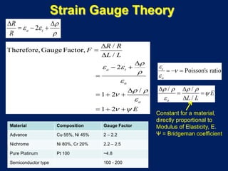
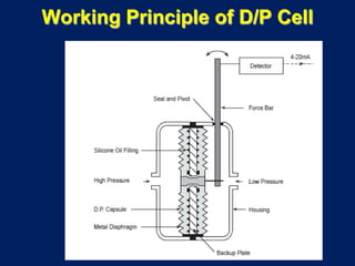
• Strain measurement is essentially measurement of very small, about
1 micrometer, displacement
• Methods:
– Mechanical: Use levers and gears to measure ΔL after
magnification [early days: extensometer uses many levers to
magnify strain so that it becomes readable]
– Electrical: Change in resistance or inductance or capacitance
– Optical: Use interference, diffraction, and scattering of light
waves
• Most commonly used method: Electrical: change in resistance:
Resistive Strain Gauges](https://image.slidesharecdn.com/transducer2015-160217201858/85/Transducer-25-320.jpg)
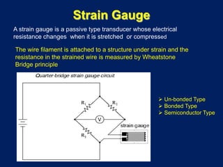
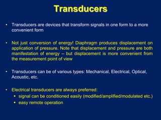
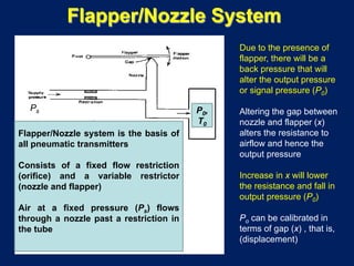
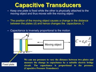
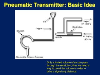
![Capacitive Transducers
d
Area=A
0
A
C
d
ε ε=
C: capacitance, pF
ε0: dielectric constant (relative permittivity) of
free space (vacuum) = 8.85 pF/m
ε: dielectric constant of insulating material
A: area of plates, m2
d: distance between plates, m
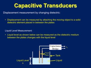
Two parallel metal plates separated by a
dielectric or insulating material:
d A A
Plate displacedd changes Dielectric material moves
(a) (b) (c)
There are 3 ways to change the capacity:
(1) variation of distance between the plates (d) [Fig. a]
(2) variation of the shared area of the plates (A ) [Fig. b]
(3) variation of dielectric constant (ε) [Fig. c]](https://image.slidesharecdn.com/transducer2015-160217201858/85/Transducer-35-320.jpg)

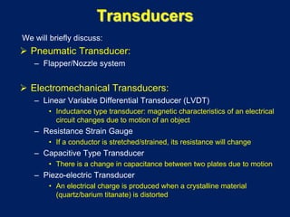
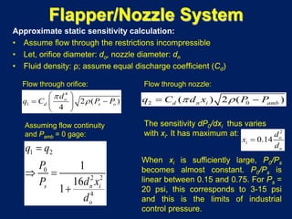
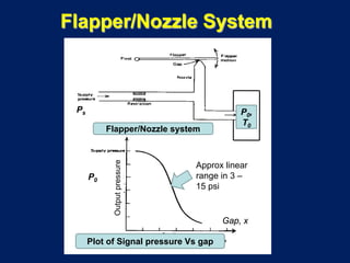
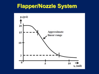
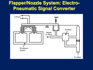
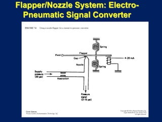
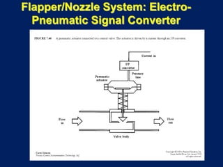
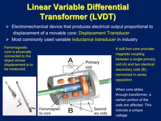
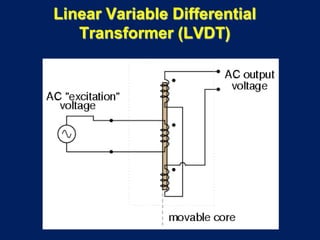
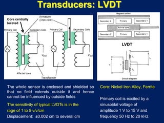
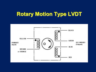
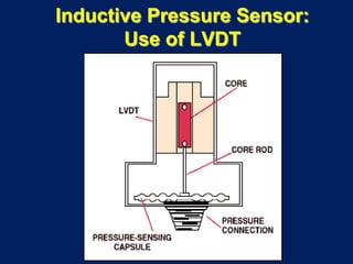
1) Transducers are devices that convert one form of energy or signal into another. Electrical transducers are preferred as they allow for easy signal conditioning and remote operation. 2) Common electromechanical transducers include the LVDT, strain gauge, and capacitive transducer. The LVDT uses the principle of variable inductance to produce an electrical output proportional to mechanical displacement. Strain gauges measure displacement or strain by detecting changes in electrical resistance. 3) The document then provides detailed explanations of the flapper/nozzle pneumatic transducer, LVDT, strain gauge theory and operation, focusing on the underlying principles and equations involved in their design and use for process measurement applications.