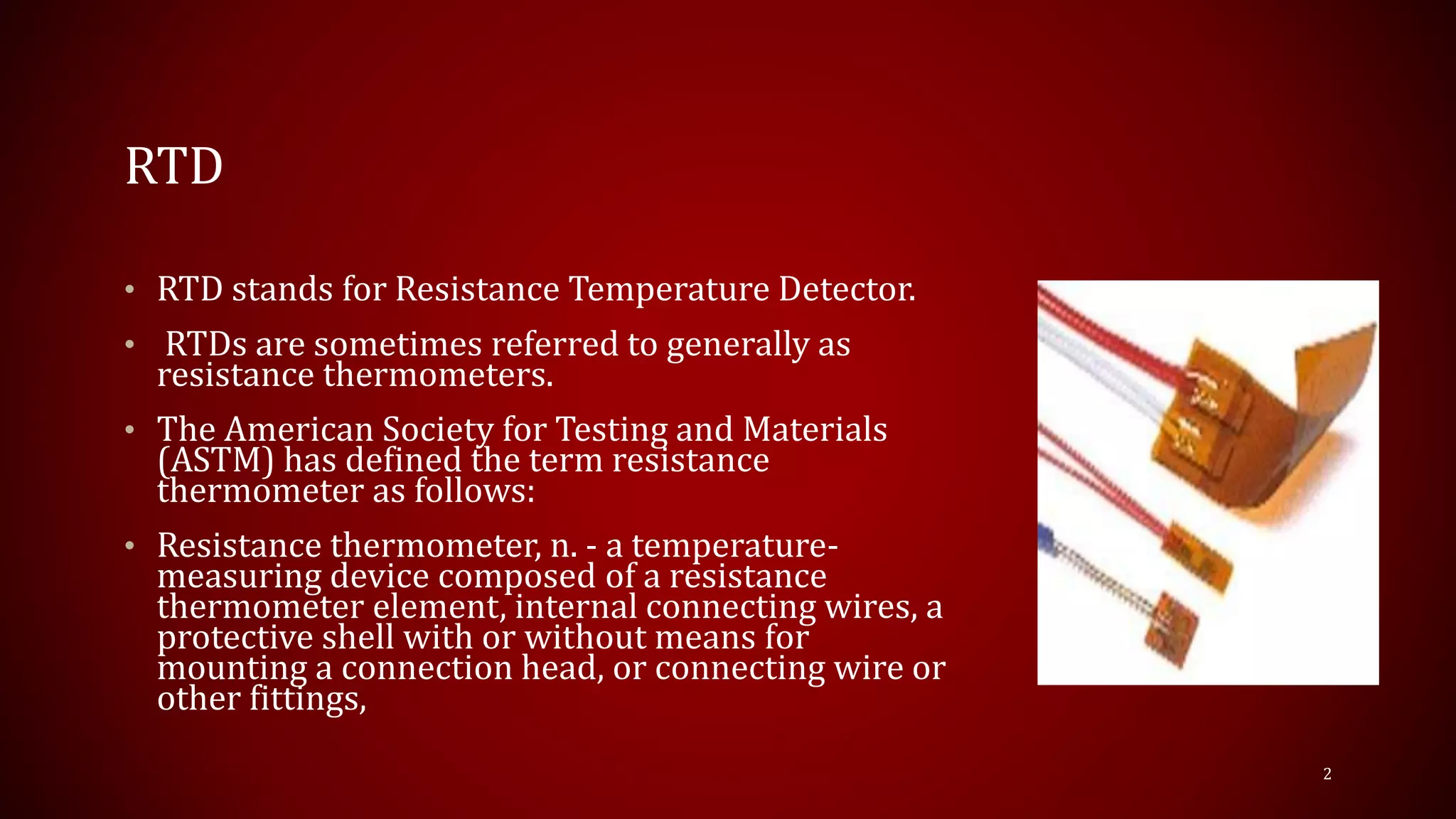
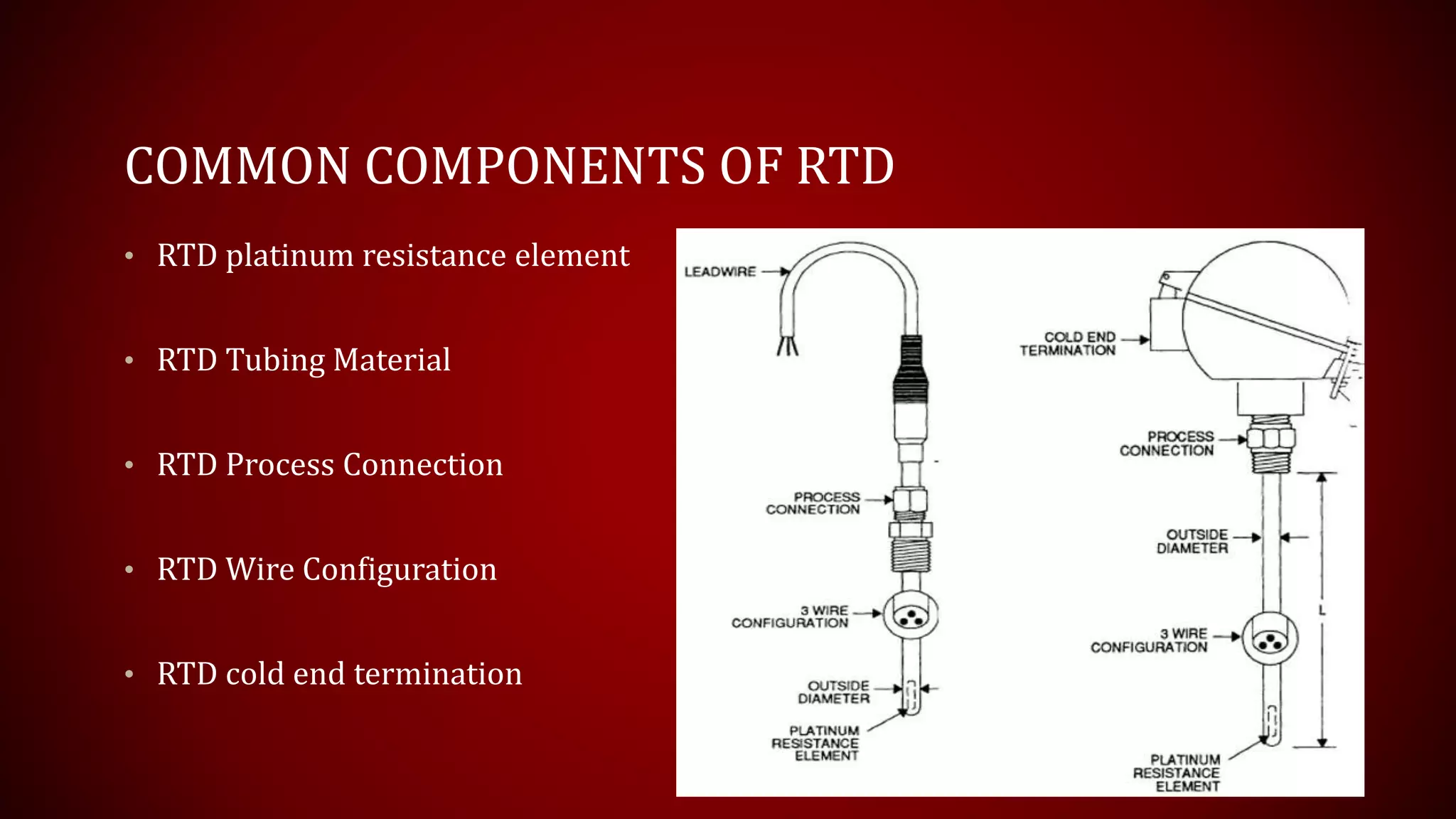
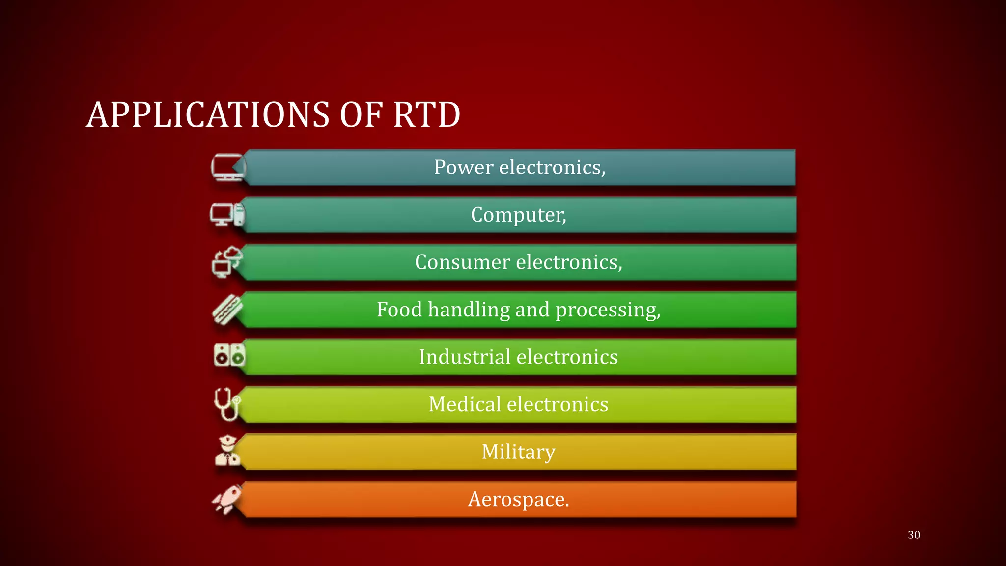
RESISTANCE TEMPERATURE
DETECTOR
Karolinekersin.E
Assistant professor
RTD
• RTD stands for Resistance Temperature Detector.
• RTDs are sometimes referred to generally as
resistance thermometers.
• The American Society for Testing and Materials
(ASTM) has defined the term resistance
thermometer as follows:
• Resistance thermometer, n. - a temperature-
measuring device composed of a resistance
thermometer element, internal connecting wires, a
protective shell with or without means for
mounting a connection head, or connecting wire or
other fittings,
2
PRINCIPLE
• An RTD is a temperature sensor which measures temperature
using the principle that the resistance of a metal changes with
temperature.
• In practice, an electrical current is transmitted through a piece
of metal (the RTD element or resistor) located in proximity to
the area where temperature is to be measured.
• The resistance value of the RTD element is then measured by an
instrument.
• This resistance value is then correlated to temperature based
upon the known resistance characteristics of the RTD element
3
• TDs work on a basic correlation between metals and
temperature.
• As the temperature of a metal increases, the metal's resistance to
the flow of electricity increases.
• Similarly, as the temperature of the RTD resistance element
increases, the electrical resistance, measured in ohms (Ω),
increases.
4
COMMON COMPONENTS OF RTD
• RTD platinum resistance element
• RTD Tubing Material
• RTD Process Connection
• RTD Wire Configuration
• RTD cold end termination
5
RTD PLATINUM RESISTANCE ELEMENT:
• This is the actual temperature sensing portion of the RTD.
Elements range in length from 1/8″ to 3″.
• The standard temperature coefficient is an alpha of .00385 and
the standard resistance is 100 Ω at 0° C.
6
RTD OUTSIDE DIAMETER
• The most common outside diameter is ¼” in the US or 6mm
(.236″) for non-US applications.
• However, outside diameters range from .063″ to .500″
7
RTD PROCESS CONNECTION:
Process connection fittings include all standard fittings used with
thermocouples (i.e. compression, welded, spring-loaded, etc.).
8
RTD WIRE CONFIGURATION
• RTDs are available in 2, 3 and 4 wire configuration.
• 3 wire configurations are the most common for industrial
applications.
• Teflon and fiberglass are the standard wire insulation materials.
• Teflon is moisture resistant and can be used up to 400° F.
Fiberglass can be used up to 1000° F.
9
RTD COLD END TERMINATION
• RTDs can terminate on the cold end with plugs, bare wires,
terminal heads and any of the reference junctions common to
thermocouples.
10
RTD ELEMENTS
• RTD elements are commonly specified according to their resistance in ohms
at zero degrees Celsius .
• The most common RTD specification is 100 Ω, which means that at 0o C the
RTD element should demonstrate 100 Ω of resistance.
• Platinum is the most commonly used metal for RTD elements due to a
number of factors, including its
• Chemical inertness,
• linear temperature versus resistance relationship,
• Temperature coefficient of resistance that is large enough to give readily measurable
resistance changes with temperature and
• Stability (in that its temperature resistance does not drastically change with time).
• Other metals that are less frequently used as the resistor elements in an
RTD include nickel, copper and Balco.
11
CONFIGURATION OF RTD
Thin film
Wire wound
Coiled element
12
CONFIGURATION OF RTD
RTD elements are typically in one of three configurations:
• A platinum or metal glass slurry film deposited or screened onto a
small flat ceramic substrate known as "thin film" RTD elements, and
• Platinum or metal wire wound on a glass or ceramic bobbin and
sealed with a coating of molten glass known as "wire wound" RTD
elements.
• A partially supported wound element which is a small coil of wire
inserted into a hole in a ceramic insulator and attached along one
side of that hole. Of the three RTD elements, the thin film is most
rugged and has become increasingly more accurate over time
13
PLATINUM RTDS
• Platinum RTDs are the most common type of RTD used in
industrial applications.
• This is because platinum has excellent corrosion resistance,
excellent long-term stability, and measures a wide range of
temperature, (-200…+850°C).
14
NICKEL RTDS
• Nickel RTDs are less expensive than platinum and have good
corrosion resistance.
• However, nickel ages more rapidly over time and loses accuracy
at higher temperatures.
• Nickel is limited to a measurement range of -80…+260°C.
15
COPPER RTDS
• Copper RTDs have the best resistance to temperature linearity of
the three RTD types, and copper is a low cost material.
• However, copper oxidizes at higher temperatures.
• Copper is limited to a measurement range of -200…+260°C
16
WIRE WOUND RTD
• In a wire wound RTD, a resistance wire
is wound around a non-conducting core,
which is usually made of ceramic.
• The sensor maker carefully trims the
length of resistance wire to achieve the
specified resistance at 0°C. This is called
the “R0” resistance.
• Next, lead wires are attached to the
resistance wire, and then a glass or
ceramic coating is applied over the wire
for protection.
• As temperature increases, the length of
resistance wire increases slightly.
17
• Care must be taken in the design to ensure that the resistance
wire does not twist or otherwise deform as temperature
increases.
• This is because mechanical strain causes a change in wire
resistance.
• Laboratory-grade RTDs used by calibration and standards
laboratories eliminate this source of error by loosely winding
resistance wire around a non-conducting support structure.
• This type of RTD can be extremely accurate, but is fragile and not
suited for most industrial applications.
18
COILED ELEMENT RTD
• In a coiled element RTD, the resistance
wire is rolled into small coils, which
loosely fit into a ceramic form that is
then filled with non-conductive
powder.
• The resistance wire is free to expand
and contract as temperature changes,
minimizing error caused by
mechanical strain.
19
• The powder increases the rate of heat transfer into the coils,
thereby improving the response time.
• Coiled element RTDs are usually protected by a metal sheath and
are used in industrial applications
20
THIN FILM RTDS
• Thin film RTDs are mass-produced and
cost less than the other RTD types.
• They are smaller, and have a faster
response time than the others, which is
desirable in many applications.
• They are made by depositing a thin
pathway of platinum on a ceramic base.
• The manufacturer adjusts the
resistance at 0°C by opening parallel
shunts in the pathway with a laser
beam.
• The more shunts are opened, the
higher is the resistance at 0°C
21
Thin film RTDs are not as accurate as the other types because:
The R0 resistance cannot be adjusted as precisely as in the other
types.
The ceramic base and platinum coating have slightly different
expansion rates.
This creates a strain error at higher temperatures.
Because thin film RTDs are smaller, the RTD excitation current
causes a slightly higher error due to RTD self-heating.
22
RTD RESISTANCE RATIO
• The term “resistance ratio” describes the average slope of
temperature vs. resistance as the RTD temperature changes from 0°C
to +100°C. The expression for resistance ratio is
(R100-R0) / R0
Where:
• R100 RTD Resistance at 100°C.
• R0 = RTD Resistance at 0°C.
Resistance ratio is affected by the type and purity of the metal used to
make the RTD
23
CHARACTERISTICS OF RTD ELEMENT
Temperature Coefficient
Nominal Resistance
Temperature Range of Application
Physical Dimensions or Size
Restrictions
Accuracy
24
MATERIAL OF RESISTANCE ELEMENT
• Several metals are quite common for use in resistance elements
and the purity of the metal affects its characteristics.
• Platinum is by far the most popular due to its linearity with
temperature.
• Other common materials are nickel and copper, although most
of these are being replaced by platinum elements.
• Other metals used, though rarely, are Balco (an iron-nickel alloy),
tungsten and iridium
25
TEMPERATURE COEFFICIENT
• The temperature coefficient of an element is a physical and
electrical property of the material.
• This is a term that describes the average resistance change per
unit of temperature from ice point to the boiling point of water
NOMINAL RESISTANCE
Nominal Resistance is the prespecified resistance value at a given
temperature
26
TEMPERATURE RANGE OF APPLICATION
• Depending on the mechanical configuration and manufacturing
methods, RTD’s may be used from -270oC to 850oC.
• Specifications for temperature range will be different, for thin
film, wire wound and glass encapsulated types
27
PHYSICAL DIMENSIONS
The most critical dimension of the element is outside diameter
(O.D.), because the element must often fit within a protective
sheath
ACCURACY
IEC 751 specifications for Platinum Resistance Thermometers
have adopted DIN 43760 requirements for accuracy
28
APPLICATIONS OF RTD
• RTD sensor is used in automotive to measure the engine
temperature, an oil level sensor, intake air temperature sensors.
• In communication and instrumentation for sensing the over the
temperature of amplifiers, transistor gain stabilizers, etc
• RTD is used in power electronics, computer, consumer
electronics, food handling and processing, industrial electronics,
medical electronics, military, and aerospace.
29
APPLICATIONS OF RTD
Power electronics,
Computer,
Consumer electronics,
Food handling and processing,
Industrial electronics
Medical electronics
Military
Aerospace.
30
THERMISTORS
• Thermistor is special type of resistor, whose resistance varies
more significantly with temperature than in standard
resistors.
• Generally, the resistance increases with the temperature for
most of the metals but the thermistors respond negatively i.e.
the resistance of the thermistors decrease with the increase
in temperature.
• This is the main principle behind thermistor.
• As the resistance of thermistors depends on the temperature,
they can be connected in the electrical circuit to measure the
temperature of the body.
31
• Thermistors are mainly used as temperature sensors, inrush current limiters, self-
resetting over-current protectors and self-regulating heating elements.
• A thermistor is made from a semiconductor material.
• It is shaped into a disc, a rod or a bead.
• Bead thermistors may be only a few millimetres in diameter.
• Some bead thermistors have the bead enclosed in a glass capsule.
32
TYPES OF THERMISTORS
Positive-temperature
coefficient (PTC)
Negative-temperature
coefficient (NTC)
33
• In PTC type thermistor, resistance increase with increase in
temperature. Whereas in NTC thermistor, resistance decrease
with increase in temperature.
• Pure metals have positive temperature coefficient (PTC) of
resistance, alloys have nearly equal zero temperature coefficient
of resistance and semi conductors have negative temperature
coefficient (NTC) of resistance.
• PTC thermistors can be used as heating elements in small
temperature controlled ovens. NTC thermistors can be used as
inrush current limiting devices in power supply circuits.
34
FEATURES OF THERMISTOR
• Thermistors are at least 10 times as sensitive as the platinum
Resistance temperature detector (RTD).
• This high sensitivity of thermistors is very useful for precision
temperature measurement, control and compensation.
• Although thermistors are very sensitive but on the other hand, it
exhibits highly non-linear characteristics of resistance versus
temperature.
• Thermistors are available in variety of sizes and shapes
• Thermistors are compact and rugged in construction.
• It is widely used in the application where temperature measurements
ranges -60 °C to 15 °C.
35
THERMISTOR CHARACTERISTICS
• Resistance increase with increase in
temperature for PTC and Resistance
decrease with increase in temperature
for NTC.
• The thermistor exhibits a highly non-
linear characteristic of resistance vs
temperature.
36
CONTD..
• There are two fundamental ways to change the temperature of
thermistor internally or externally.
• The temperature of thermistor can be changed externally by
changing the temperature of surrounding media and internally
by self-heating resulting from a current flowing through the
device.
37
THERMISTOR APPLICATIONS
• Thermistors are used in circuits to control temperature.
• They are used to compensate for the effects of temperature on
conductor or circuit performance.
• It is used in the measurement of power at high frequencies.
• Thermistors are used to provide time delay in circuits.
• It is used in the measurement of thermal conductivity.
• It is used in the measurement of composition of gases.
• Thermistors are used for the measurement of level, flow, and
pressure of liquids.
38
CONTD..
• PTC thermistors were used as timers in the degaussing coil circuit of most
CRT displays.
• A degaussing circuit using a PTC thermistor is simple, reliable (for its
simplicity), and inexpensive.
• PTC thermistors used as heater in automotive industry to provide
additional heat inside cabin with diesel engine or to heat diesel in cold
climatic conditions before engine injection.
• PTC thermistors used as current-limiting devices for circuit protection, as
replacements for fuses.
• NTC thermistors used to monitor the temperature of an incubator.
• Thermistors are also commonly used in modern digital thermostats and to
monitor the temperature of battery packs while charging.
39
CONTD..
• NTC thermistors are used in the Food Handling and Processing
industry, especially for food storage systems and food
preparation. Maintaining the correct temperature is critical to
prevent food borne illness.
• NTC thermistors are used throughout the Consumer Appliance
industry for measuring temperature. Toasters, coffee makers,
refrigerators, freezers, hair dryers, etc. all rely on thermistors for
proper temperature control.
• Hot ends of 3D printers; they monitor the heat produced and
allow the printer’s control circuitry to keep a constant
temperature for melting the plastic filament.
40
CONTD..
• NTC thermistors are used as resistance thermometers in low-
temperature measurements of the order of 10 K.
• NTC thermistors can be used as inrush-current limiting devices
in power supply circuits.
41
THANK YOU
42

RTD-RESISTANCE TEMPERATURE DETECTOR

  • 1.
  • 2.
    RTD • RTD standsfor Resistance Temperature Detector. • RTDs are sometimes referred to generally as resistance thermometers. • The American Society for Testing and Materials (ASTM) has defined the term resistance thermometer as follows: • Resistance thermometer, n. - a temperature- measuring device composed of a resistance thermometer element, internal connecting wires, a protective shell with or without means for mounting a connection head, or connecting wire or other fittings, 2
  • 3.
    PRINCIPLE • An RTDis a temperature sensor which measures temperature using the principle that the resistance of a metal changes with temperature. • In practice, an electrical current is transmitted through a piece of metal (the RTD element or resistor) located in proximity to the area where temperature is to be measured. • The resistance value of the RTD element is then measured by an instrument. • This resistance value is then correlated to temperature based upon the known resistance characteristics of the RTD element 3
  • 4.
    • TDs workon a basic correlation between metals and temperature. • As the temperature of a metal increases, the metal's resistance to the flow of electricity increases. • Similarly, as the temperature of the RTD resistance element increases, the electrical resistance, measured in ohms (Ω), increases. 4
  • 5.
    COMMON COMPONENTS OFRTD • RTD platinum resistance element • RTD Tubing Material • RTD Process Connection • RTD Wire Configuration • RTD cold end termination 5
  • 6.
    RTD PLATINUM RESISTANCEELEMENT: • This is the actual temperature sensing portion of the RTD. Elements range in length from 1/8″ to 3″. • The standard temperature coefficient is an alpha of .00385 and the standard resistance is 100 Ω at 0° C. 6
  • 7.
    RTD OUTSIDE DIAMETER •The most common outside diameter is ¼” in the US or 6mm (.236″) for non-US applications. • However, outside diameters range from .063″ to .500″ 7
  • 8.
    RTD PROCESS CONNECTION: Processconnection fittings include all standard fittings used with thermocouples (i.e. compression, welded, spring-loaded, etc.). 8
  • 9.
    RTD WIRE CONFIGURATION •RTDs are available in 2, 3 and 4 wire configuration. • 3 wire configurations are the most common for industrial applications. • Teflon and fiberglass are the standard wire insulation materials. • Teflon is moisture resistant and can be used up to 400° F. Fiberglass can be used up to 1000° F. 9
  • 10.
    RTD COLD ENDTERMINATION • RTDs can terminate on the cold end with plugs, bare wires, terminal heads and any of the reference junctions common to thermocouples. 10
  • 11.
    RTD ELEMENTS • RTDelements are commonly specified according to their resistance in ohms at zero degrees Celsius . • The most common RTD specification is 100 Ω, which means that at 0o C the RTD element should demonstrate 100 Ω of resistance. • Platinum is the most commonly used metal for RTD elements due to a number of factors, including its • Chemical inertness, • linear temperature versus resistance relationship, • Temperature coefficient of resistance that is large enough to give readily measurable resistance changes with temperature and • Stability (in that its temperature resistance does not drastically change with time). • Other metals that are less frequently used as the resistor elements in an RTD include nickel, copper and Balco. 11
  • 12.
    CONFIGURATION OF RTD Thinfilm Wire wound Coiled element 12
  • 13.
    CONFIGURATION OF RTD RTDelements are typically in one of three configurations: • A platinum or metal glass slurry film deposited or screened onto a small flat ceramic substrate known as "thin film" RTD elements, and • Platinum or metal wire wound on a glass or ceramic bobbin and sealed with a coating of molten glass known as "wire wound" RTD elements. • A partially supported wound element which is a small coil of wire inserted into a hole in a ceramic insulator and attached along one side of that hole. Of the three RTD elements, the thin film is most rugged and has become increasingly more accurate over time 13
  • 14.
    PLATINUM RTDS • PlatinumRTDs are the most common type of RTD used in industrial applications. • This is because platinum has excellent corrosion resistance, excellent long-term stability, and measures a wide range of temperature, (-200…+850°C). 14
  • 15.
    NICKEL RTDS • NickelRTDs are less expensive than platinum and have good corrosion resistance. • However, nickel ages more rapidly over time and loses accuracy at higher temperatures. • Nickel is limited to a measurement range of -80…+260°C. 15
  • 16.
    COPPER RTDS • CopperRTDs have the best resistance to temperature linearity of the three RTD types, and copper is a low cost material. • However, copper oxidizes at higher temperatures. • Copper is limited to a measurement range of -200…+260°C 16
  • 17.
    WIRE WOUND RTD •In a wire wound RTD, a resistance wire is wound around a non-conducting core, which is usually made of ceramic. • The sensor maker carefully trims the length of resistance wire to achieve the specified resistance at 0°C. This is called the “R0” resistance. • Next, lead wires are attached to the resistance wire, and then a glass or ceramic coating is applied over the wire for protection. • As temperature increases, the length of resistance wire increases slightly. 17
  • 18.
    • Care mustbe taken in the design to ensure that the resistance wire does not twist or otherwise deform as temperature increases. • This is because mechanical strain causes a change in wire resistance. • Laboratory-grade RTDs used by calibration and standards laboratories eliminate this source of error by loosely winding resistance wire around a non-conducting support structure. • This type of RTD can be extremely accurate, but is fragile and not suited for most industrial applications. 18
  • 19.
    COILED ELEMENT RTD •In a coiled element RTD, the resistance wire is rolled into small coils, which loosely fit into a ceramic form that is then filled with non-conductive powder. • The resistance wire is free to expand and contract as temperature changes, minimizing error caused by mechanical strain. 19
  • 20.
    • The powderincreases the rate of heat transfer into the coils, thereby improving the response time. • Coiled element RTDs are usually protected by a metal sheath and are used in industrial applications 20
  • 21.
    THIN FILM RTDS •Thin film RTDs are mass-produced and cost less than the other RTD types. • They are smaller, and have a faster response time than the others, which is desirable in many applications. • They are made by depositing a thin pathway of platinum on a ceramic base. • The manufacturer adjusts the resistance at 0°C by opening parallel shunts in the pathway with a laser beam. • The more shunts are opened, the higher is the resistance at 0°C 21
  • 22.
    Thin film RTDsare not as accurate as the other types because: The R0 resistance cannot be adjusted as precisely as in the other types. The ceramic base and platinum coating have slightly different expansion rates. This creates a strain error at higher temperatures. Because thin film RTDs are smaller, the RTD excitation current causes a slightly higher error due to RTD self-heating. 22
  • 23.
    RTD RESISTANCE RATIO •The term “resistance ratio” describes the average slope of temperature vs. resistance as the RTD temperature changes from 0°C to +100°C. The expression for resistance ratio is (R100-R0) / R0 Where: • R100 RTD Resistance at 100°C. • R0 = RTD Resistance at 0°C. Resistance ratio is affected by the type and purity of the metal used to make the RTD 23
  • 24.
    CHARACTERISTICS OF RTDELEMENT Temperature Coefficient Nominal Resistance Temperature Range of Application Physical Dimensions or Size Restrictions Accuracy 24
  • 25.
    MATERIAL OF RESISTANCEELEMENT • Several metals are quite common for use in resistance elements and the purity of the metal affects its characteristics. • Platinum is by far the most popular due to its linearity with temperature. • Other common materials are nickel and copper, although most of these are being replaced by platinum elements. • Other metals used, though rarely, are Balco (an iron-nickel alloy), tungsten and iridium 25
  • 26.
    TEMPERATURE COEFFICIENT • Thetemperature coefficient of an element is a physical and electrical property of the material. • This is a term that describes the average resistance change per unit of temperature from ice point to the boiling point of water NOMINAL RESISTANCE Nominal Resistance is the prespecified resistance value at a given temperature 26
  • 27.
    TEMPERATURE RANGE OFAPPLICATION • Depending on the mechanical configuration and manufacturing methods, RTD’s may be used from -270oC to 850oC. • Specifications for temperature range will be different, for thin film, wire wound and glass encapsulated types 27
  • 28.
    PHYSICAL DIMENSIONS The mostcritical dimension of the element is outside diameter (O.D.), because the element must often fit within a protective sheath ACCURACY IEC 751 specifications for Platinum Resistance Thermometers have adopted DIN 43760 requirements for accuracy 28
  • 29.
    APPLICATIONS OF RTD •RTD sensor is used in automotive to measure the engine temperature, an oil level sensor, intake air temperature sensors. • In communication and instrumentation for sensing the over the temperature of amplifiers, transistor gain stabilizers, etc • RTD is used in power electronics, computer, consumer electronics, food handling and processing, industrial electronics, medical electronics, military, and aerospace. 29
  • 30.
    APPLICATIONS OF RTD Powerelectronics, Computer, Consumer electronics, Food handling and processing, Industrial electronics Medical electronics Military Aerospace. 30
  • 31.
    THERMISTORS • Thermistor isspecial type of resistor, whose resistance varies more significantly with temperature than in standard resistors. • Generally, the resistance increases with the temperature for most of the metals but the thermistors respond negatively i.e. the resistance of the thermistors decrease with the increase in temperature. • This is the main principle behind thermistor. • As the resistance of thermistors depends on the temperature, they can be connected in the electrical circuit to measure the temperature of the body. 31
  • 32.
    • Thermistors aremainly used as temperature sensors, inrush current limiters, self- resetting over-current protectors and self-regulating heating elements. • A thermistor is made from a semiconductor material. • It is shaped into a disc, a rod or a bead. • Bead thermistors may be only a few millimetres in diameter. • Some bead thermistors have the bead enclosed in a glass capsule. 32
  • 33.
    TYPES OF THERMISTORS Positive-temperature coefficient(PTC) Negative-temperature coefficient (NTC) 33
  • 34.
    • In PTCtype thermistor, resistance increase with increase in temperature. Whereas in NTC thermistor, resistance decrease with increase in temperature. • Pure metals have positive temperature coefficient (PTC) of resistance, alloys have nearly equal zero temperature coefficient of resistance and semi conductors have negative temperature coefficient (NTC) of resistance. • PTC thermistors can be used as heating elements in small temperature controlled ovens. NTC thermistors can be used as inrush current limiting devices in power supply circuits. 34
  • 35.
    FEATURES OF THERMISTOR •Thermistors are at least 10 times as sensitive as the platinum Resistance temperature detector (RTD). • This high sensitivity of thermistors is very useful for precision temperature measurement, control and compensation. • Although thermistors are very sensitive but on the other hand, it exhibits highly non-linear characteristics of resistance versus temperature. • Thermistors are available in variety of sizes and shapes • Thermistors are compact and rugged in construction. • It is widely used in the application where temperature measurements ranges -60 °C to 15 °C. 35
  • 36.
    THERMISTOR CHARACTERISTICS • Resistanceincrease with increase in temperature for PTC and Resistance decrease with increase in temperature for NTC. • The thermistor exhibits a highly non- linear characteristic of resistance vs temperature. 36
  • 37.
    CONTD.. • There aretwo fundamental ways to change the temperature of thermistor internally or externally. • The temperature of thermistor can be changed externally by changing the temperature of surrounding media and internally by self-heating resulting from a current flowing through the device. 37
  • 38.
    THERMISTOR APPLICATIONS • Thermistorsare used in circuits to control temperature. • They are used to compensate for the effects of temperature on conductor or circuit performance. • It is used in the measurement of power at high frequencies. • Thermistors are used to provide time delay in circuits. • It is used in the measurement of thermal conductivity. • It is used in the measurement of composition of gases. • Thermistors are used for the measurement of level, flow, and pressure of liquids. 38
  • 39.
    CONTD.. • PTC thermistorswere used as timers in the degaussing coil circuit of most CRT displays. • A degaussing circuit using a PTC thermistor is simple, reliable (for its simplicity), and inexpensive. • PTC thermistors used as heater in automotive industry to provide additional heat inside cabin with diesel engine or to heat diesel in cold climatic conditions before engine injection. • PTC thermistors used as current-limiting devices for circuit protection, as replacements for fuses. • NTC thermistors used to monitor the temperature of an incubator. • Thermistors are also commonly used in modern digital thermostats and to monitor the temperature of battery packs while charging. 39
  • 40.
    CONTD.. • NTC thermistorsare used in the Food Handling and Processing industry, especially for food storage systems and food preparation. Maintaining the correct temperature is critical to prevent food borne illness. • NTC thermistors are used throughout the Consumer Appliance industry for measuring temperature. Toasters, coffee makers, refrigerators, freezers, hair dryers, etc. all rely on thermistors for proper temperature control. • Hot ends of 3D printers; they monitor the heat produced and allow the printer’s control circuitry to keep a constant temperature for melting the plastic filament. 40
  • 41.
    CONTD.. • NTC thermistorsare used as resistance thermometers in low- temperature measurements of the order of 10 K. • NTC thermistors can be used as inrush-current limiting devices in power supply circuits. 41
  • 42.