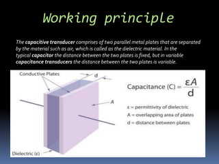
SESSION: 2017-18
CAPACITIVE TYPE TRANSDUCER
Submitted by:-
Krishna Kant Nayak
Student of MNIT, Jaipur
Introduction
Work Principle
Parameters of capacitive
transducer
Application of capacitive
transducer
Introduction
 Moreover, the capacitive transducer or
sensor is nothing but the capacitor with
variable capacitance
“Capacitive type means using capacitance and
transducer means a device that converts variations
in a physical quantity, into an electrical signal”
Working principle
The capacitive transducer comprises of two parallel metal plates that are separated
by the material such as air, which is called as the dielectric material. In the
typical capacitor the distance between the two plates is fixed, but in variable
capacitance transducers the distance between the two plates is variable.
The capacitanceC between the two plates of capacitive transducers is
given by:
C= (ε0 x εr xA)/ d
Where,
C -The variable capacitance transducer
ε0 - absolute permittivity
εr - relative permittivity
The product of ε0 & εr is also called as the dielectric constant of the
capacitive transducer.
A - area of the plates
D - distance between the plates
 Changing Area of the Plates of CapacitiveTransducers
 Changing Distance between the Plates of Capacitive
Transducers
 Changing Dielectric Constant type of Capacitive
Transducers
Parameters for Capacitive
Transducers
Application of capacitive
transducer
Capacitive type transducers has wide range of applications in
which s0me of them are:
 In Microphones
 In Semiconductor Industries
 In Detecting Dynamic Motion
In Microphones
An increase of distance between the parallel plates will
decrease the capacitance value correspondingly.
This transducer is used to convert the value of displacement
or change in pressure in terms of frequency.
• As shown in the figure , A capacitive transducer has a
static plate and a deflected flexible diaphragm with a
dielectric in between.When a force is exerted to the outer
side of the diaphragm the distance between the
diaphragm and the static plate changes.This produces a
capacitance which is measured using an alternating
current bridge or a tank circuit.
• A tank circuit is more preferred because it produces a
change in frequency according to the change in
capacitance.This value of frequency will be
corresponding to the displacement or force given to the
input.
Capacitive sensors are used for the precise
positioning of semiconductor down to nanometer
level for exposure in different electrical and
electronic circuits.
Semiconductor industry
Capacitive transducers are ideal for the
measurement of dynamics of a continuously
moving target such as rotating spindles or
vibrating element like in disc drive spindles.
Detecting Dynamic Motion
 Liquid level measurement by changing the
capacitance between two conductive plates.
 Capacitors are common force sensors.
 Commonly used forThickness measurement in a
noncontact fashion.
Advantages
 High sensitivity
 Can detect upto 10^-14 m displacements
 Low power requirement
 High resolution
 Low cost
 Easy to integrate into ICs
Disadvantages
 Performance is severely effected by dirt and
other contaminants.
 The metallic part must be insulated from
each other.
 Affected by temperature and humidity
 Sensitivity to noise
 Difficulties in designing
 Non-linearity
References
 www.electronicdesign.com
 www.instrumentationtoday.com
 https://en.wikipedia.org
 http://www.brighthubengineering.com/hvac
/53147-how-capacitive-transducers-work/
 http://kalpanatamvada.tripod.com/
Capacitive Type Transducer

Capacitive Type Transducer

  • 1.
    SESSION: 2017-18 CAPACITIVE TYPETRANSDUCER Submitted by:- Krishna Kant Nayak Student of MNIT, Jaipur
  • 2.
    Introduction Work Principle Parameters ofcapacitive transducer Application of capacitive transducer
  • 3.
    Introduction  Moreover, thecapacitive transducer or sensor is nothing but the capacitor with variable capacitance “Capacitive type means using capacitance and transducer means a device that converts variations in a physical quantity, into an electrical signal”
  • 4.
    Working principle The capacitivetransducer comprises of two parallel metal plates that are separated by the material such as air, which is called as the dielectric material. In the typical capacitor the distance between the two plates is fixed, but in variable capacitance transducers the distance between the two plates is variable.
  • 5.
    The capacitanceC betweenthe two plates of capacitive transducers is given by: C= (ε0 x εr xA)/ d Where, C -The variable capacitance transducer ε0 - absolute permittivity εr - relative permittivity The product of ε0 & εr is also called as the dielectric constant of the capacitive transducer. A - area of the plates D - distance between the plates
  • 6.
     Changing Areaof the Plates of CapacitiveTransducers  Changing Distance between the Plates of Capacitive Transducers  Changing Dielectric Constant type of Capacitive Transducers Parameters for Capacitive Transducers
  • 7.
    Application of capacitive transducer Capacitivetype transducers has wide range of applications in which s0me of them are:  In Microphones  In Semiconductor Industries  In Detecting Dynamic Motion
  • 8.
    In Microphones An increaseof distance between the parallel plates will decrease the capacitance value correspondingly. This transducer is used to convert the value of displacement or change in pressure in terms of frequency.
  • 9.
    • As shownin the figure , A capacitive transducer has a static plate and a deflected flexible diaphragm with a dielectric in between.When a force is exerted to the outer side of the diaphragm the distance between the diaphragm and the static plate changes.This produces a capacitance which is measured using an alternating current bridge or a tank circuit. • A tank circuit is more preferred because it produces a change in frequency according to the change in capacitance.This value of frequency will be corresponding to the displacement or force given to the input.
  • 10.
    Capacitive sensors areused for the precise positioning of semiconductor down to nanometer level for exposure in different electrical and electronic circuits. Semiconductor industry
  • 11.
    Capacitive transducers areideal for the measurement of dynamics of a continuously moving target such as rotating spindles or vibrating element like in disc drive spindles. Detecting Dynamic Motion
  • 12.
     Liquid levelmeasurement by changing the capacitance between two conductive plates.  Capacitors are common force sensors.  Commonly used forThickness measurement in a noncontact fashion.
  • 13.
    Advantages  High sensitivity Can detect upto 10^-14 m displacements  Low power requirement  High resolution  Low cost  Easy to integrate into ICs
  • 14.
    Disadvantages  Performance isseverely effected by dirt and other contaminants.  The metallic part must be insulated from each other.  Affected by temperature and humidity  Sensitivity to noise  Difficulties in designing  Non-linearity
  • 15.
    References  www.electronicdesign.com  www.instrumentationtoday.com https://en.wikipedia.org  http://www.brighthubengineering.com/hvac /53147-how-capacitive-transducers-work/  http://kalpanatamvada.tripod.com/