


![Resistance vs Temperature
Approximations
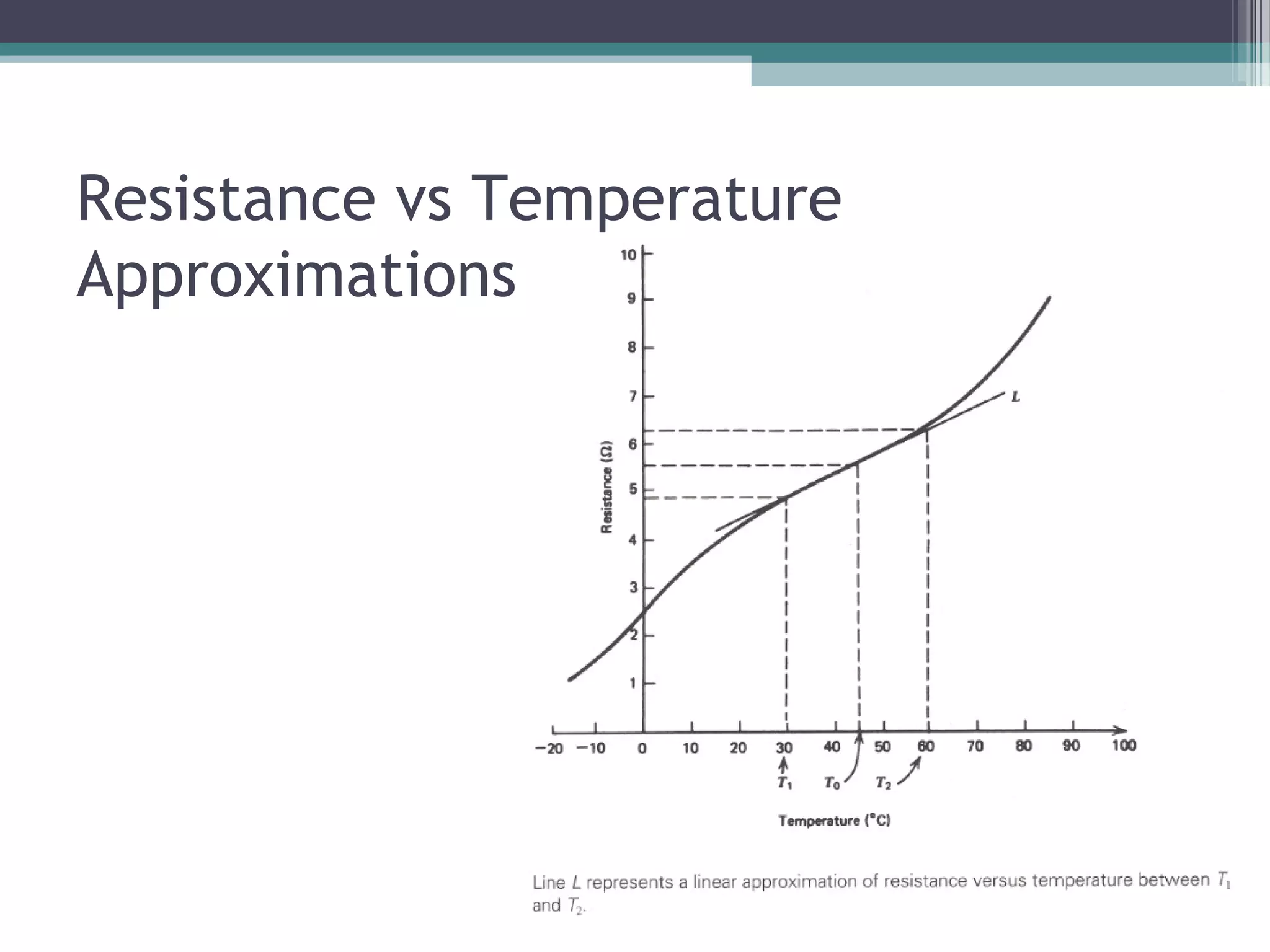
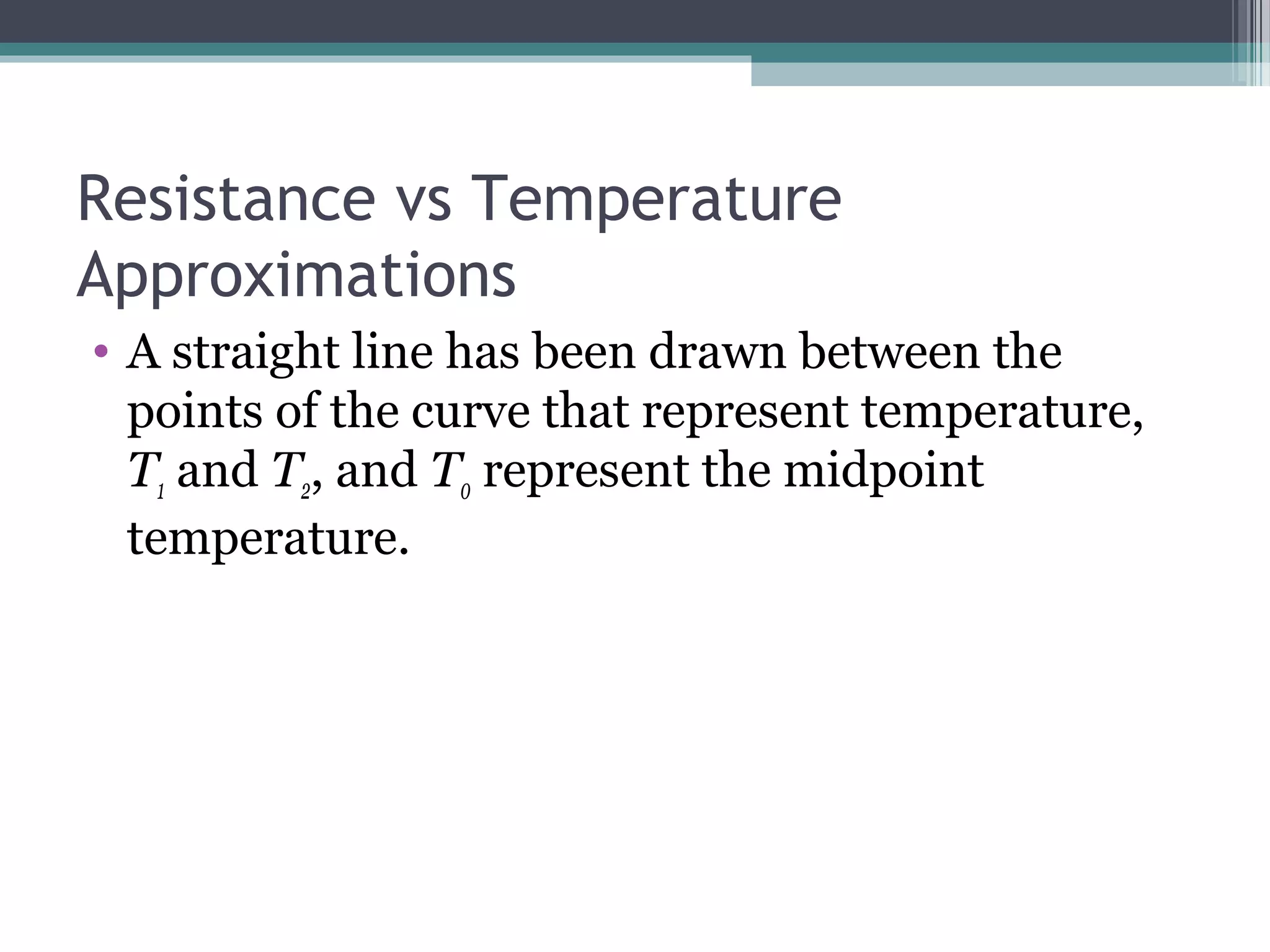
Straight line equation
R(T) = approximation of resistance at
temperature T
R(T0) = resistance at temperature T0
αo = fractional change in resistance per
degree of temperature at T0
ΔT = T - T0
21]1)[()( TTTTTRTR oo <<∆+= α](https://image.slidesharecdn.com/transducermain222-150220113105-conversion-gate02/75/Transducer-main-58-2048.jpg)

![RTD – quadratic approximation
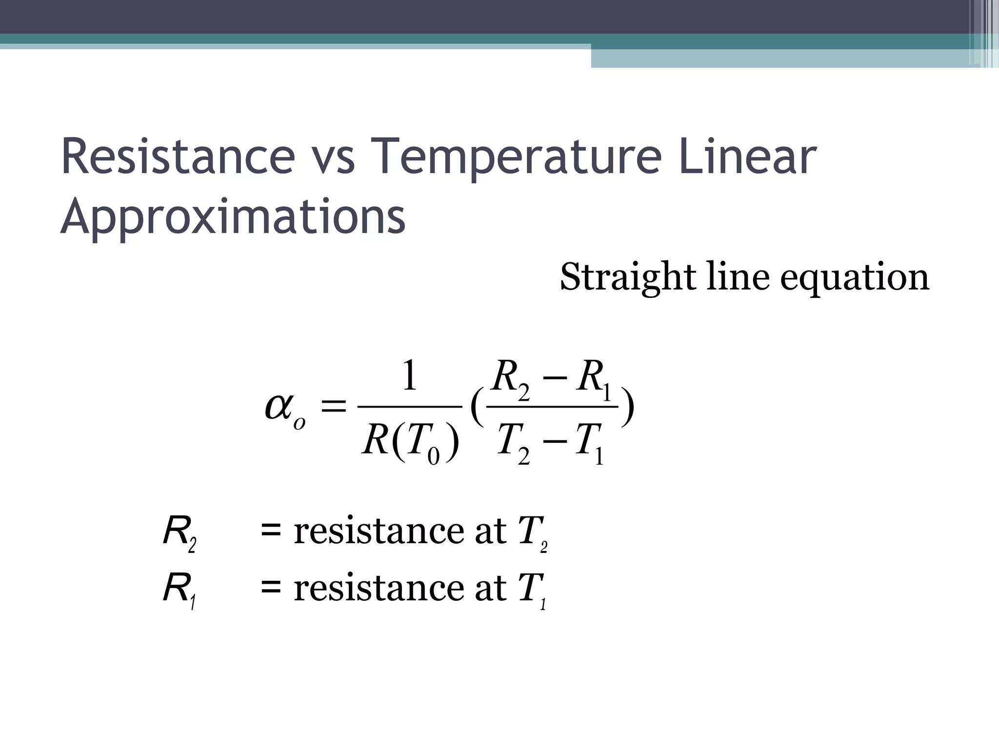
R(T) = quadratic approximation of
resistance at temperature T
R(T0) = resistance at temperature T0
α1 = linear fractional change in resistance
with temperature
α2 = quadratic fractional change in
resistance with temperature
ΔT = T - T0
21
2
21 ])(1)[()( TTTTTTRTR o <<∆+∆+= αα](https://image.slidesharecdn.com/transducermain222-150220113105-conversion-gate02/75/Transducer-main-62-2048.jpg)


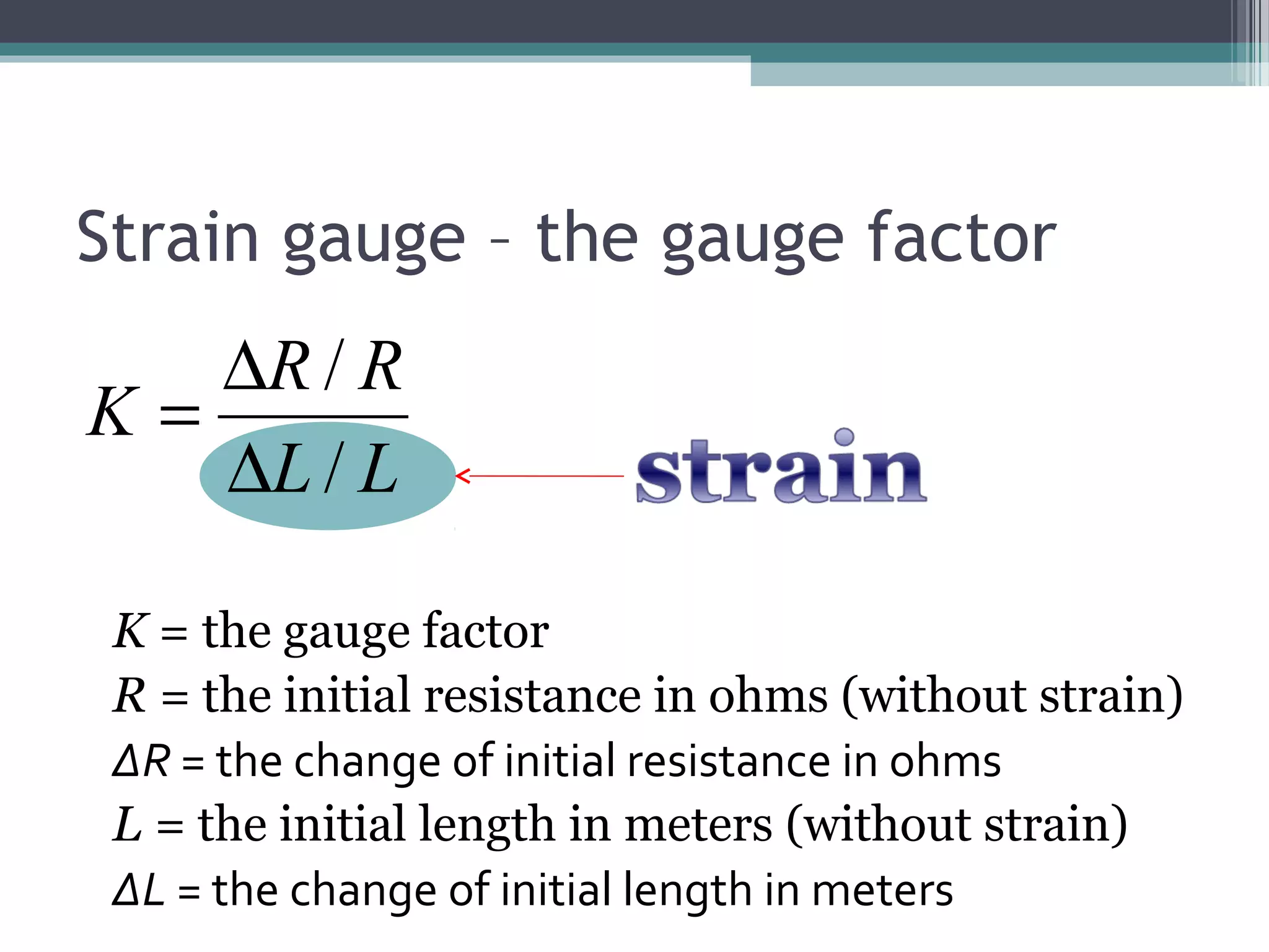


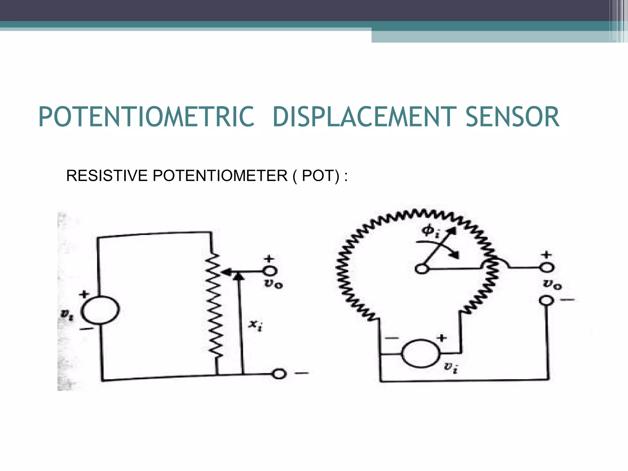
This document provides an overview of sensors and instrumentation. It discusses key concepts like measurement, instruments, transducers, sensors, and different types of sensors like pressure sensors, displacement sensors, and strain gauges. Measurement involves quantitatively comparing an unknown quantity to a standard unit. Instruments are devices that measure physical quantities and can be mechanical, electrical or electronic. Transducers convert one form of energy to another while sensors measure energy levels and output electrical signals.