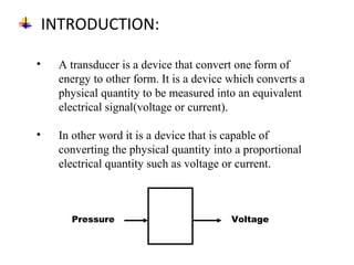
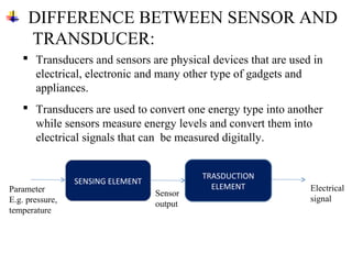
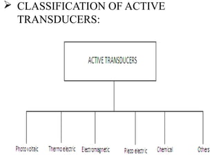
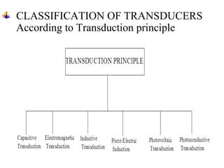
C.K. PITHAWALA COLLEGE OF
ENGINEERING AND
TECHNOLOGY
PREPARED BY:
TAILOR DIGEN K. 160093111016
SARANG SACHIN A. 160093111015
PATEL HARISH S. 160093111012
AKHIANIA PRATIK B. 160093111001
SUBJECT: Electronic measurement &instrumentation
TOPIC: Transducer
BRANCH: Electronics and Communication
GROUP: G1A_5
INTRODUCTION:
• A transducer is a device that convert one form of
energy to other form. It is a device which converts a
physical quantity to be measured into an equivalent
electrical signal(voltage or current).
• In other word it is a device that is capable of
converting the physical quantity into a proportional
electrical quantity such as voltage or current.
Pressure Voltage
• Now if the core is displaced from its null
position toward sec1 then flux linked to sec1
increases and flux linked to sec2 decreases.
Therefore eo1 > eo2 and the output voltage of
LVDT eo will be positive
• Similarly if the core is displaced toward sec2
then the eo2 > eo1 and the output voltage of
LVDT eo will be negative.
DIFFERENCE BETWEEN SENSOR AND
TRANSDUCER:
SENSING ELEMENT
TRASDUCTION
ELEMENTParameter
E.g. pressure,
temperature
Electrical
signal
Sensor
output
 Transducers and sensors are physical devices that are used in
electrical, electronic and many other type of gadgets and
appliances.
 Transducers are used to convert one energy type into another
while sensors measure energy levels and convert them into
electrical signals that can be measured digitally.
TRANSDUCERS SELECTION FACTORS:
1. Operating Principle: The transducer are many times selected
on the basis of operating principle used by them. The
operating principle used may be resistive, inductive,
capacitive , optoelectronic, piezo electric etc.
2. Sensitivity: The transducer must be sensitive enough to
produce detectable output.
3. Operating Range: The transducer should maintain the range
requirement and have a good resolution over the entire range.
4. Accuracy: High accuracy is assured.
5. Cross sensitivity: It has to be taken into account when
measuring mechanical quantities. There are situation where
the actual quantity is being measured is in one plane and the
transducer is subjected to variation in another plan.
6. Errors: The transducer should maintain the expected input-
output relationship as described by the transfer function so as
to avoid errors.
7. Transient and frequency response : The transducer should meet
the desired time domain specification like peak overshoot, rise
time, setting time and small dynamic error.
8. Loading Effects: The transducer should have a high input
impedance and low output impedance to avoid loading effects.
9. Environmental Compatibility: It should be assured that the
transducer selected to work under specified environmental
conditions maintains its input- output relationship and does not
break down.
10. Insensitivity to unwanted signals: The transducer should be
minimally sensitive to unwanted signals and highly sensitive to
desired signals.
CLASSIFICATION OF TRANSDUCERS:
• The transducers can be classified as:
I. Active and passive transducers.
II. Analog and digital transducers.
III. On the basis of transduction principle used.
IV. Primary and secondary transducer
V. Transducers and inverse transducers.
 Active transducers :
These transducers do not need any external source of power for
their operation. Therefore they are also called as self generating
type transducers.
I.The active transducer are self generating devices which operate
under the energy conversion principle.
II.As the output of active transducers we get an equivalent
electrical output signal e.g. temperature or strain to electric
potential, without any external source of energy being used.
ACTIVE AND PASSIVE TRANSDUCERS:
 CLASSIFICATION OF ACTIVE
TRANSDUCERS:
 Passive Transducers :
These transducers need external source of power for their
operation. So they are not self generating type transducers.
I. A DC power supply or an audio frequency generator is used
as an external power source.
II. These transducers produce the output signal in the form of
variation in resistance, capacitance, inductance or some other
electrical parameter in response to the quantity to be
measured
 CLASSIFICATION OF PASSIVE
TRANSDUCERS:
PRIMARY AND SECONDARY
TRANSDUCERS:
• Some transducers contain the mechanical as well as electrical
device. The mechanical device converts the physical quantity to be
measured into a mechanical signal. Such mechanical device are
called as the primary transducers, because they deal with the
physical quantity to be measured.
• The electrical device then convert this mechanical signal into a
corresponding electrical signal. Such electrical device are known
as secondary transducers.
• Ref fig in which the diaphragm act as primary transducer. It
convert pressure (the quantity to be measured) into
displacement(the mechanical signal).
• The displacement is then converted into change in resistance using
strain gauge. Hence strain gauge acts as the secondary transducer.
CLASSIFICATION OF TRANSDUCERS
According to Transduction principle
 CAPACITIVE TRANSDUCER:
• In capacitive transduction transducers the measured is
converted to a change in the capacitance.
• A typical capacitor is comprised of two parallel plates of
conducting material separated by an electrical insulating
material called a dielectric. The plates and the dielectric
may be either flattened or rolled.
• The purpose of the dielectric is to help the two parallel
plates maintain their stored electrical charges.
• The relationship between the capacitance and the size of
capacitor plate, amount of plate separation, and the
dielectric is given by
C = ε0 εr A / d
d is the separation distance of plates (m)
C is the capacitance (F, Farad)
ε0 : absolute permittivity of vacuum
εr : relative permittivity
A is the effective (overlapping) area of capacitor
plates (m2)
d
Area=A
Either A, d or ε can be varied.
 ELECTROMAGNETIC TRANSDUCTION:
 In electromagnetic transduction, the measure and is converted to
voltage induced in conductor by change in the magnetic flux, in
absence of excitation.
 The electromagnetic transducer are self generating active
transducers.
 The motion between a piece of magnet and an electromagnet is
responsible for the change in flux
Current induced in a coil.
 INDUCTIVE TRANSDUCER:
 In inductive transduction, the measure and is converted into a
change in the self inductance of a single coil. It is achieved by
displacing the core of the coil that is attached to a mechanical
sensing element
 PIEZO ELECTRIC INDUCTION :
 In piezoelectric induction the measure and is converted into a
change in electrostatic charge q or voltage V generated by
crystals when mechanically it is stressed as shown in fig.
 PHOTOVOLTAIC TRANSDUCTION :
 In photovoltaic transduction the measure and is converted to
voltage generated when the junction between dissimilar
material is illuminated as shown in fig.
n-type
semiconductor
p-type
semiconductor
+ + + + + + + + + + + + + +
+- - - - - - - - - - - - - - - - - -
Physics of Photovoltaic Generation
Depletion Zone
 PHOTO CONDUCTIVE TRANSDUCTION :
• In photoconductive transduction the measure and is
converted to change in resistance of semiconductor material
by the change in light incident on the material.
Transducer and Inverse Transducer
 TRANSDUCER:
Transducers convert non electrical quantity to electrical
quantity.
 INVERSE TRANSDUCER:
Inverse transducers convert electrical quantity to a non
quantity
 PASSIVE TRANSDUCERS
• Resistive transducers :
– Resistive transducers are those transducers in which the
resistance change due to the change in some physical
phenomenon.
– The resistance of a metal conductor is expressed by a
simple equation.
– R = ρL/A
– Where R = resistance of conductor in Ω
L = length of conductor in m
A = cross sectional area of conductor in m2
ρ = resistivity of conductor material in Ω-m.
RESISTIVE TRANSDUCER
There are 4 type of resistive transducers.
1. Potentiometers (POT)
2. Strain gauge
3. Thermistors
4. Resistance thermometer
 POTENTIOMETER:
• The potentiometer are used for voltage division. They consist of a
resistive element provided with a sliding contact. The sliding contact
is called as wiper.
• The contact motion may be linear or rotational or combination of the
two. The combinational potentiometer have their resistive element in
helix form and are called helipots.
• Fig shows a linear pot and a rotary pot.
 STRAIN GAUGE:
• The strain gauge is a passive, resistive transducer which
converts the mechanical elongation and compression into a
resistance change.
• This change in resistance takes place due to variation in length
and cross sectional area of the gauge wire, when an external
force acts on it.
 TYPES OF STRAIN GAUGE:
• The type of strain gauge are as
1. Wire gauge
I. Unbounded
II. Bonded
III. Foil type
2. Semiconductor gauge
 RESISTANCE THERMOMETER:
• Resistance of metal increase with increases in
temperature. Therefore metals are said to have a
positive temperature coefficient of resistivity.
• Fig shows the simplest type of open wire construction
of platinum résistance thermometer. The platinum
wire is wound in the form of spirals on an insulating
material such as mica or ceramic.
• This assembly is then placed at the tip of probe
• This wire is in direct contact with the gas or liquid
whose temperature is to be measured.
• The resistance of the platinum wire changes with the
change in temperature of the gas or liquid
• This type of sensor have a positive temperature
coefficient of resistivity as they are made from metals
they are also known as resistance temperature
detector
• Resistance thermometer are generally of probe type
for immersion in medium whose temperature is to be
measured or controlled.
 THERMISTOR
•Thermistor is a contraction of a term “thermal resistor”.
•Thermistor are temperature dependent resistors. They are
made of semiconductor material which have negative
temperature coefficient of resistivity i.e. their resistance
decreases with increase of temperature.
•Thermistor are widely used in application which involve
measurement in the range of 0-60º Thermistor are composed
of sintered mixture of metallic oxides such as magnese,
nickle, cobalt, copper, iron and uranium
•The thermistor may be in the form of beads, rods and
discs.
•The thermistor provide a large change in resistance for
small change in temperature. In some cases the
resistance of themistor at room temperature may
decreases as much as 6% for each 1ºC rise in
temperature.
 Thermocouples:
See beck Effect
When a pair of dissimilar metals are joined at one end, and there is a
temperature difference between the joined ends and the open ends,
thermal emf is generated, which can be measured in the open ends.
This forms the basis of thermocouples.
VARIABLE-INDUCTANCE
TRANSDUCERS
 An inductive electromechanical transducer is a transducer
which converts the physical motion into the change in
inductance.
 Inductive transducers are mainly used for displacement
measurement.
LINEAR VARIABLE DIFFERENTIAL
TRANSFORMER(LVDT)
 AN LVDT transducer comprises a coil former on to which three
coils are wound.
 The primary coil is excited with an AC current, the secondary
coils are wound such that when a ferrite core is in the central
linear position, an equal voltage is induced in to each coil.
 The secondary are connected in opposite so that in the central
position the outputs of the secondary cancels each other out.
 The excitation is applied to the primary winding and the
armature assists the induction of current in to secondary coils.
 When the core is exactly at the center of the coil then the flux
linked to both the secondary winding will be equal. Due to equal
flux linkage the secondary induced voltages (eo1 & eo2) are
equal but they have opposite polarities. Output voltage eo is
therefore zero. This position is called “null position”
 Now if the core is displaced from its null position
toward sec1 then flux linked to sec1 increases and
flux linked to sec2 decreases. Therefore eo1 > eo2
and the output voltage of LVDT eo will be positive
 Similarly if the core is displaced toward sec2 then the
eo2 > eo1 and the output voltage of LVDT eo will be
negative.
GUIDED BY:
Prof. Vijayendra A.

EMI-tansducers

  • 1.
    C.K. PITHAWALA COLLEGEOF ENGINEERING AND TECHNOLOGY PREPARED BY: TAILOR DIGEN K. 160093111016 SARANG SACHIN A. 160093111015 PATEL HARISH S. 160093111012 AKHIANIA PRATIK B. 160093111001 SUBJECT: Electronic measurement &instrumentation TOPIC: Transducer BRANCH: Electronics and Communication GROUP: G1A_5
  • 2.
    INTRODUCTION: • A transduceris a device that convert one form of energy to other form. It is a device which converts a physical quantity to be measured into an equivalent electrical signal(voltage or current). • In other word it is a device that is capable of converting the physical quantity into a proportional electrical quantity such as voltage or current. Pressure Voltage
  • 3.
    • Now ifthe core is displaced from its null position toward sec1 then flux linked to sec1 increases and flux linked to sec2 decreases. Therefore eo1 > eo2 and the output voltage of LVDT eo will be positive • Similarly if the core is displaced toward sec2 then the eo2 > eo1 and the output voltage of LVDT eo will be negative.
  • 4.
    DIFFERENCE BETWEEN SENSORAND TRANSDUCER: SENSING ELEMENT TRASDUCTION ELEMENTParameter E.g. pressure, temperature Electrical signal Sensor output  Transducers and sensors are physical devices that are used in electrical, electronic and many other type of gadgets and appliances.  Transducers are used to convert one energy type into another while sensors measure energy levels and convert them into electrical signals that can be measured digitally.
  • 5.
    TRANSDUCERS SELECTION FACTORS: 1.Operating Principle: The transducer are many times selected on the basis of operating principle used by them. The operating principle used may be resistive, inductive, capacitive , optoelectronic, piezo electric etc. 2. Sensitivity: The transducer must be sensitive enough to produce detectable output. 3. Operating Range: The transducer should maintain the range requirement and have a good resolution over the entire range. 4. Accuracy: High accuracy is assured. 5. Cross sensitivity: It has to be taken into account when measuring mechanical quantities. There are situation where the actual quantity is being measured is in one plane and the transducer is subjected to variation in another plan. 6. Errors: The transducer should maintain the expected input- output relationship as described by the transfer function so as to avoid errors.
  • 6.
    7. Transient andfrequency response : The transducer should meet the desired time domain specification like peak overshoot, rise time, setting time and small dynamic error. 8. Loading Effects: The transducer should have a high input impedance and low output impedance to avoid loading effects. 9. Environmental Compatibility: It should be assured that the transducer selected to work under specified environmental conditions maintains its input- output relationship and does not break down. 10. Insensitivity to unwanted signals: The transducer should be minimally sensitive to unwanted signals and highly sensitive to desired signals.
  • 7.
    CLASSIFICATION OF TRANSDUCERS: •The transducers can be classified as: I. Active and passive transducers. II. Analog and digital transducers. III. On the basis of transduction principle used. IV. Primary and secondary transducer V. Transducers and inverse transducers.
  • 8.
     Active transducers: These transducers do not need any external source of power for their operation. Therefore they are also called as self generating type transducers. I.The active transducer are self generating devices which operate under the energy conversion principle. II.As the output of active transducers we get an equivalent electrical output signal e.g. temperature or strain to electric potential, without any external source of energy being used. ACTIVE AND PASSIVE TRANSDUCERS:
  • 9.
     CLASSIFICATION OFACTIVE TRANSDUCERS:
  • 10.
     Passive Transducers: These transducers need external source of power for their operation. So they are not self generating type transducers. I. A DC power supply or an audio frequency generator is used as an external power source. II. These transducers produce the output signal in the form of variation in resistance, capacitance, inductance or some other electrical parameter in response to the quantity to be measured
  • 11.
     CLASSIFICATION OFPASSIVE TRANSDUCERS:
  • 12.
    PRIMARY AND SECONDARY TRANSDUCERS: •Some transducers contain the mechanical as well as electrical device. The mechanical device converts the physical quantity to be measured into a mechanical signal. Such mechanical device are called as the primary transducers, because they deal with the physical quantity to be measured. • The electrical device then convert this mechanical signal into a corresponding electrical signal. Such electrical device are known as secondary transducers. • Ref fig in which the diaphragm act as primary transducer. It convert pressure (the quantity to be measured) into displacement(the mechanical signal). • The displacement is then converted into change in resistance using strain gauge. Hence strain gauge acts as the secondary transducer.
  • 14.
    CLASSIFICATION OF TRANSDUCERS Accordingto Transduction principle
  • 15.
     CAPACITIVE TRANSDUCER: •In capacitive transduction transducers the measured is converted to a change in the capacitance. • A typical capacitor is comprised of two parallel plates of conducting material separated by an electrical insulating material called a dielectric. The plates and the dielectric may be either flattened or rolled. • The purpose of the dielectric is to help the two parallel plates maintain their stored electrical charges. • The relationship between the capacitance and the size of capacitor plate, amount of plate separation, and the dielectric is given by C = ε0 εr A / d d is the separation distance of plates (m) C is the capacitance (F, Farad) ε0 : absolute permittivity of vacuum εr : relative permittivity A is the effective (overlapping) area of capacitor plates (m2) d Area=A Either A, d or ε can be varied.
  • 16.
     ELECTROMAGNETIC TRANSDUCTION: In electromagnetic transduction, the measure and is converted to voltage induced in conductor by change in the magnetic flux, in absence of excitation.  The electromagnetic transducer are self generating active transducers.  The motion between a piece of magnet and an electromagnet is responsible for the change in flux
  • 17.
  • 18.
     INDUCTIVE TRANSDUCER: In inductive transduction, the measure and is converted into a change in the self inductance of a single coil. It is achieved by displacing the core of the coil that is attached to a mechanical sensing element
  • 19.
     PIEZO ELECTRICINDUCTION :  In piezoelectric induction the measure and is converted into a change in electrostatic charge q or voltage V generated by crystals when mechanically it is stressed as shown in fig.
  • 20.
     PHOTOVOLTAIC TRANSDUCTION:  In photovoltaic transduction the measure and is converted to voltage generated when the junction between dissimilar material is illuminated as shown in fig.
  • 21.
    n-type semiconductor p-type semiconductor + + ++ + + + + + + + + + + +- - - - - - - - - - - - - - - - - - Physics of Photovoltaic Generation Depletion Zone
  • 22.
     PHOTO CONDUCTIVETRANSDUCTION : • In photoconductive transduction the measure and is converted to change in resistance of semiconductor material by the change in light incident on the material.
  • 23.
    Transducer and InverseTransducer  TRANSDUCER: Transducers convert non electrical quantity to electrical quantity.  INVERSE TRANSDUCER: Inverse transducers convert electrical quantity to a non quantity
  • 24.
     PASSIVE TRANSDUCERS •Resistive transducers : – Resistive transducers are those transducers in which the resistance change due to the change in some physical phenomenon. – The resistance of a metal conductor is expressed by a simple equation. – R = ρL/A – Where R = resistance of conductor in Ω L = length of conductor in m A = cross sectional area of conductor in m2 ρ = resistivity of conductor material in Ω-m.
  • 25.
    RESISTIVE TRANSDUCER There are4 type of resistive transducers. 1. Potentiometers (POT) 2. Strain gauge 3. Thermistors 4. Resistance thermometer
  • 26.
     POTENTIOMETER: • Thepotentiometer are used for voltage division. They consist of a resistive element provided with a sliding contact. The sliding contact is called as wiper. • The contact motion may be linear or rotational or combination of the two. The combinational potentiometer have their resistive element in helix form and are called helipots. • Fig shows a linear pot and a rotary pot.
  • 27.
     STRAIN GAUGE: •The strain gauge is a passive, resistive transducer which converts the mechanical elongation and compression into a resistance change. • This change in resistance takes place due to variation in length and cross sectional area of the gauge wire, when an external force acts on it.
  • 28.
     TYPES OFSTRAIN GAUGE: • The type of strain gauge are as 1. Wire gauge I. Unbounded II. Bonded III. Foil type 2. Semiconductor gauge
  • 29.
     RESISTANCE THERMOMETER: •Resistance of metal increase with increases in temperature. Therefore metals are said to have a positive temperature coefficient of resistivity. • Fig shows the simplest type of open wire construction of platinum résistance thermometer. The platinum wire is wound in the form of spirals on an insulating material such as mica or ceramic. • This assembly is then placed at the tip of probe • This wire is in direct contact with the gas or liquid whose temperature is to be measured.
  • 31.
    • The resistanceof the platinum wire changes with the change in temperature of the gas or liquid • This type of sensor have a positive temperature coefficient of resistivity as they are made from metals they are also known as resistance temperature detector • Resistance thermometer are generally of probe type for immersion in medium whose temperature is to be measured or controlled.
  • 32.
     THERMISTOR •Thermistor isa contraction of a term “thermal resistor”. •Thermistor are temperature dependent resistors. They are made of semiconductor material which have negative temperature coefficient of resistivity i.e. their resistance decreases with increase of temperature. •Thermistor are widely used in application which involve measurement in the range of 0-60º Thermistor are composed of sintered mixture of metallic oxides such as magnese, nickle, cobalt, copper, iron and uranium
  • 34.
    •The thermistor maybe in the form of beads, rods and discs. •The thermistor provide a large change in resistance for small change in temperature. In some cases the resistance of themistor at room temperature may decreases as much as 6% for each 1ºC rise in temperature.
  • 35.
     Thermocouples: See beckEffect When a pair of dissimilar metals are joined at one end, and there is a temperature difference between the joined ends and the open ends, thermal emf is generated, which can be measured in the open ends. This forms the basis of thermocouples.
  • 36.
    VARIABLE-INDUCTANCE TRANSDUCERS  An inductiveelectromechanical transducer is a transducer which converts the physical motion into the change in inductance.  Inductive transducers are mainly used for displacement measurement.
  • 37.
    LINEAR VARIABLE DIFFERENTIAL TRANSFORMER(LVDT) AN LVDT transducer comprises a coil former on to which three coils are wound.  The primary coil is excited with an AC current, the secondary coils are wound such that when a ferrite core is in the central linear position, an equal voltage is induced in to each coil.  The secondary are connected in opposite so that in the central position the outputs of the secondary cancels each other out.  The excitation is applied to the primary winding and the armature assists the induction of current in to secondary coils.
  • 38.
     When thecore is exactly at the center of the coil then the flux linked to both the secondary winding will be equal. Due to equal flux linkage the secondary induced voltages (eo1 & eo2) are equal but they have opposite polarities. Output voltage eo is therefore zero. This position is called “null position”
  • 39.
     Now ifthe core is displaced from its null position toward sec1 then flux linked to sec1 increases and flux linked to sec2 decreases. Therefore eo1 > eo2 and the output voltage of LVDT eo will be positive  Similarly if the core is displaced toward sec2 then the eo2 > eo1 and the output voltage of LVDT eo will be negative.
  • 40.