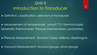
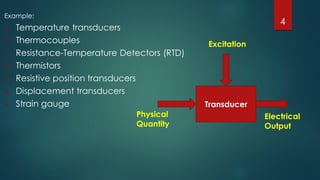
The document focuses on transducers, specifically discussing their definition, classification, and selection criteria, as well as various methods for measuring temperature and pressure, including resistance temperature detectors (RTDs) and thermocouples. It highlights the characteristics, advantages, and limitations of RTDs and compares them to thermocouples for industrial applications. Furthermore, the document elaborates on different types of RTDs and wiring configurations to enhance measurement accuracy.


![CLASSIFICATION OF TRANSDUCERS
A] Broadly classified in TWO groups;
1] Active Transducer or Self generating type transducer :- develop their own
voltage or current (e.g. Thermocouple and thrmopile , piezoelectric pick up ,
photovoltaic cell etc.)
2] Passive Transducers or Externally powered transducers :- derive power from
external source (e.g RTD , Thermistor, potentiometric devices etc)
5](https://image.slidesharecdn.com/introductiontotransducers-180303054442/85/Introduction-to-transducers-5-320.jpg)
![B] Based on type of output
1] Analog transducer:- convert i/p physical quantity into an analogous o/p which
is continuous function of time.
(e.g Strain guage , Thermocouple , Thermistor, LVDT etc)
2] Digital transducer :- convert i/p physical quantity into an electrical o/p which
may be in pulse form
6](https://image.slidesharecdn.com/introductiontotransducers-180303054442/85/Introduction-to-transducers-6-320.jpg)
![C] Based on Electrical principle involved
1.Variable-resistance type:
a. Strain and pressure gauges b. Thermistors, resistance thermometers c. Photoconductive cell
2.Variable –inductance type-
a. LVDT b. Reluctance pick up c. Eddy current gauge
3.Variable-capacitance type-
a. capacitor microphone b. Pressure gauge c. Dielectric gauge
4.Voltage generating type-
a. Thermocouple b. Photovoltaic cell c. Rotational motion tachometer d. Piezzoelectric pick up
5. Voltage divider type-
a. Potentiometer position sensor b. Pressure actuated voltage divider
7](https://image.slidesharecdn.com/introductiontotransducers-180303054442/85/Introduction-to-transducers-7-320.jpg)


![Temperature Relationships
(°F) = 9/5*(°C) +32
(°C) = 5/9*[(°F) –32]
(°F) = (°R) – 459.67
(°C) = (K) – 273.15
36](https://image.slidesharecdn.com/introductiontotransducers-180303054442/85/Introduction-to-transducers-36-320.jpg)


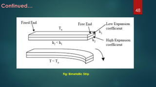

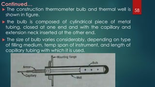
![Continued…
The radius of the curvature of the bimetallic strip which
was initially flat is determined using the following
relationship.
R= t{3(1+m)² + (1+m)[m²+1/m]}/6(άh-άl)(T2-T1)(1+m) ²
where,
R= radius of the curvature at the temperature T2.
t = total thickness of the bimetallic strip = (t1+t2)
m=t1/t2 = Thickness of lower – expansion metal/thickness of higher – expansion
metal.
άl= coefficient of expansion of lower expansion metal.
άh= coefficient of expansion of higher expansion metal.
T1 = Initial temperature ,
T2 =Final temperature.
50](https://image.slidesharecdn.com/introductiontotransducers-180303054442/85/Introduction-to-transducers-50-320.jpg)