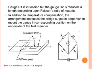
UNIT NO 3
Strain Gauges and Pressure
Measurement Devices
By:- Prof. P.B. Borakhede
CONTENTS
 Introduction
 Resistance Strain Gauge
a) Bonded Gauges
b) Unbonded Gauges
 Strain Gauge Circuits
a) Ballast Circuit
b) Wheatstone Bridge Circuit
 Temperature compensation
STRAIN GAUGES
Introduction
 A strain gauge is a strain transducer ie device for
measuring dimensional change or the surface of a
structural member under test.
 Measurement of strain is indispensable in a variety of
applications due to:
i) Utility of strain measurement as a means of
determining maximum stress values or to measure
force, pressure, acceleration, torque etc.
ii) Desirability to avoid the use of large factors of safety
in design of aircraft and automatic control equipment
due to mass/inertia considerations.
Prof. P.B. Borakhede, MGI-COET, Shegaon
Strain-measuring Techniques:
Prof. P.B. Borakhede, MGI-COET, Shegaon
Requirements of a strain gauge
Following points need consideration while designing any
strain gauge so that it gives an accurate measure of
strain:
• Extremely small size and negligible mass
• Simple and easy attachment to the specimen under test
• High sensitivity in the direction of measured strain but
low sensitivity in the transverse plane
• High speed of response: negligible time lag
• Capability to indicate static, transient and dynamic strain
• Insensitiveness to ambient conditions such as
temperature, humidity, vibration etc.
Prof. P.B. Borakhede, MGI-COET, Shegaon
Resistance strain gauge
Gauge Factor
 When a bar is subjected to a simple tensile loading,
there occurs an increase in length of the bar in the
direction of load.
 Strain refers to relative change in dimensions of bar
under load and it is the ratio of change in length to
original length of bar.
 Strain € = change in length/ original length =(∆l/l)
 Strain is usually dimensionless.
Consider a bar as shown in figure.
Prof. P.B. Borakhede, MGI-COET, Shegaon
An increase in length of the bar in the direction of applied
load is also accompanied by a decrease in lateral
dimension perpendicular to the load.
The ratio of strain in the lateral to lateral to in longitudinal is
called as Poisson’s Ratio.
Poissons Ratio (ũ) = (-∆D/D)/ ∆l/l
Consider appropriate length of a suitable material strained
within the elastic limits.
The change in physical dimension in conductor will cause a
change in its resistance.
The resistance of a conductor of length L, uniform cross-
section A and uniform resistivity ς is given by
R= (ςL/A)
Prof. P.B. Borakhede, MGI-COET, Shegaon
Where F represents fractional change in resistance
divided by a unit strain, and is called gauge factor.
The piezoelectric term is very small so it is neglected.
F= 1+ 2 ũ
Prof. P.B. Borakhede, MGI-COET, Shegaon
Classification of Resistance Strain gauge
Prof. P.B. Borakhede, MGI-COET, Shegaon
Unbonded Strain Gauges
 These gauges are not directly
bonded bonded onto the surface of specimen
 which is being examined.
 In this the fine wire filaments ie res
resistance wires are stretched around around
rigid and electrically insulated insulated pins on
two frames A & B.
which can move relative to each other.
The frames are held close with a spring loaded mechanism.
 When the force is applied on speciman the wires are
stretched.
 When the frame A moves relative to frame B, the wire
filaments are strained.
Prof. P.B. Borakhede, MGI-COET, Shegaon
 The strain can be detected through measurement of
change in resistance by electrical circuit.
 The range of unbonded strain gauge is 0.15% strain
with accuracy better than 0.1%.
 Since the gauges are not cemented but are simply
screwed at the desired location, they can be detached
and used again.
 These gauges are used mainly for measurement of
force, pressure, acceleration rather than for
measurement of displacement because of its massive
structure.
Prof. P.B. Borakhede, MGI-COET, Shegaon
Bonded Strain Gauges
 These gauges are bonded or cemented directly onto the
surface of the structural member which is being
examined.
Examples of bonded strain gauges are
i) Fine wire gauges cemented to a paper backing
ii) Metal foil gauges
iii) Semiconductor gauges
i) Wire type strain gauges
 A very fine wire of 0.025 mm in diameter is arranged in
the form of a grid shape consisting of a series of long
parallel loops onto the mechanical part on which
measurements are to be made.
Prof. P.B. Borakhede, MGI-COET, Shegaon
 Leads and connecting terminals are also provided for
electrically connecting the grid to the measurement
instrument.
 To ensure satisfactory performance, the bond between
the resistance element and the cement joining it to the
work piece should be stronger than grid itself.
 Further, for ease of handling, shipping, storing and
attaching to the specimen, the wire grid is first cemented
to a thin paper sheet or to a very thin bakelite sheet and
covered with a protective covering of paper, felt or thin
bakelite.
 The size of grid varies with application.
Prof. P.B. Borakhede, MGI-COET, Shegaon
ii) Metal Foil Gauge
 The gauge is produced by printed circuit technique and
consists of a foil grid on plastic backing.
 The desired grid pattern is first printed on a thin sheet
of metal-alloy foil with an acid resistant ink and then the
unprinted portion is etched away.
 This construction allows the use of varying sections
throughout the grid length.
 Larger area can be provided at the ends where lead
constructions are made.
 The gauge has been successfully employed to fillets
and sharply curved shapes because of its fine and
accurate construction.
Prof. P.B. Borakhede, MGI-COET, Shegaon
Advantages:
• Improved hysteresis
• Easy soldering of welding of leads
• Better fatigue life
• Very good lateral strain sensitivity
• Improved transmission of strain from the test surface to
the sensitive grid
• Stability at high temperature.
iii) Semiconductor or Piezoresistive Gauge:
 These gauges are produced in wafers from silicon of
germanium crystals in which exact amount of special
impurities such as boron have been added to impart
certain desirable characteristics.
Prof. P.B. Borakhede, MGI-COET, Shegaon
 The process is called doping and the crystals are known
as doped crystals.
 The semiconductor gauges are classified as
i) negative or n-type whose resistance decrease in
response to tensile strain
ii) Positive or p-type whose resistance increase in
response to tensile strain.
 The gauge is in the form of a single rectangular filament
about 0.05 mm thick by 0.25 mm wide and 1.5 and 12
mm in length.
Prof. P.B. Borakhede, MGI-COET, Shegaon
 A single film semiconductor gauge with leads on either
side is shown in figure.
 The semiconductor gauges are usually provided with a
plastic or stainless steel backing and are bonded to the
test surface by the same methods as wire and foil
gauges.
Advantages:
 Very high sensitive in comparison to metal gauges
 High gauge factor in range of 100 to 200.
 Low hysteresis
 Brittle and not suitable for large strain measurement
Prof. P.B. Borakhede, MGI-COET, Shegaon
Strain gauge Circuits
 In strain gauges, the change in resistance is very small.
Such small changes of resistance occurring in strain
measuring systems are converted into voltage and
generally measured by employing potentiometric circuit.
 The ballast circuit and Wheatstone bridge circuit .
1. Ballast circuit
Prof. P.B. Borakhede, MGI-COET, Shegaon
R= resistance of the unstrained resistance gauge
Rb= resistance of system outside transducer ( ballast
resistance)
Vs= supply voltage or input voltage.
Prof. P.B. Borakhede, MGI-COET, Shegaon
2. Wheatstone bridge Circuit
There are two ways of using wheatstone bridge circuit.
a) Balanced (null) condition
b) Unbalanced (deflection) condition
The null technique is more accurate by means of
resistance change but can only be used to measure
static strains.
a) Balanced condition
Prof. P.B. Borakhede, MGI-COET, Shegaon
 With no straining the resistances are so arranged that
potential at B equals to potential at D and galvanometer
gives zero deflection ie no current indication on
galvanometer.
Prof. P.B. Borakhede, MGI-COET, Shegaon
2. Deflection Mode
 In deflection mode initially bridge resistances are so
adjusted that the bridge is balanced. After gauges are
strained, the equilibrium gets disturbed.
 However, the bridge is allowed to stay unbalanced and
the galvanometer output Vo is observed.
Prof. P.B. Borakhede, MGI-COET, Shegaon
1. Quarter Bridge
 Only one strain gauge is used and the other three elements of
the bridge are fixed resistors.
Prof. P.B. Borakhede, MGI-COET, Shegaon
ii) Half Bridge Circuit
 Two of the bridge elements are strain gauges and the
other two are fixed resistors.
 The gauge R1 is bonded to upper surface of cantilever
beam, and second gauge R2 is bonded to the lower
surface and located underneath the first gauge.
 These gauges are connected electrically to form
adjacent limbs of the Wheatstone bridge circuit.
 When no strain is applied,
Vab = Vad= Vs/2
The terminals B and D are at same potential.
The bridge is then balanced and the output voltage
Vo= 0.
When load is applied to beam, resistance of gauge R1
increases due tensile load while R2 decreases due to
equal compressive strain.
Prof. P.B. Borakhede, MGI-COET, Shegaon
iii) Full Bridge Circuit
All the four elements of bridge are strain gauges.
When no strain applied,
Vab = Vad = Vs/2
Terminals B and D are at same potential. Bridge is
balanced and output voltage V0 = 0.
Prof. P.B. Borakhede, MGI-COET, Shegaon
dVo = dR/R = Vs F€
Temperature compensation of Strain Gauges
 Effect of ambient temperature variations on the strain
gauge output has to be removed or minimized.
 Because gauge resistance changes both with strain
and temperature.
 The temperature then considered as interfering input
and brings about a change in the gauge resistance in
two ways:
i) Resistance change in the wire filament or grid due to
change in its volume and resistivity,
ii) Resistance change due to differential expansion
Prof. P.B. Borakhede, MGI-COET, Shegaon
Existing between the gauge and test surface to which
gauge has been bonded.
Methods to compensate effect of temperature are:
1. Use of Dummy gauge:
Prof. P.B. Borakhede, MGI-COET, Shegaon
 Measuring gauge is active gauge, is mounted on the
test-piece and constitutes resistance R1 of bridge circuit.
 The gauge for temperature compensation called dummy
gauge, is connected to adjacent limb of bridge as
resistance R2.
 Dummy gauge is identical to active strain gauge so that
they form a match pair.
 Dummy gauge is bonded to separate, unstrained
component identical to that of loaded member.
 The dummy gauge remains unstrained throughout
process and suffers change in resistance due to
temperature only.
 Two gauges are placed close to each other so that they
are influnced equally by ambient temperature.
Prof. P.B. Borakhede, MGI-COET, Shegaon
 R1 and R2 are initially equal and with temperature
increase both the gauges will be subjected to equal
temperature induced strain.
Strain in active gauge= €d + €t
Strain in dummy gauge = €t
Total strain = €d+ €t- €t = €d
2. Temperature compensation by using compensating
gauge
Prof. P.B. Borakhede, MGI-COET, Shegaon
 In this the active gauge R1 is bonded to the top surface
and is in tension while compensating gauge R2 is
bonded to the bottom surface is in compression.
 Any change in temperature effects both the equally and
so no errors are caused by resistance change due to
temperature variation.
 Further, since the resistance changes due to applied
load are equal but of opposite sign in two gauges, the
arrangement has the added advantage in bridge output
being doubled.
3. Poission’s Method
 In the poission’s method, gauge R2 is bonded at right
angles to the active gauge R1 on the test specimen.
Prof. P.B. Borakhede, MGI-COET, Shegaon
 Gauge R1 is in tension but the gauge R2 is reduced in
length depending upon Poisson’s ratio of material.
 In addition to temperature compensation, the
arrangement increases the bridge output in proportion to
mount the gauge in corresponding position on the
underside of the test member.
Prof. P.B. Borakhede, MGI-COET, Shegaon
 Above considerations show that usually it is
advantageous to use more than one gauge in bridge
circuit for the following reasons:
i) To eliminate unwanted effects and to provide for
temperature compensation
ii) To increase the bridge output and thereby increase the
bridge sensitivity.
Prof. P.B. Borakhede, MGI-COET, Shegaon

Strain Gauges

  • 1.
    UNIT NO 3 StrainGauges and Pressure Measurement Devices By:- Prof. P.B. Borakhede
  • 2.
    CONTENTS  Introduction  ResistanceStrain Gauge a) Bonded Gauges b) Unbonded Gauges  Strain Gauge Circuits a) Ballast Circuit b) Wheatstone Bridge Circuit  Temperature compensation
  • 3.
    STRAIN GAUGES Introduction  Astrain gauge is a strain transducer ie device for measuring dimensional change or the surface of a structural member under test.  Measurement of strain is indispensable in a variety of applications due to: i) Utility of strain measurement as a means of determining maximum stress values or to measure force, pressure, acceleration, torque etc. ii) Desirability to avoid the use of large factors of safety in design of aircraft and automatic control equipment due to mass/inertia considerations. Prof. P.B. Borakhede, MGI-COET, Shegaon
  • 4.
    Strain-measuring Techniques: Prof. P.B.Borakhede, MGI-COET, Shegaon
  • 5.
    Requirements of astrain gauge Following points need consideration while designing any strain gauge so that it gives an accurate measure of strain: • Extremely small size and negligible mass • Simple and easy attachment to the specimen under test • High sensitivity in the direction of measured strain but low sensitivity in the transverse plane • High speed of response: negligible time lag • Capability to indicate static, transient and dynamic strain • Insensitiveness to ambient conditions such as temperature, humidity, vibration etc. Prof. P.B. Borakhede, MGI-COET, Shegaon
  • 6.
    Resistance strain gauge GaugeFactor  When a bar is subjected to a simple tensile loading, there occurs an increase in length of the bar in the direction of load.  Strain refers to relative change in dimensions of bar under load and it is the ratio of change in length to original length of bar.  Strain € = change in length/ original length =(∆l/l)  Strain is usually dimensionless. Consider a bar as shown in figure. Prof. P.B. Borakhede, MGI-COET, Shegaon
  • 7.
    An increase inlength of the bar in the direction of applied load is also accompanied by a decrease in lateral dimension perpendicular to the load. The ratio of strain in the lateral to lateral to in longitudinal is called as Poisson’s Ratio. Poissons Ratio (ũ) = (-∆D/D)/ ∆l/l Consider appropriate length of a suitable material strained within the elastic limits. The change in physical dimension in conductor will cause a change in its resistance. The resistance of a conductor of length L, uniform cross- section A and uniform resistivity ς is given by R= (ςL/A) Prof. P.B. Borakhede, MGI-COET, Shegaon
  • 8.
    Prof. P.B. Borakhede,MGI-COET, Shegaon
  • 9.
    Where F representsfractional change in resistance divided by a unit strain, and is called gauge factor. The piezoelectric term is very small so it is neglected. F= 1+ 2 ũ Prof. P.B. Borakhede, MGI-COET, Shegaon
  • 10.
    Classification of ResistanceStrain gauge Prof. P.B. Borakhede, MGI-COET, Shegaon
  • 11.
    Unbonded Strain Gauges These gauges are not directly bonded bonded onto the surface of specimen  which is being examined.  In this the fine wire filaments ie res resistance wires are stretched around around rigid and electrically insulated insulated pins on two frames A & B. which can move relative to each other. The frames are held close with a spring loaded mechanism.  When the force is applied on speciman the wires are stretched.  When the frame A moves relative to frame B, the wire filaments are strained. Prof. P.B. Borakhede, MGI-COET, Shegaon
  • 12.
     The straincan be detected through measurement of change in resistance by electrical circuit.  The range of unbonded strain gauge is 0.15% strain with accuracy better than 0.1%.  Since the gauges are not cemented but are simply screwed at the desired location, they can be detached and used again.  These gauges are used mainly for measurement of force, pressure, acceleration rather than for measurement of displacement because of its massive structure. Prof. P.B. Borakhede, MGI-COET, Shegaon
  • 13.
    Bonded Strain Gauges These gauges are bonded or cemented directly onto the surface of the structural member which is being examined. Examples of bonded strain gauges are i) Fine wire gauges cemented to a paper backing ii) Metal foil gauges iii) Semiconductor gauges i) Wire type strain gauges  A very fine wire of 0.025 mm in diameter is arranged in the form of a grid shape consisting of a series of long parallel loops onto the mechanical part on which measurements are to be made. Prof. P.B. Borakhede, MGI-COET, Shegaon
  • 14.
     Leads andconnecting terminals are also provided for electrically connecting the grid to the measurement instrument.  To ensure satisfactory performance, the bond between the resistance element and the cement joining it to the work piece should be stronger than grid itself.  Further, for ease of handling, shipping, storing and attaching to the specimen, the wire grid is first cemented to a thin paper sheet or to a very thin bakelite sheet and covered with a protective covering of paper, felt or thin bakelite.  The size of grid varies with application. Prof. P.B. Borakhede, MGI-COET, Shegaon
  • 15.
    ii) Metal FoilGauge  The gauge is produced by printed circuit technique and consists of a foil grid on plastic backing.  The desired grid pattern is first printed on a thin sheet of metal-alloy foil with an acid resistant ink and then the unprinted portion is etched away.  This construction allows the use of varying sections throughout the grid length.  Larger area can be provided at the ends where lead constructions are made.  The gauge has been successfully employed to fillets and sharply curved shapes because of its fine and accurate construction. Prof. P.B. Borakhede, MGI-COET, Shegaon
  • 16.
    Advantages: • Improved hysteresis •Easy soldering of welding of leads • Better fatigue life • Very good lateral strain sensitivity • Improved transmission of strain from the test surface to the sensitive grid • Stability at high temperature. iii) Semiconductor or Piezoresistive Gauge:  These gauges are produced in wafers from silicon of germanium crystals in which exact amount of special impurities such as boron have been added to impart certain desirable characteristics. Prof. P.B. Borakhede, MGI-COET, Shegaon
  • 17.
     The processis called doping and the crystals are known as doped crystals.  The semiconductor gauges are classified as i) negative or n-type whose resistance decrease in response to tensile strain ii) Positive or p-type whose resistance increase in response to tensile strain.  The gauge is in the form of a single rectangular filament about 0.05 mm thick by 0.25 mm wide and 1.5 and 12 mm in length. Prof. P.B. Borakhede, MGI-COET, Shegaon
  • 18.
     A singlefilm semiconductor gauge with leads on either side is shown in figure.  The semiconductor gauges are usually provided with a plastic or stainless steel backing and are bonded to the test surface by the same methods as wire and foil gauges. Advantages:  Very high sensitive in comparison to metal gauges  High gauge factor in range of 100 to 200.  Low hysteresis  Brittle and not suitable for large strain measurement Prof. P.B. Borakhede, MGI-COET, Shegaon
  • 19.
    Strain gauge Circuits In strain gauges, the change in resistance is very small. Such small changes of resistance occurring in strain measuring systems are converted into voltage and generally measured by employing potentiometric circuit.  The ballast circuit and Wheatstone bridge circuit . 1. Ballast circuit Prof. P.B. Borakhede, MGI-COET, Shegaon
  • 20.
    R= resistance ofthe unstrained resistance gauge Rb= resistance of system outside transducer ( ballast resistance) Vs= supply voltage or input voltage. Prof. P.B. Borakhede, MGI-COET, Shegaon
  • 21.
    Prof. P.B. Borakhede,MGI-COET, Shegaon
  • 22.
    Prof. P.B. Borakhede,MGI-COET, Shegaon
  • 23.
    2. Wheatstone bridgeCircuit There are two ways of using wheatstone bridge circuit. a) Balanced (null) condition b) Unbalanced (deflection) condition The null technique is more accurate by means of resistance change but can only be used to measure static strains. a) Balanced condition Prof. P.B. Borakhede, MGI-COET, Shegaon
  • 24.
     With nostraining the resistances are so arranged that potential at B equals to potential at D and galvanometer gives zero deflection ie no current indication on galvanometer. Prof. P.B. Borakhede, MGI-COET, Shegaon
  • 25.
    2. Deflection Mode In deflection mode initially bridge resistances are so adjusted that the bridge is balanced. After gauges are strained, the equilibrium gets disturbed.  However, the bridge is allowed to stay unbalanced and the galvanometer output Vo is observed. Prof. P.B. Borakhede, MGI-COET, Shegaon
  • 26.
    1. Quarter Bridge Only one strain gauge is used and the other three elements of the bridge are fixed resistors. Prof. P.B. Borakhede, MGI-COET, Shegaon
  • 27.
    Prof. P.B. Borakhede,MGI-COET, Shegaon
  • 28.
    ii) Half BridgeCircuit  Two of the bridge elements are strain gauges and the other two are fixed resistors.  The gauge R1 is bonded to upper surface of cantilever beam, and second gauge R2 is bonded to the lower surface and located underneath the first gauge.  These gauges are connected electrically to form adjacent limbs of the Wheatstone bridge circuit.  When no strain is applied, Vab = Vad= Vs/2 The terminals B and D are at same potential. The bridge is then balanced and the output voltage Vo= 0. When load is applied to beam, resistance of gauge R1 increases due tensile load while R2 decreases due to equal compressive strain. Prof. P.B. Borakhede, MGI-COET, Shegaon
  • 29.
    Prof. P.B. Borakhede,MGI-COET, Shegaon
  • 30.
    Prof. P.B. Borakhede,MGI-COET, Shegaon
  • 31.
    iii) Full BridgeCircuit All the four elements of bridge are strain gauges. When no strain applied, Vab = Vad = Vs/2 Terminals B and D are at same potential. Bridge is balanced and output voltage V0 = 0. Prof. P.B. Borakhede, MGI-COET, Shegaon
  • 32.
    Prof. P.B. Borakhede,MGI-COET, Shegaon
  • 33.
    dVo = dR/R= Vs F€ Temperature compensation of Strain Gauges  Effect of ambient temperature variations on the strain gauge output has to be removed or minimized.  Because gauge resistance changes both with strain and temperature.  The temperature then considered as interfering input and brings about a change in the gauge resistance in two ways: i) Resistance change in the wire filament or grid due to change in its volume and resistivity, ii) Resistance change due to differential expansion Prof. P.B. Borakhede, MGI-COET, Shegaon
  • 34.
    Existing between thegauge and test surface to which gauge has been bonded. Methods to compensate effect of temperature are: 1. Use of Dummy gauge: Prof. P.B. Borakhede, MGI-COET, Shegaon
  • 35.
     Measuring gaugeis active gauge, is mounted on the test-piece and constitutes resistance R1 of bridge circuit.  The gauge for temperature compensation called dummy gauge, is connected to adjacent limb of bridge as resistance R2.  Dummy gauge is identical to active strain gauge so that they form a match pair.  Dummy gauge is bonded to separate, unstrained component identical to that of loaded member.  The dummy gauge remains unstrained throughout process and suffers change in resistance due to temperature only.  Two gauges are placed close to each other so that they are influnced equally by ambient temperature. Prof. P.B. Borakhede, MGI-COET, Shegaon
  • 36.
     R1 andR2 are initially equal and with temperature increase both the gauges will be subjected to equal temperature induced strain. Strain in active gauge= €d + €t Strain in dummy gauge = €t Total strain = €d+ €t- €t = €d 2. Temperature compensation by using compensating gauge Prof. P.B. Borakhede, MGI-COET, Shegaon
  • 37.
     In thisthe active gauge R1 is bonded to the top surface and is in tension while compensating gauge R2 is bonded to the bottom surface is in compression.  Any change in temperature effects both the equally and so no errors are caused by resistance change due to temperature variation.  Further, since the resistance changes due to applied load are equal but of opposite sign in two gauges, the arrangement has the added advantage in bridge output being doubled. 3. Poission’s Method  In the poission’s method, gauge R2 is bonded at right angles to the active gauge R1 on the test specimen. Prof. P.B. Borakhede, MGI-COET, Shegaon
  • 38.
     Gauge R1is in tension but the gauge R2 is reduced in length depending upon Poisson’s ratio of material.  In addition to temperature compensation, the arrangement increases the bridge output in proportion to mount the gauge in corresponding position on the underside of the test member. Prof. P.B. Borakhede, MGI-COET, Shegaon
  • 39.
     Above considerationsshow that usually it is advantageous to use more than one gauge in bridge circuit for the following reasons: i) To eliminate unwanted effects and to provide for temperature compensation ii) To increase the bridge output and thereby increase the bridge sensitivity. Prof. P.B. Borakhede, MGI-COET, Shegaon