This document provides an introduction to sensors and transducers. It defines a sensor as a device that receives and responds to a signal or stimulus, and a transducer as a device that converts one form of energy into another. The document then discusses different types of sensors classified by their energy form, including displacement, force, pressure, velocity, and level sensors. It provides examples of common sensor types like potentiometers, strain gauges, LVDTs, optical encoders, and piezoelectric sensors. Finally, it covers the topic of signal conditioning, where the signal from the sensor is prepared for use in other parts of a system.
Introduction to sensors and transducers, explaining types, functions, and their roles. Key terms include signal, stimulus, sensors, actuators, and energy conversion.
Detailed classification of electronic sensor systems including active and passive sensors. Focus on energy conversion, output types, and common examples like thermocouples.
Key characteristics of sensors, including calibration, accuracy, hysteresis, resolution, and error types. Important for understanding sensor performance and reliability.
Various transducer classifications based on functions and principles. Discusses the selection criteria essential for accurate measurements and minimizing errors.
Definition and comparison of transducers, sensors, and actuators, highlighting their energy conversion roles in measurement and control systems.
Overview of different sensors related to displacement and position measurement, including potentiometers and their operation in the transformation of physical displacement.
In-depth explanation of strain gauges, their construction, operation, and the principle of measuring strain through resistance changes.
Functionality of LVDT as a positional sensor, including its construction, working principle, advantages, and practical applications in displacement measurement.
Functionality and types of optical encoders, detailing how mechanical position is translated into electrical signals, with distinction between absolute and incremental encoders.
Introduction of pneumatic sensors for measuring displacement using air pressure, and Hall effect sensors for magnetic field detection and applications.
Mechanism and application of tachogenerators as velocity sensors, describing how they function in converting motion into an electrical signal.
Working principles of pyroelectric sensors, detailing the behavior of temperature-dependent charge generation in response to infrared radiation.
Explanation of load cells as force sensors, detailing their structure, functionality, and conversion of mechanical load into electrical signals.
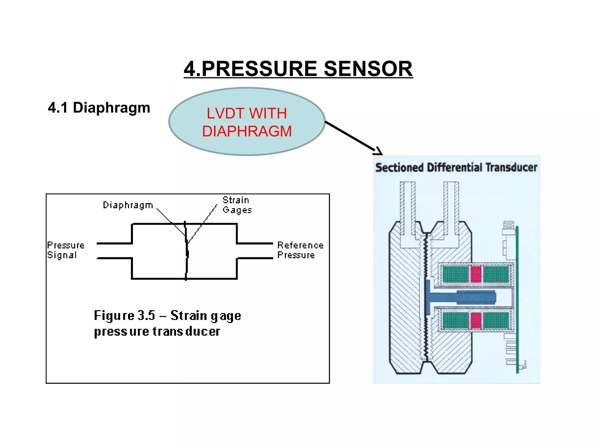
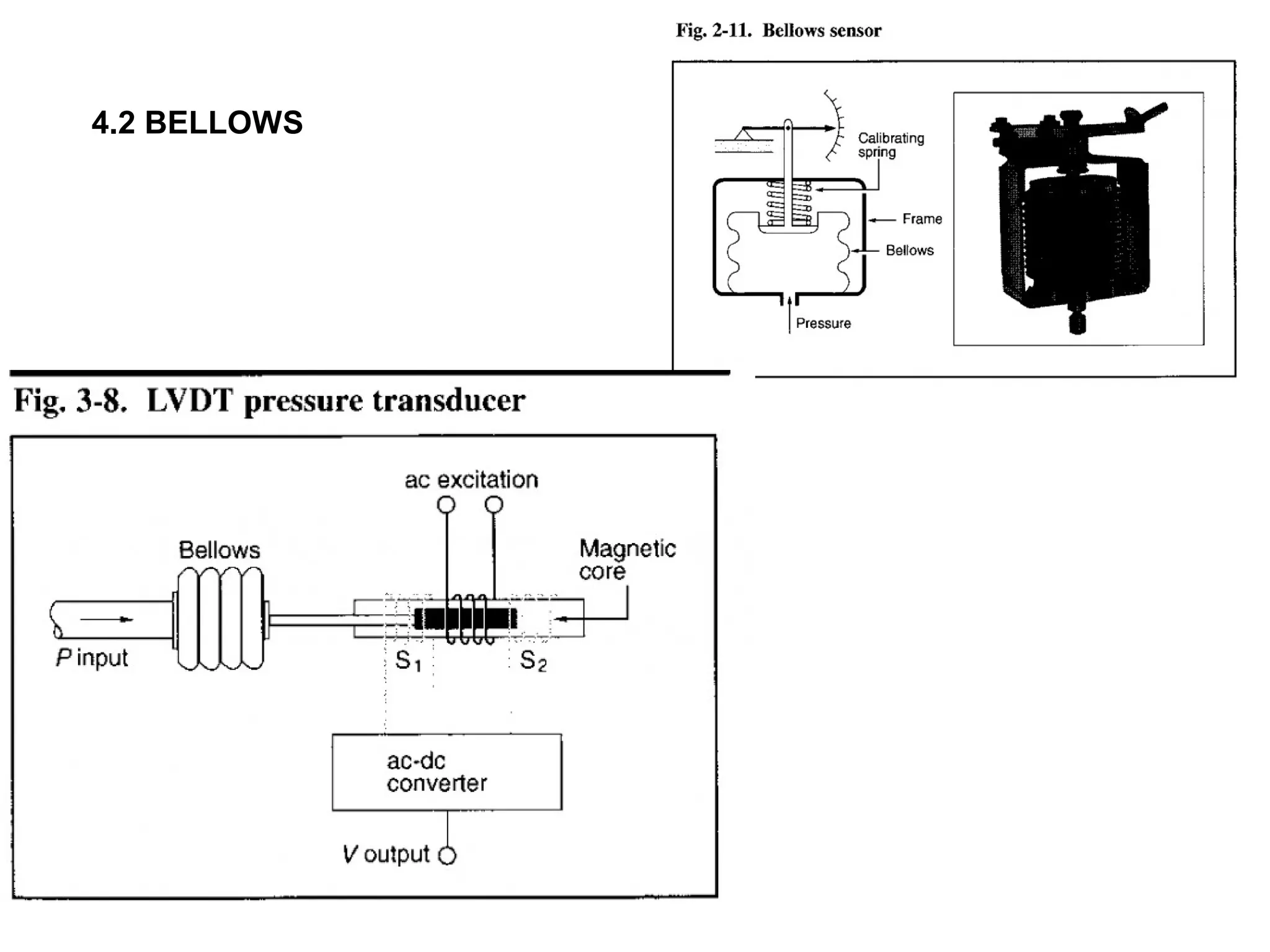
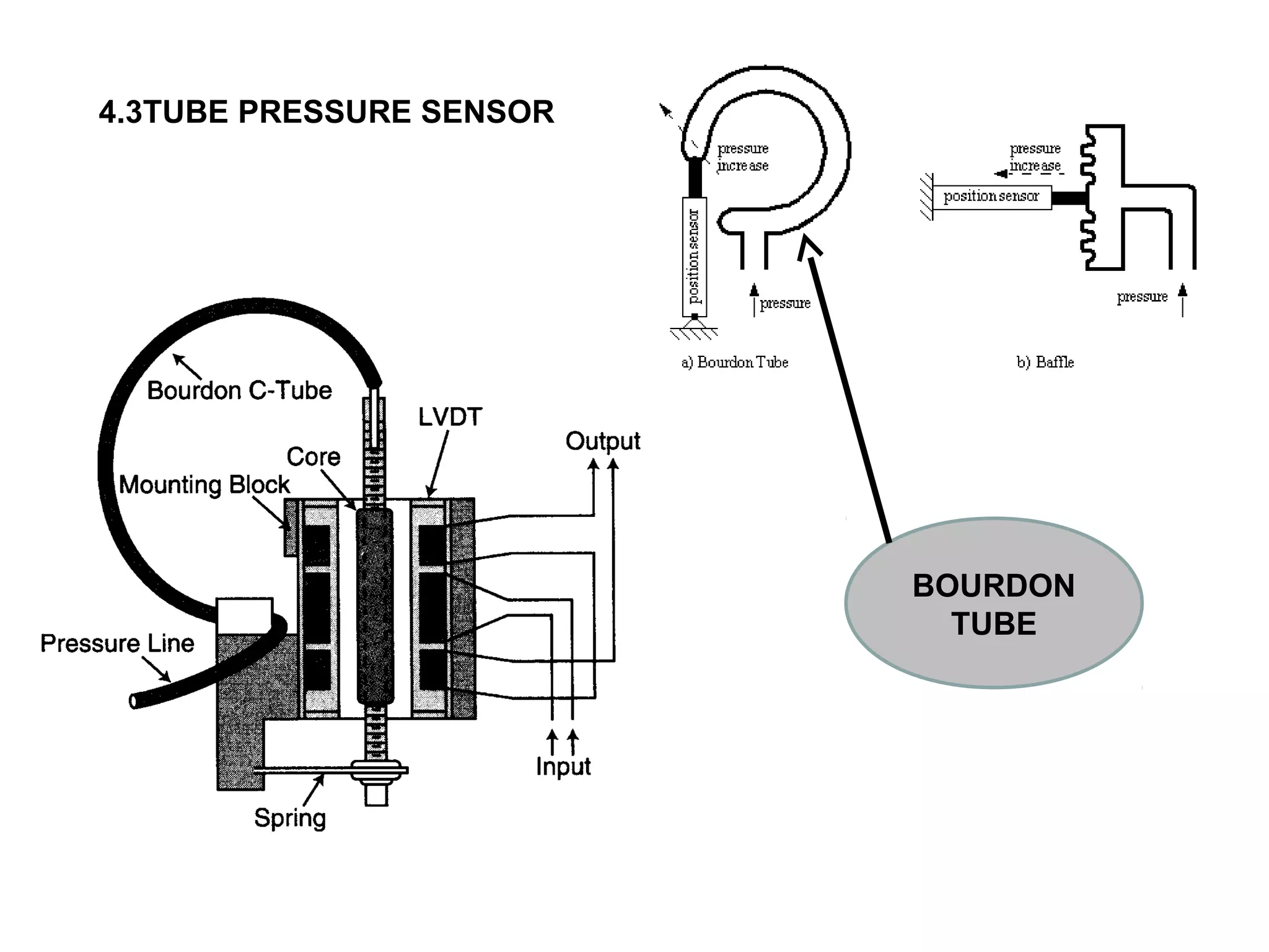
Various types of pressure sensors, including diaphragm LVDT and piezoelectric sensors, explaining their working principles and applications.
Overview of signal conditioning, including adjusting signal levels, filtering, and ensuring accuracy in data acquisition systems.
Definition and components of data acquisition systems, describing their role in measuring physical phenomena and converting signals for computer processing.
INTRODUCTION
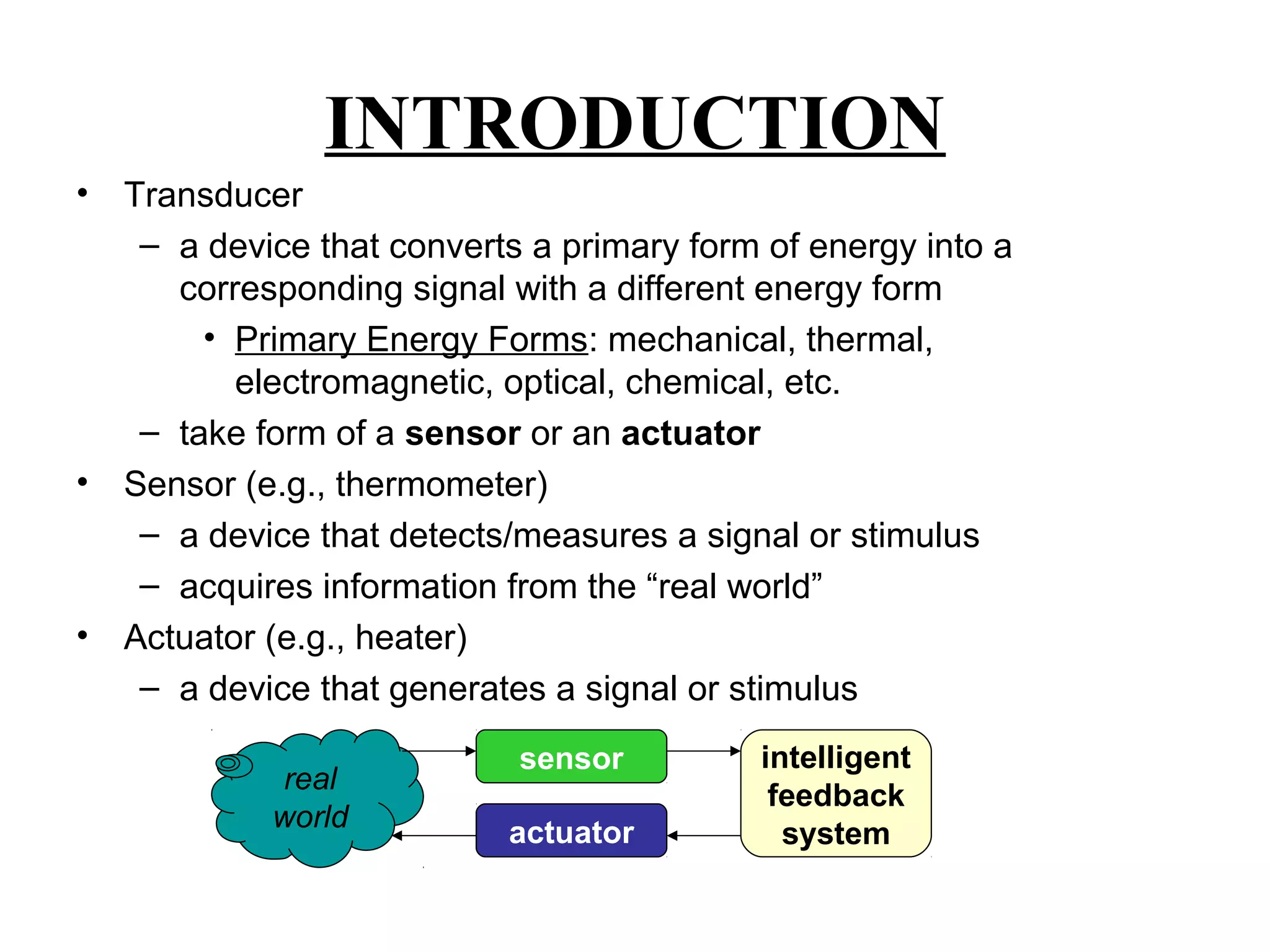
• Transducer
– adevice that converts a primary form of energy into a
corresponding signal with a different energy form
• Primary Energy Forms: mechanical, thermal,
electromagnetic, optical, chemical, etc.
– take form of a sensor or an actuator
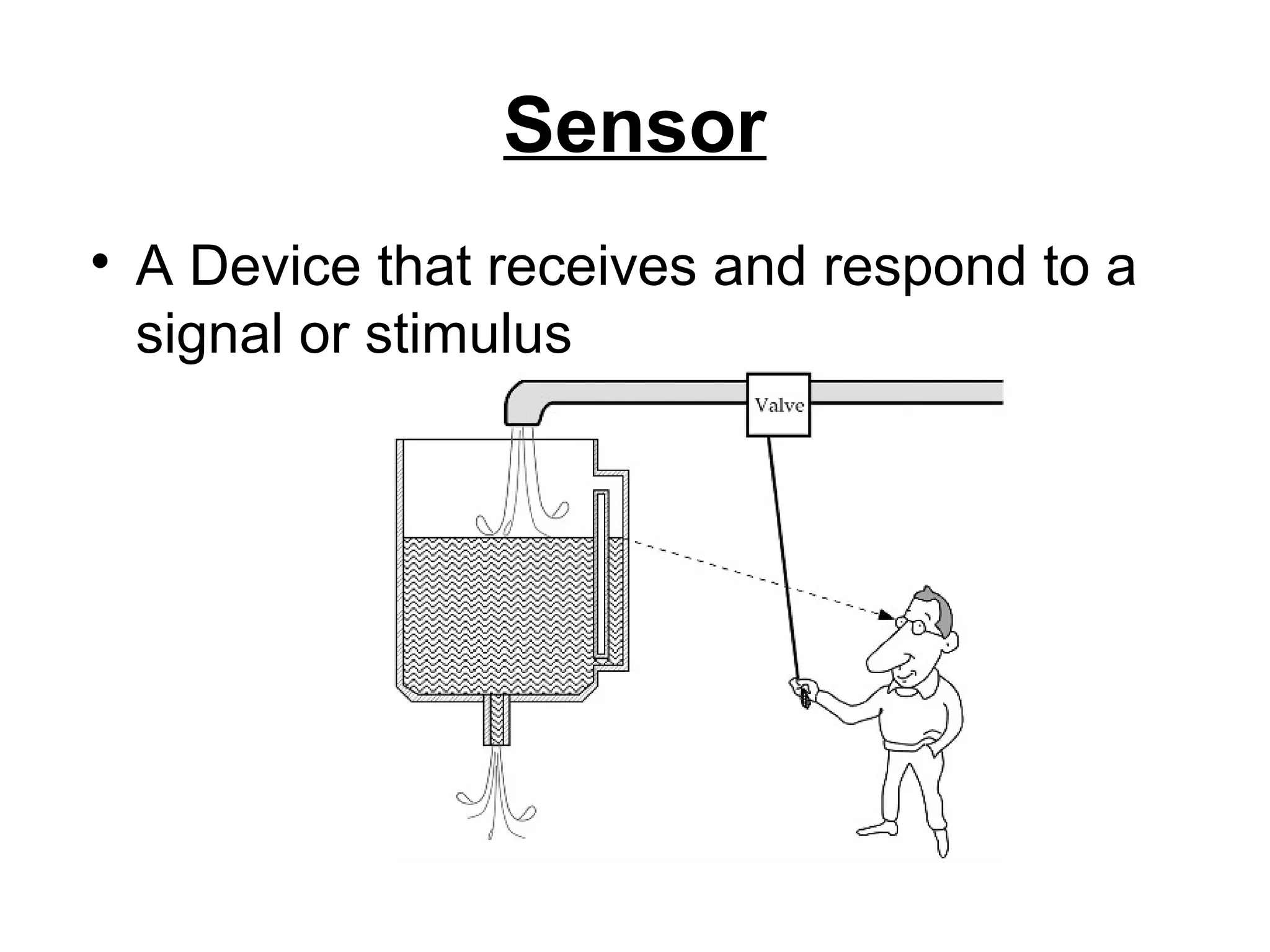
• Sensor (e.g., thermometer)
– a device that detects/measures a signal or stimulus
– acquires information from the “real world”
• Actuator (e.g., heater)
– a device that generates a signal or stimulus
real
world
sensor
actuator
intelligent
feedback
system
4.
usable
values
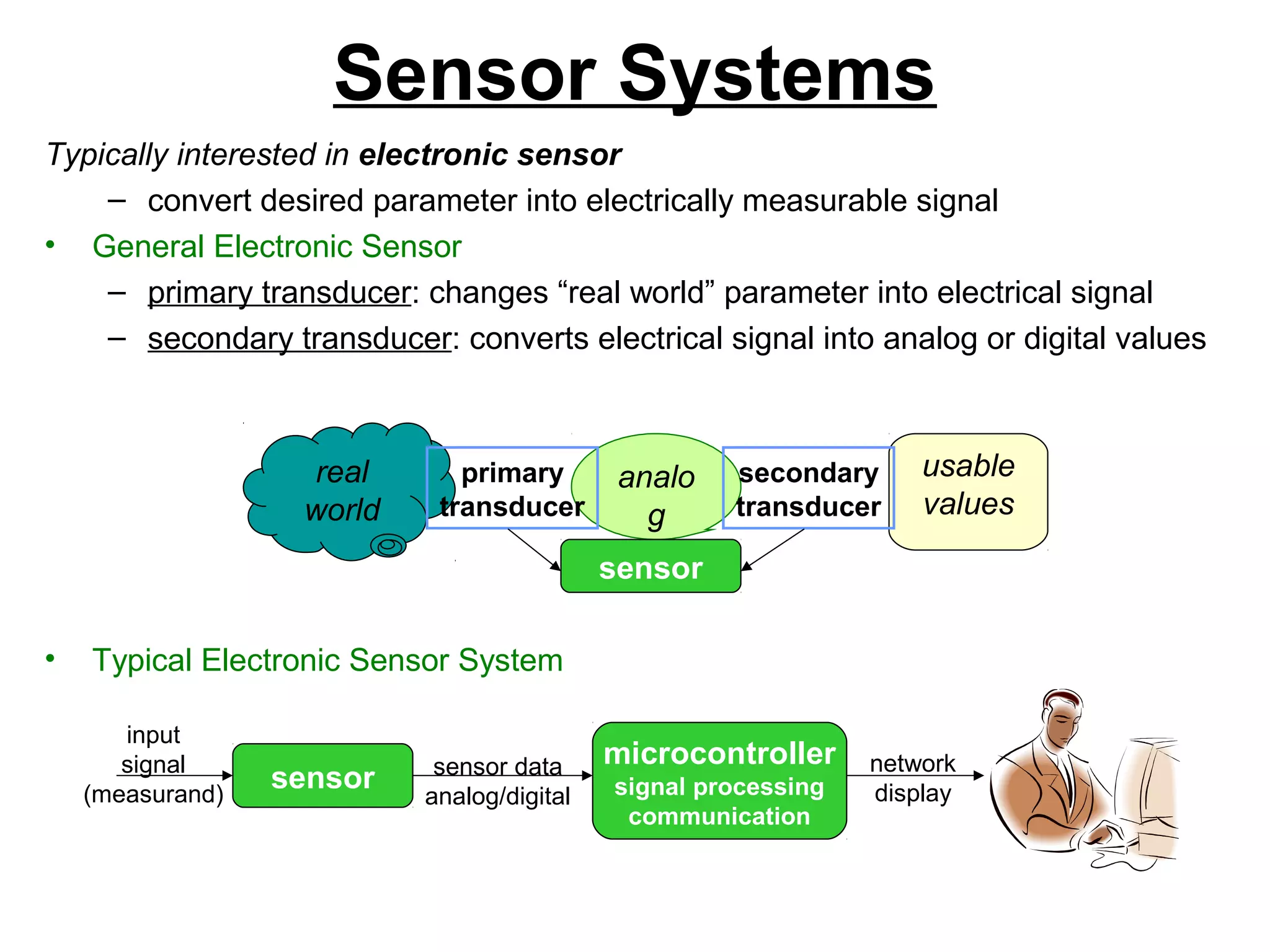
Sensor Systems
Typically interestedin electronic sensor
– convert desired parameter into electrically measurable signal
• General Electronic Sensor
– primary transducer: changes “real world” parameter into electrical signal
– secondary transducer: converts electrical signal into analog or digital values
• Typical Electronic Sensor System
real
world
analo
g
signal
primary
transducer
secondary
transducer
sensor
sensor
input
signal
(measurand)
microcontroller
signal processing
communication
sensor data
analog/digital
network
display
5.
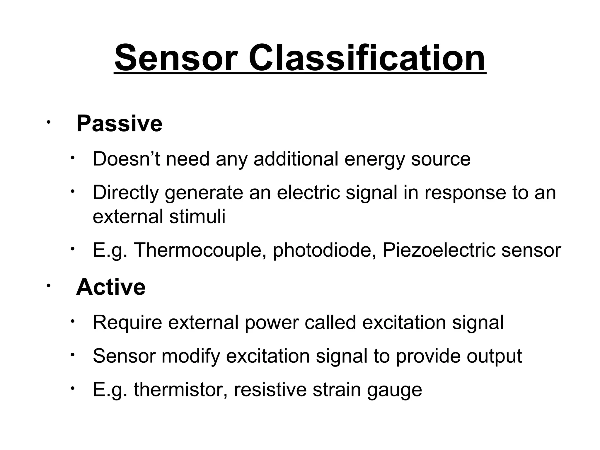
Sensor Classification
• Passive
•Doesn’t need any additional energy source
• Directly generate an electric signal in response to an
external stimuli
• E.g. Thermocouple, photodiode, Piezoelectric sensor
• Active
• Require external power called excitation signal
• Sensor modify excitation signal to provide output
• E.g. thermistor, resistive strain gauge
6.
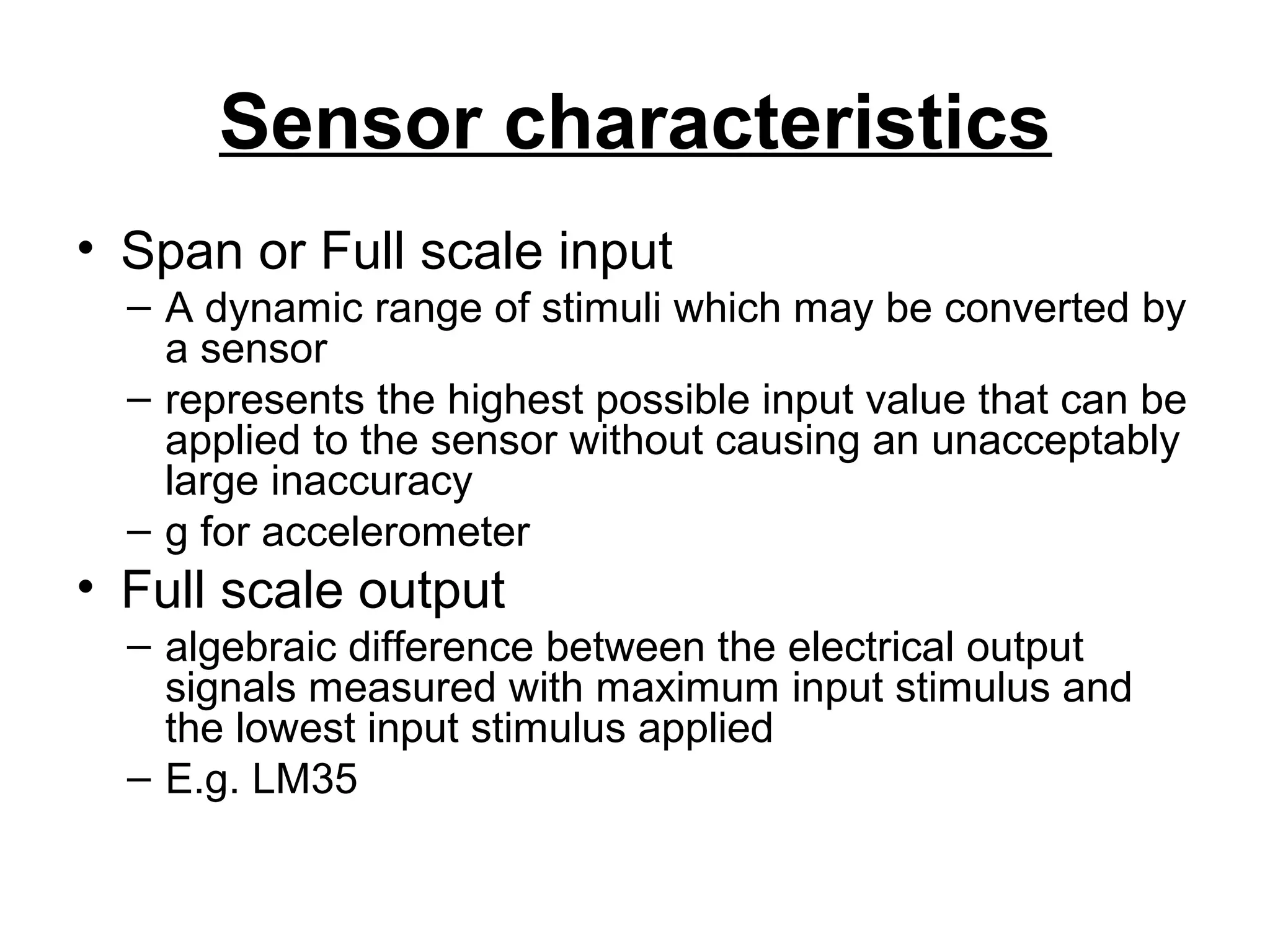
Sensor characteristics
• Spanor Full scale input
– A dynamic range of stimuli which may be converted by
a sensor
– represents the highest possible input value that can be
applied to the sensor without causing an unacceptably
large inaccuracy
– g for accelerometer
• Full scale output
– algebraic difference between the electrical output
signals measured with maximum input stimulus and
the lowest input stimulus applied
– E.g. LM35
7.
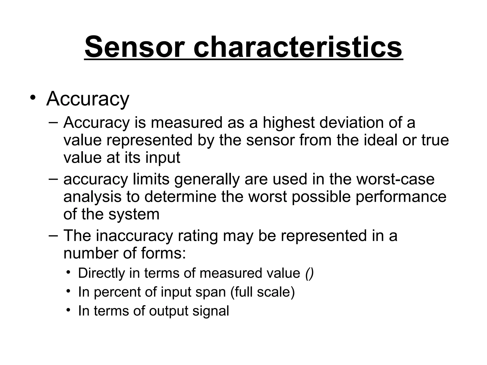
Sensor characteristics
• Accuracy
–Accuracy is measured as a highest deviation of a
value represented by the sensor from the ideal or true
value at its input
– accuracy limits generally are used in the worst-case
analysis to determine the worst possible performance
of the system
– The inaccuracy rating may be represented in a
number of forms:
• Directly in terms of measured value ()
• In percent of input span (full scale)
• In terms of output signal
8.
Sensor characteristics
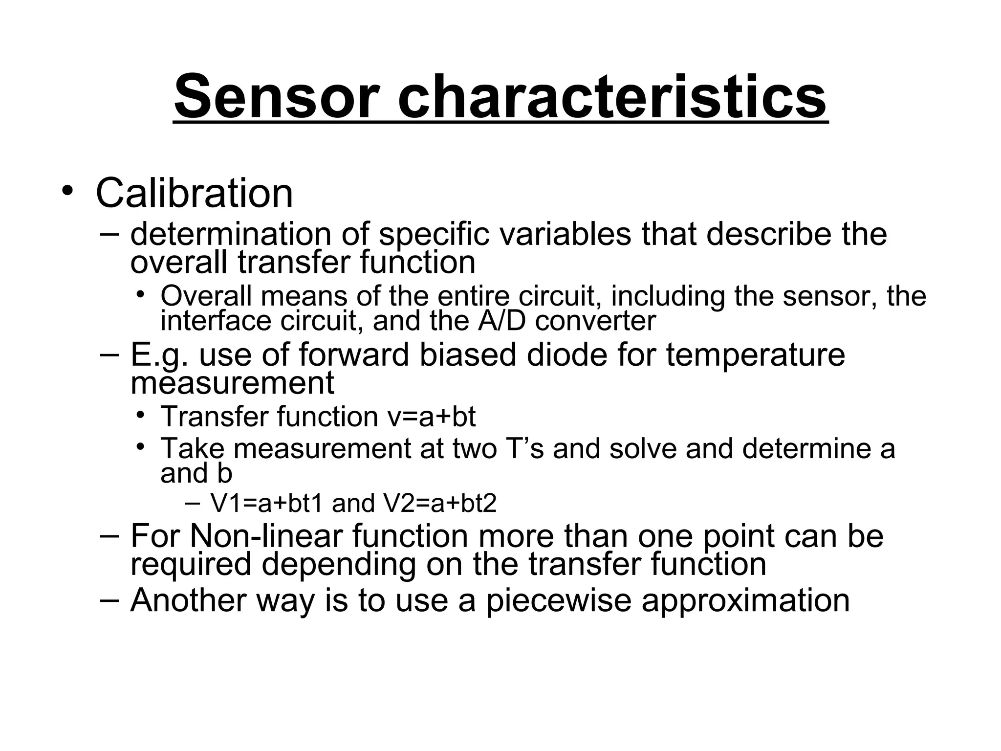
• Calibration
–determination of specific variables that describe the
overall transfer function
• Overall means of the entire circuit, including the sensor, the
interface circuit, and the A/D converter
– E.g. use of forward biased diode for temperature
measurement
• Transfer function v=a+bt
• Take measurement at two T’s and solve and determine a
and b
– V1=a+bt1 and V2=a+bt2
– For Non-linear function more than one point can be
required depending on the transfer function
– Another way is to use a piecewise approximation
9.
Sensor characteristics
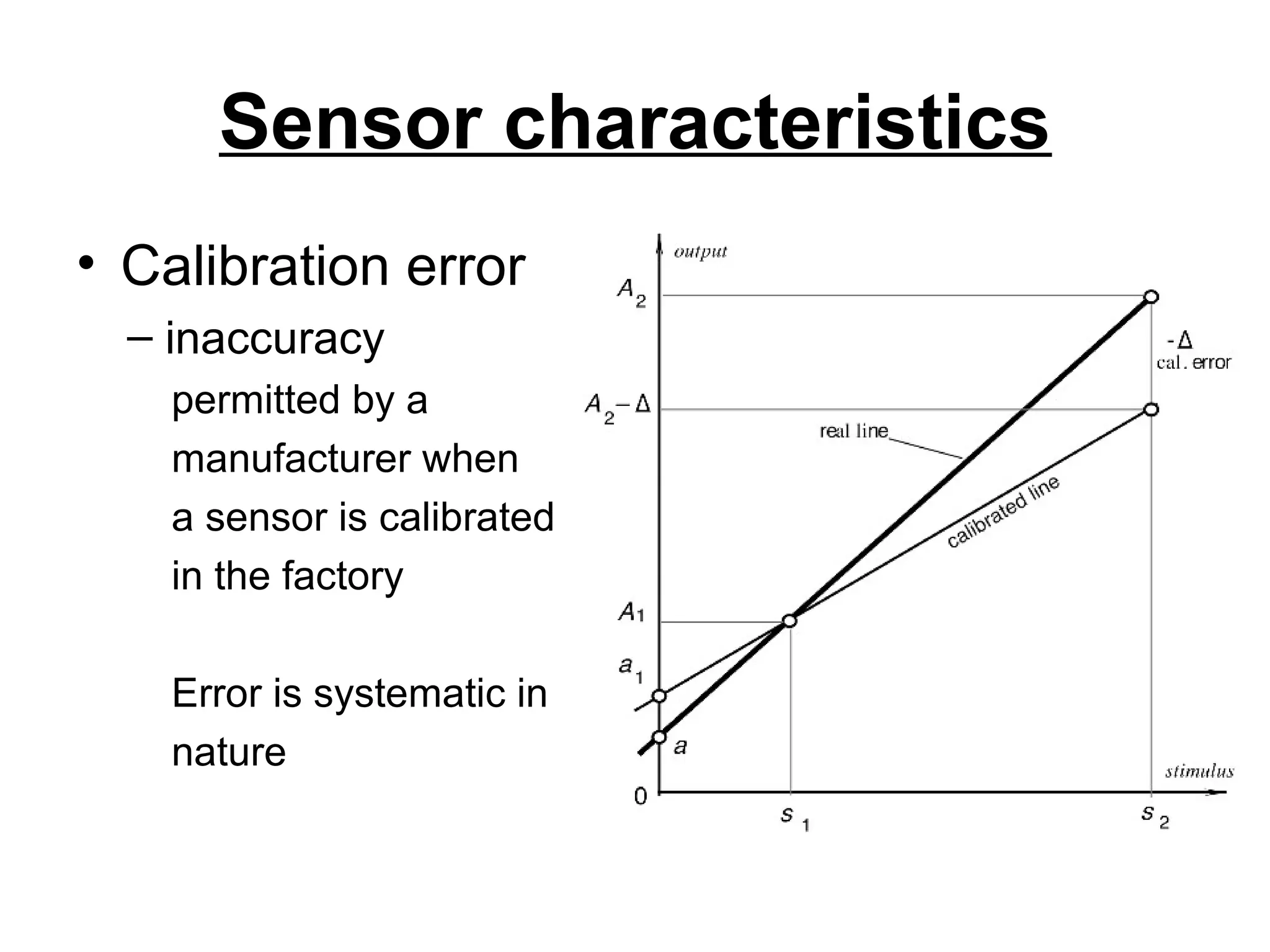
• Calibrationerror
– inaccuracy
permitted by a
manufacturer when
a sensor is calibrated
in the factory
Error is systematic in
nature
10.
Sensor characteristics
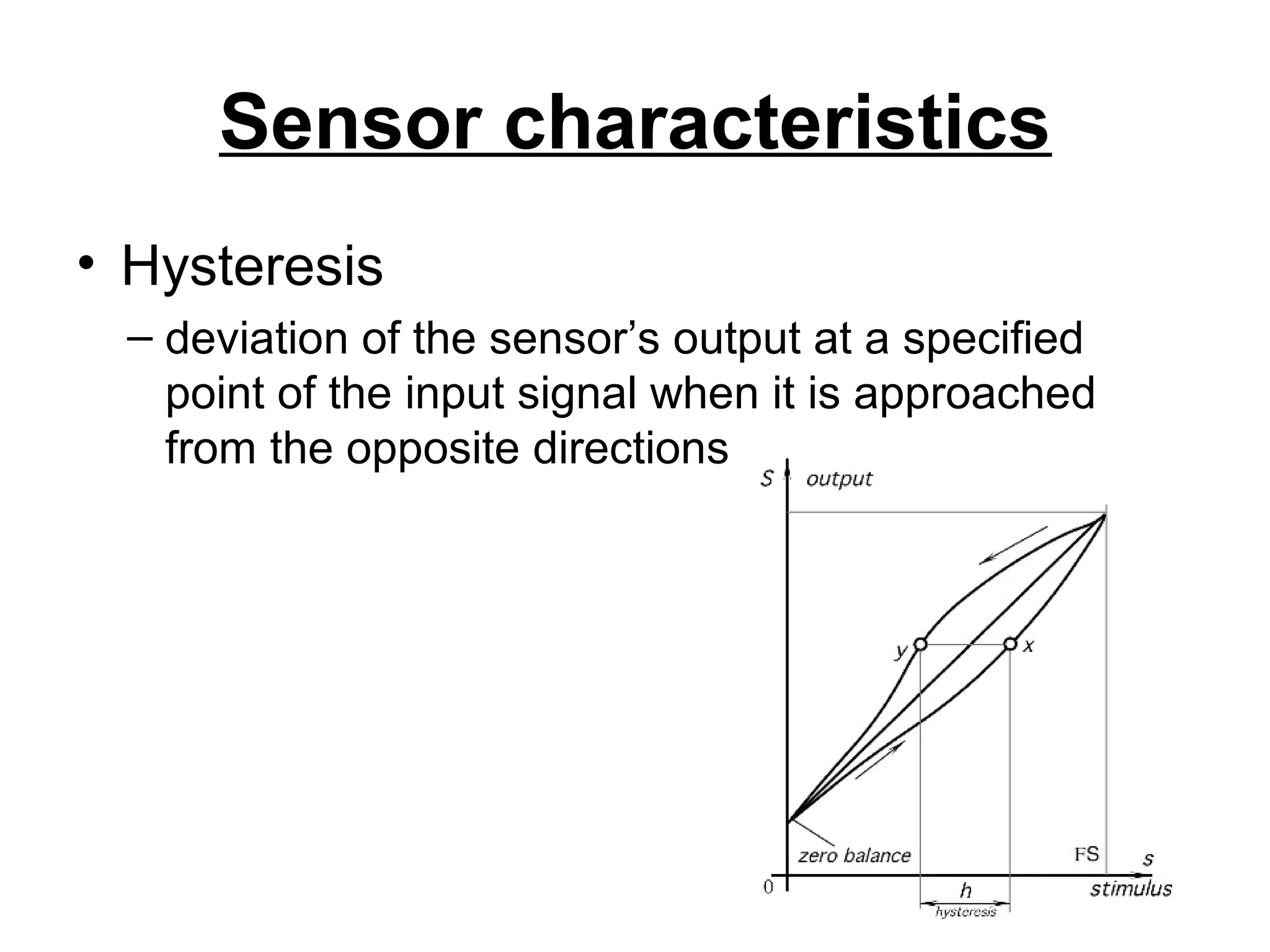
• Hysteresis
–deviation of the sensor’s output at a specified
point of the input signal when it is approached
from the opposite directions
Sensor characteristics
• Repeatability
–caused by the inability of a sensor to represent the
same value under identical conditions
– It is expressed as the maximum difference
between output readings as determined by two
calibrating cycles
– It is usually represented as % of FS
13.
Sensor characteristics
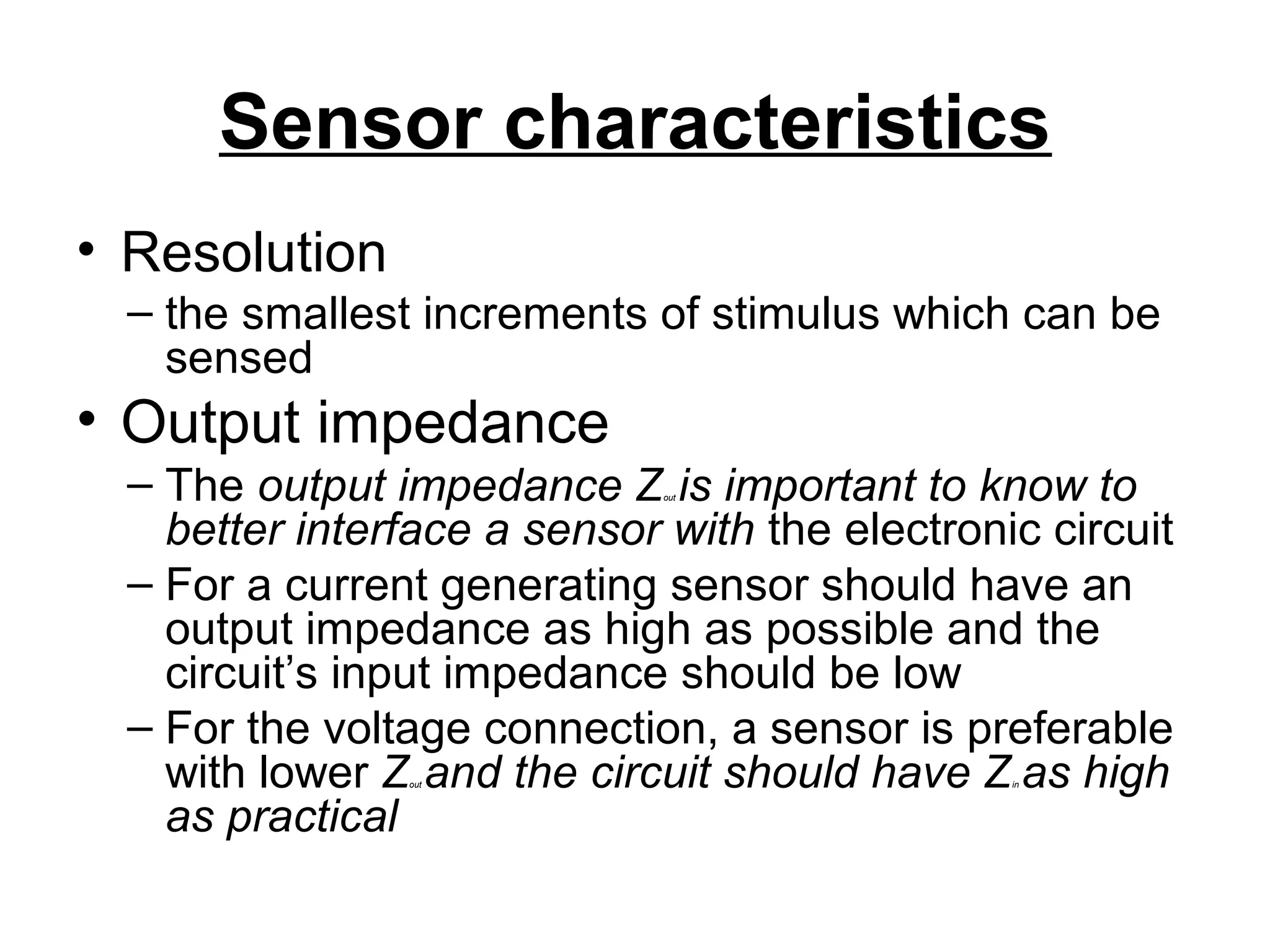
• Resolution
–the smallest increments of stimulus which can be
sensed
• Output impedance
– The output impedance Zout is important to know to
better interface a sensor with the electronic circuit
– For a current generating sensor should have an
output impedance as high as possible and the
circuit’s input impedance should be low
– For the voltage connection, a sensor is preferable
with lower Zout and the circuit should have Zin as high
as practical
14.
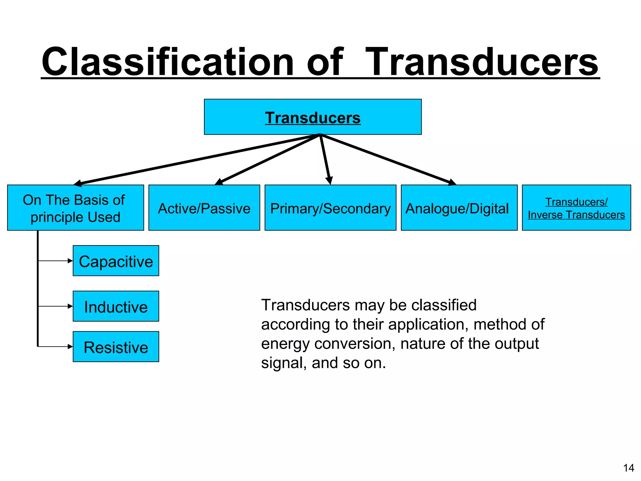
Classification of Transducers
Transducers
OnThe Basis of
principle Used
Active/Passive Primary/Secondary Analogue/Digital
Capacitive
Inductive
Resistive
Transducers/
Inverse Transducers
Transducers may be classified
according to their application, method of
energy conversion, nature of the output
signal, and so on.
14
15.
Selecting a Transducer
•What is the physical quantity to be measured?
• Which transducer principle can best be used to measure
this quantity?
• What accuracy is required for this measurement?
– Fundamental transducer parameters
– Physical conditions
– Environmental conditions
– Compatibility of the associated equipment
• Reducing the total measurement error :
– Using in-place system calibration with corrections performed in
the data reduction
– Artificially controlling the environment to minimize possible errors
15
16.
Transducer, Sensor, and
Actuator
•Transducer:
– a device that converts energy from one form to
another
• Sensor:
– converts a physical parameter to an electrical output
(a type of transducer, e.g. a microphone)
• Actuator:
• converts an electrical signal to a physical output
(opposite of a sensor, e.g. a speaker)
16
17.
1.DISPLACEMENT,POSITION &
PROXIMITY
• Displacementsensors are concerned with the
measurement of the amount by which some
object has been moved.
• Position sensors are concerned with the
determination of the position of some object in
relation to some reference point.
• Proximity sensors are a form of position sensor
and are used to determine when an object has
moved to within some particular critical distance
of the sensor. They are essentially devices
which give on/off outputs.
18.
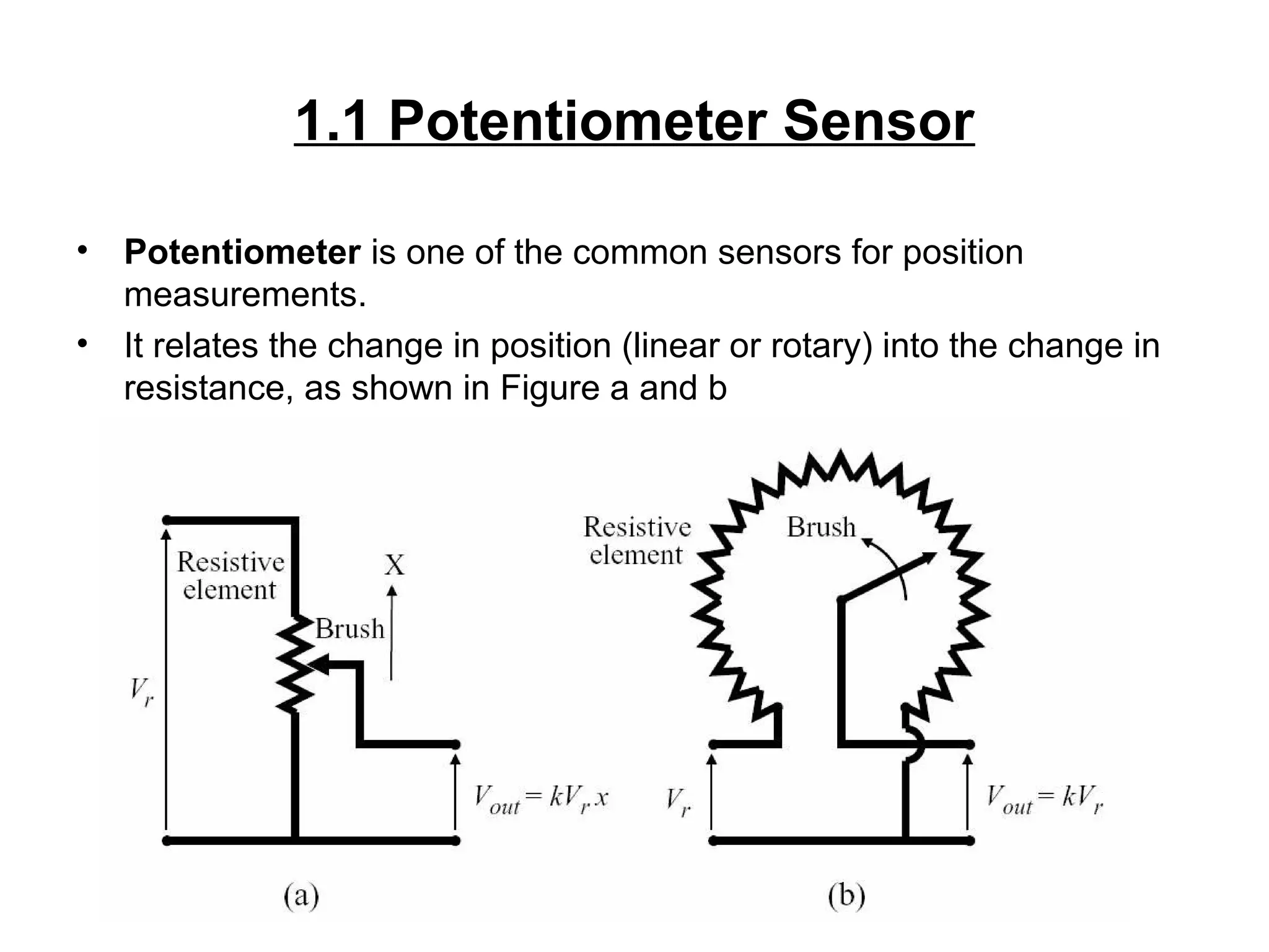
1.1 Potentiometer Sensor
•Potentiometer is one of the common sensors for position
measurements.
• It relates the change in position (linear or rotary) into the change in
resistance, as shown in Figure a and b
19.
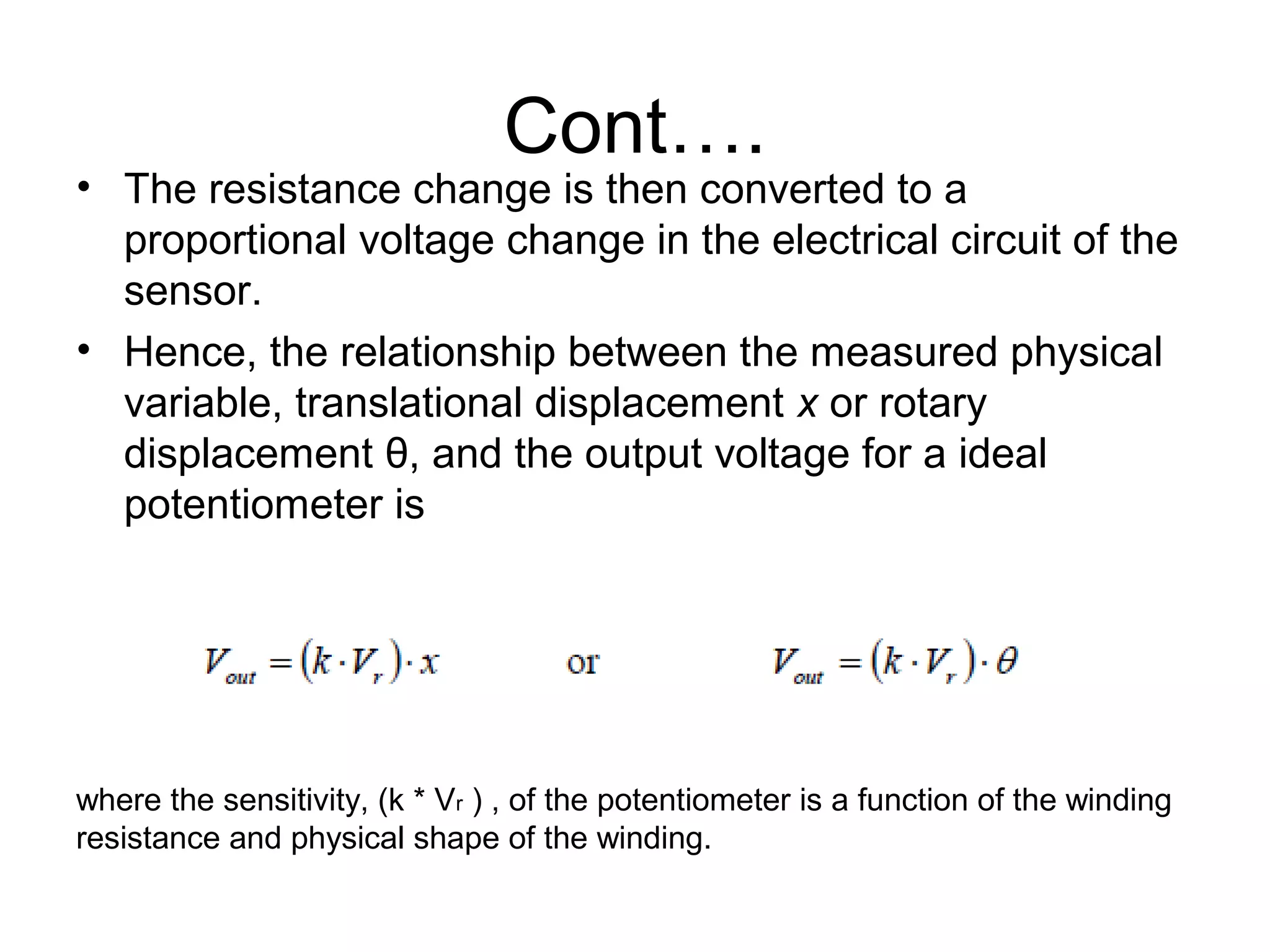
Cont….
• The resistancechange is then converted to a
proportional voltage change in the electrical circuit of the
sensor.
• Hence, the relationship between the measured physical
variable, translational displacement x or rotary
displacement θ, and the output voltage for a ideal
potentiometer is
where the sensitivity, (k * Vr ) , of the potentiometer is a function of the winding
resistance and physical shape of the winding.
1.2 Strain Gauge
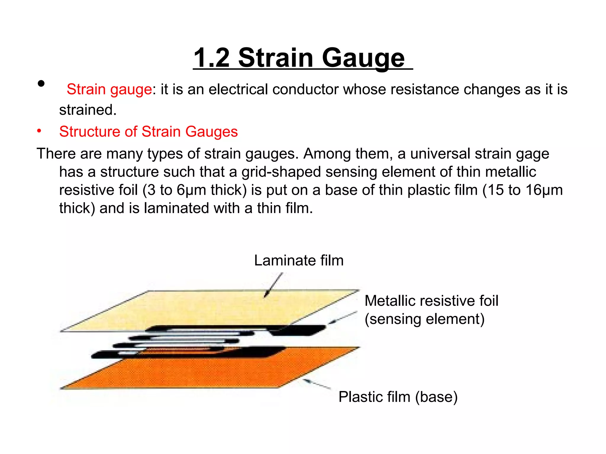
•Strain gauge: it is an electrical conductor whose resistance changes as it is
strained.
• Structure of Strain Gauges
There are many types of strain gauges. Among them, a universal strain gage
has a structure such that a grid-shaped sensing element of thin metallic
resistive foil (3 to 6μm thick) is put on a base of thin plastic film (15 to 16μm
thick) and is laminated with a thin film.
Plastic film (base)
Metallic resistive foil
(sensing element)
Laminate film
22.
Cont.…• Principle ofStrain Gages
• The strain gage is tightly bonded to a measuring object so that the sensing
element (metallic resistive foil) may elongate or contract according to the
strain borne by the measuring object.
• When bearing mechanical elongation or contraction, most metals undergo a
change in electric resistance.
• The strain gage applies this principle to strain measurement through the
resistance change. Generally, the sensing element of the strain gage is
made of a copper-nickel alloy foil.
• The alloy foil has a rate of resist-ance change proportional to strain with a
certain constant.
Let’s express the principle as follows:
ΔR = K.ε
R
where, R: Original resistance of strain gage, Ω (ohm)
ΔR: Elongation- or contraction-initiated resistance change, Ω (ohm)
K: Proportional constant (called gage factor)
ε: Strain
23.
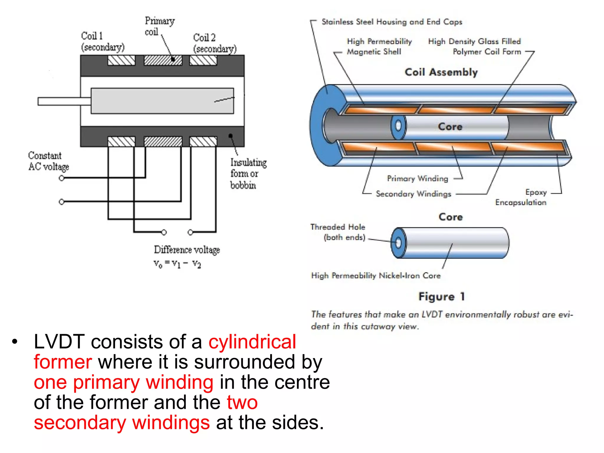
1.3Linear Variable DifferentialTransformer
(LVDT)
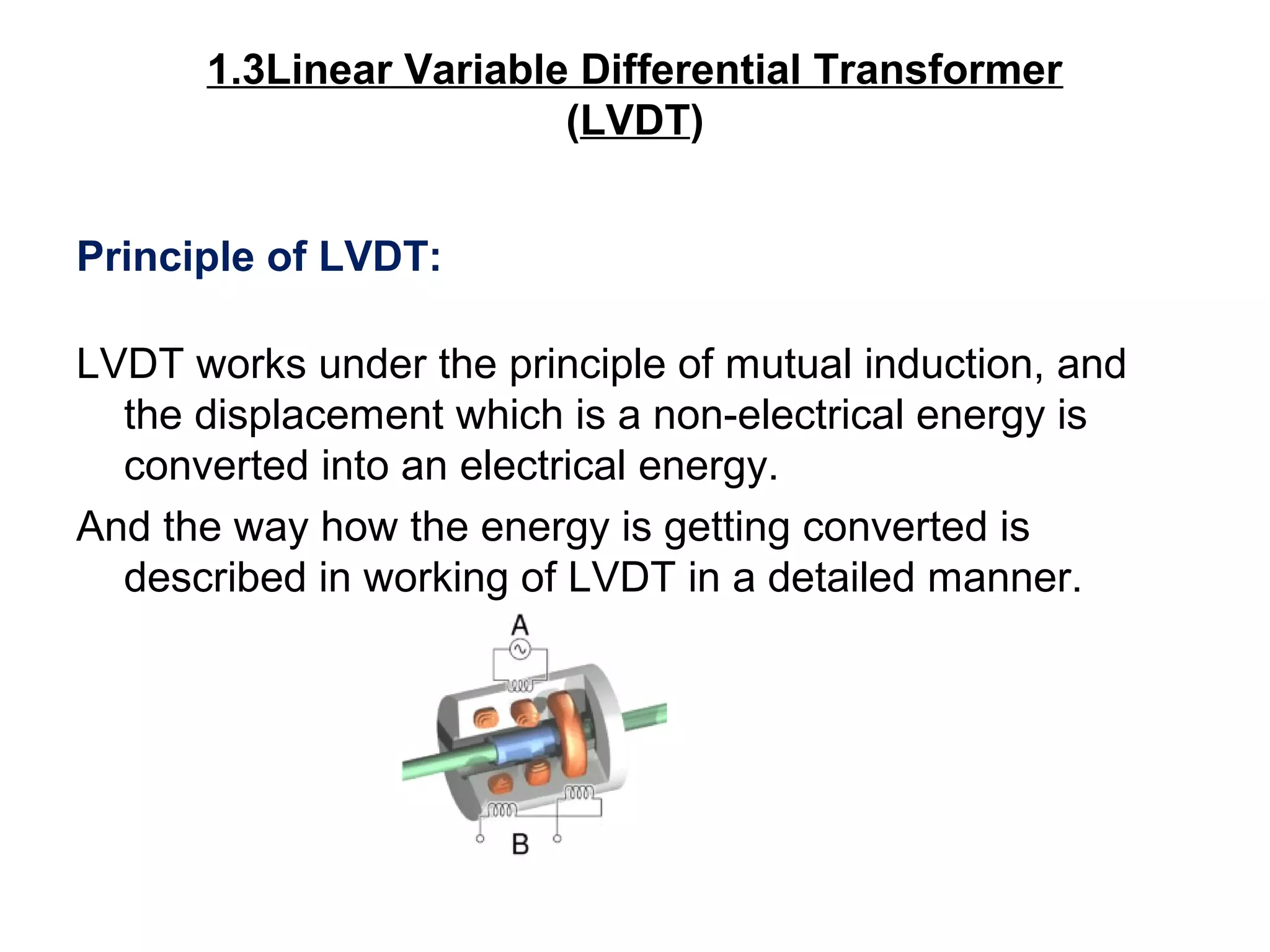
Principle of LVDT:
LVDT works under the principle of mutual induction, and
the displacement which is a non-electrical energy is
converted into an electrical energy.
And the way how the energy is getting converted is
described in working of LVDT in a detailed manner.
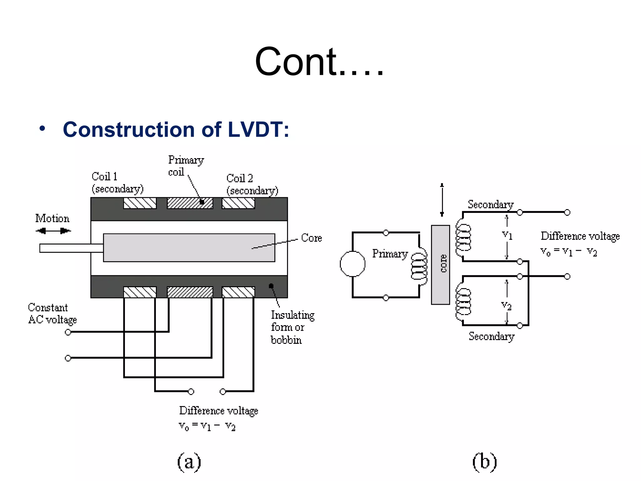
• LVDT consistsof a cylindrical
former where it is surrounded by
one primary winding in the centre
of the former and the two
secondary windings at the sides.
26.
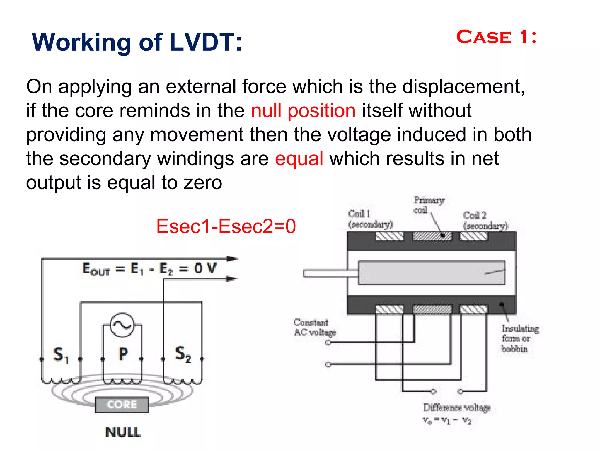
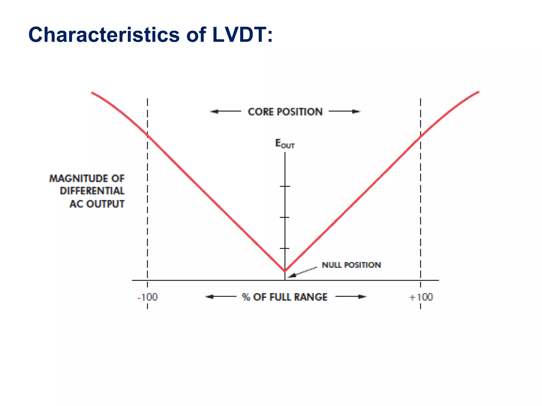
Working of LVDT:Case 1:
On applying an external force which is the displacement,
if the core reminds in the null position itself without
providing any movement then the voltage induced in both
the secondary windings are equal which results in net
output is equal to zero
Esec1-Esec2=0
27.
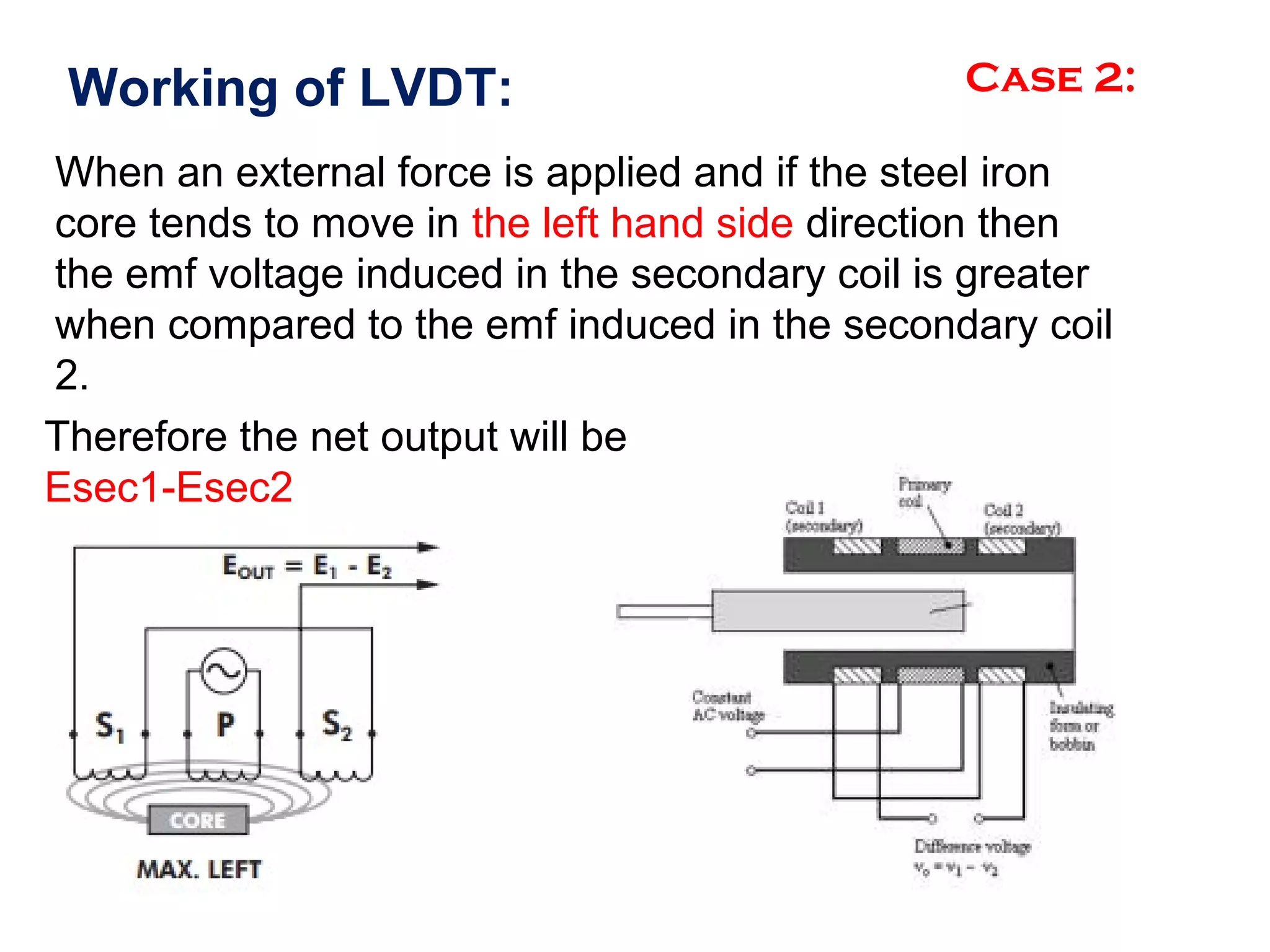
Working of LVDT:Case 2:
When an external force is applied and if the steel iron
core tends to move in the left hand side direction then
the emf voltage induced in the secondary coil is greater
when compared to the emf induced in the secondary coil
2.
Therefore the net output will be
Esec1-Esec2
28.
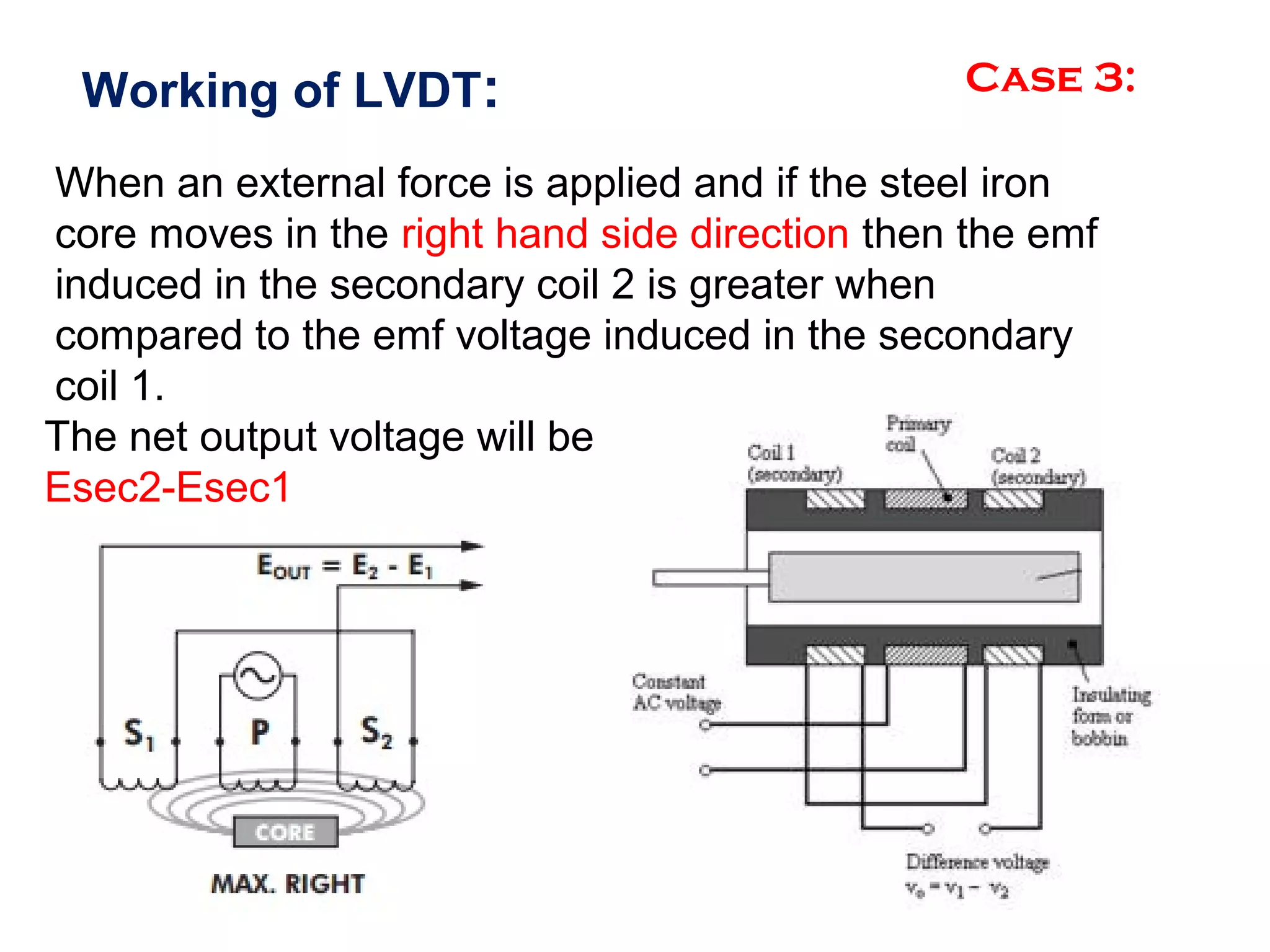
Working of LVDT:Case 3:
When an external force is applied and if the steel iron
core moves in the right hand side direction then the emf
induced in the secondary coil 2 is greater when
compared to the emf voltage induced in the secondary
coil 1.
The net output voltage will be
Esec2-Esec1
29.
Advantages of LVDT:
1)Infiniteresolution is present in LVDT
2)High output
3)LVDT gives High sensitivity
4)Very good linearity
5)Ruggedness
6)LVDT Provides Less friction
7)Low hysteresis
8)LVDT gives Low power consumption.
30.
Applications of LVDT:
1)LVDTis used to measure displacement ranging from fraction
millimeter to centimeter.
2)Acting as a secondary transducer, LVDT can be used as a device
to measure force, weight and pressure, etc..
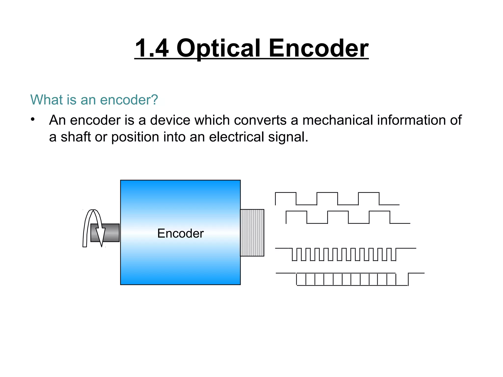
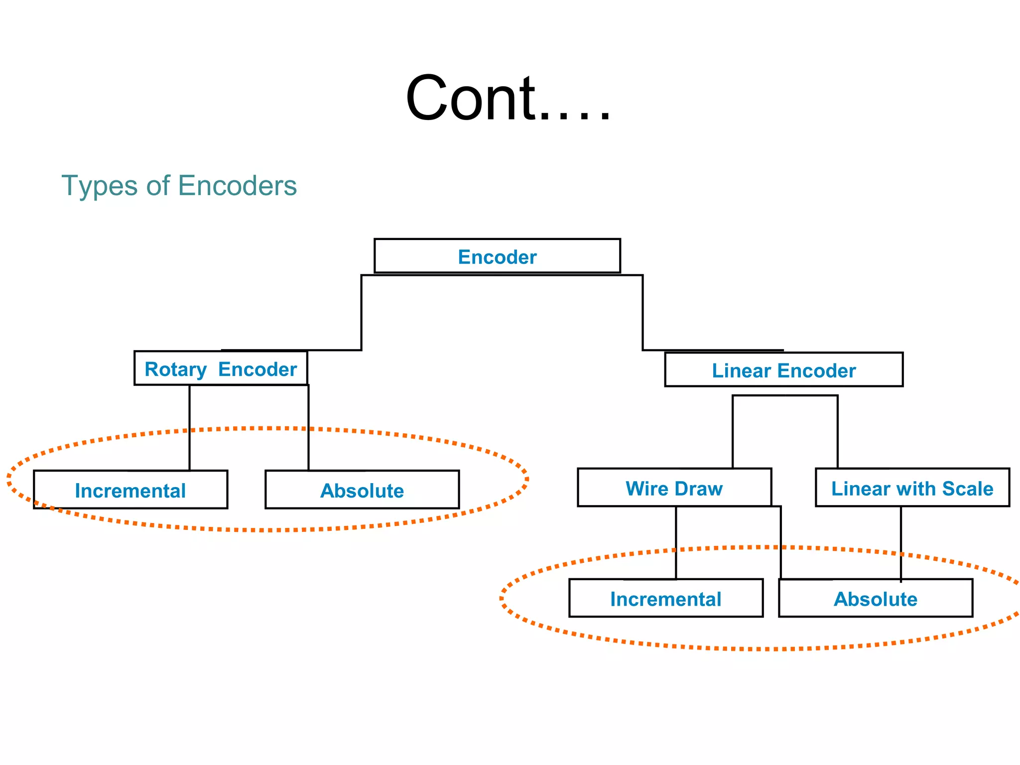
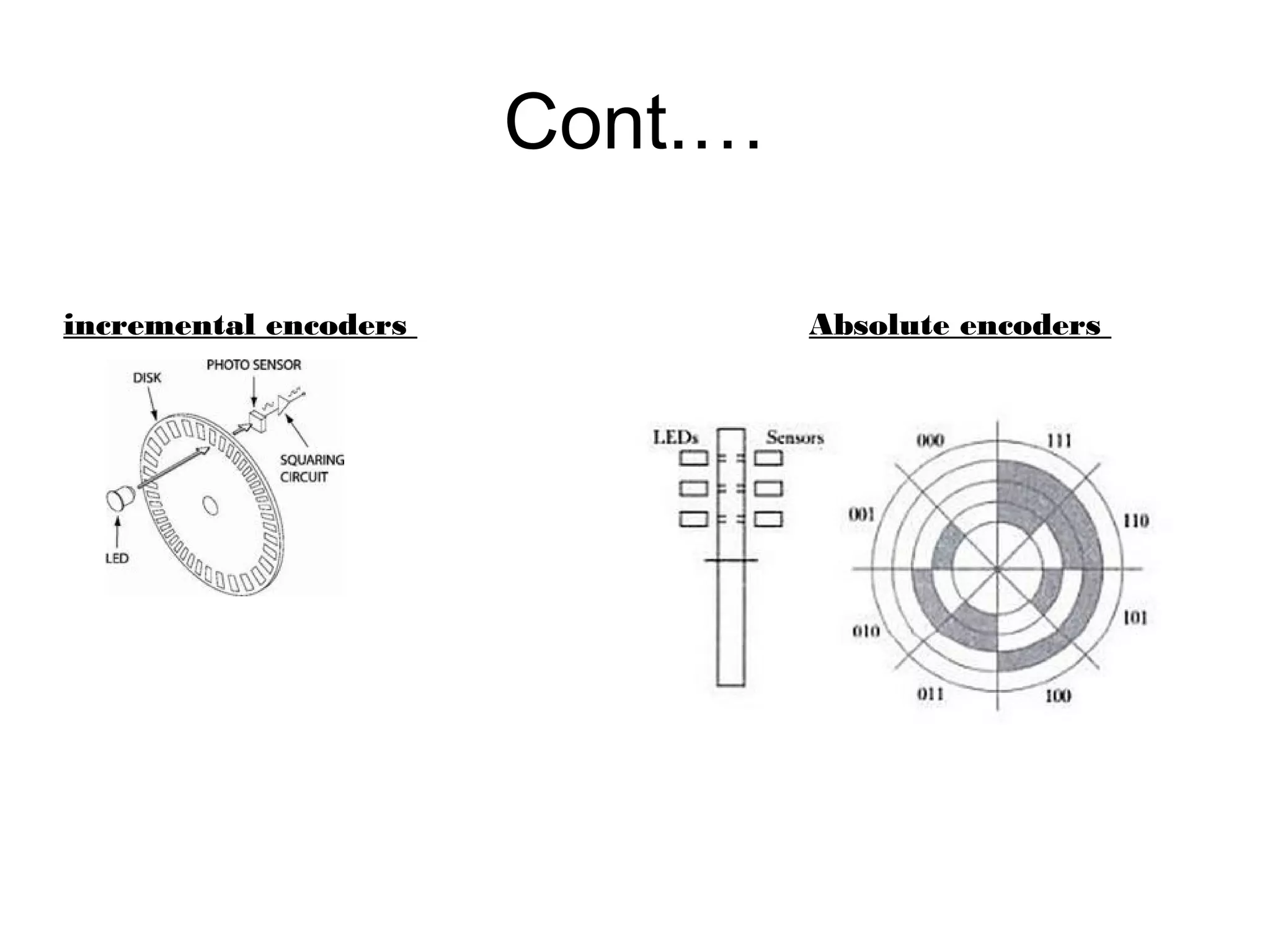
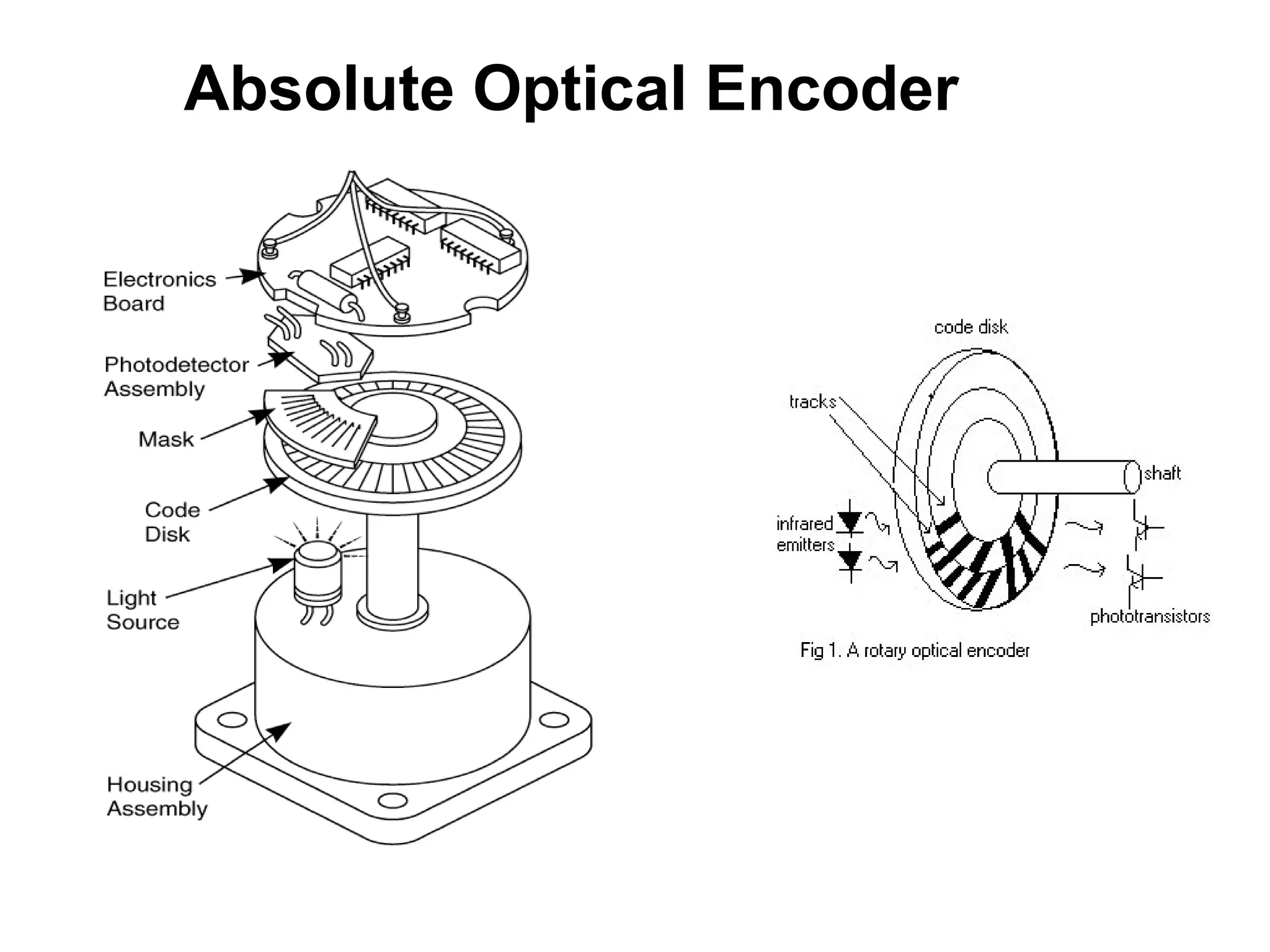
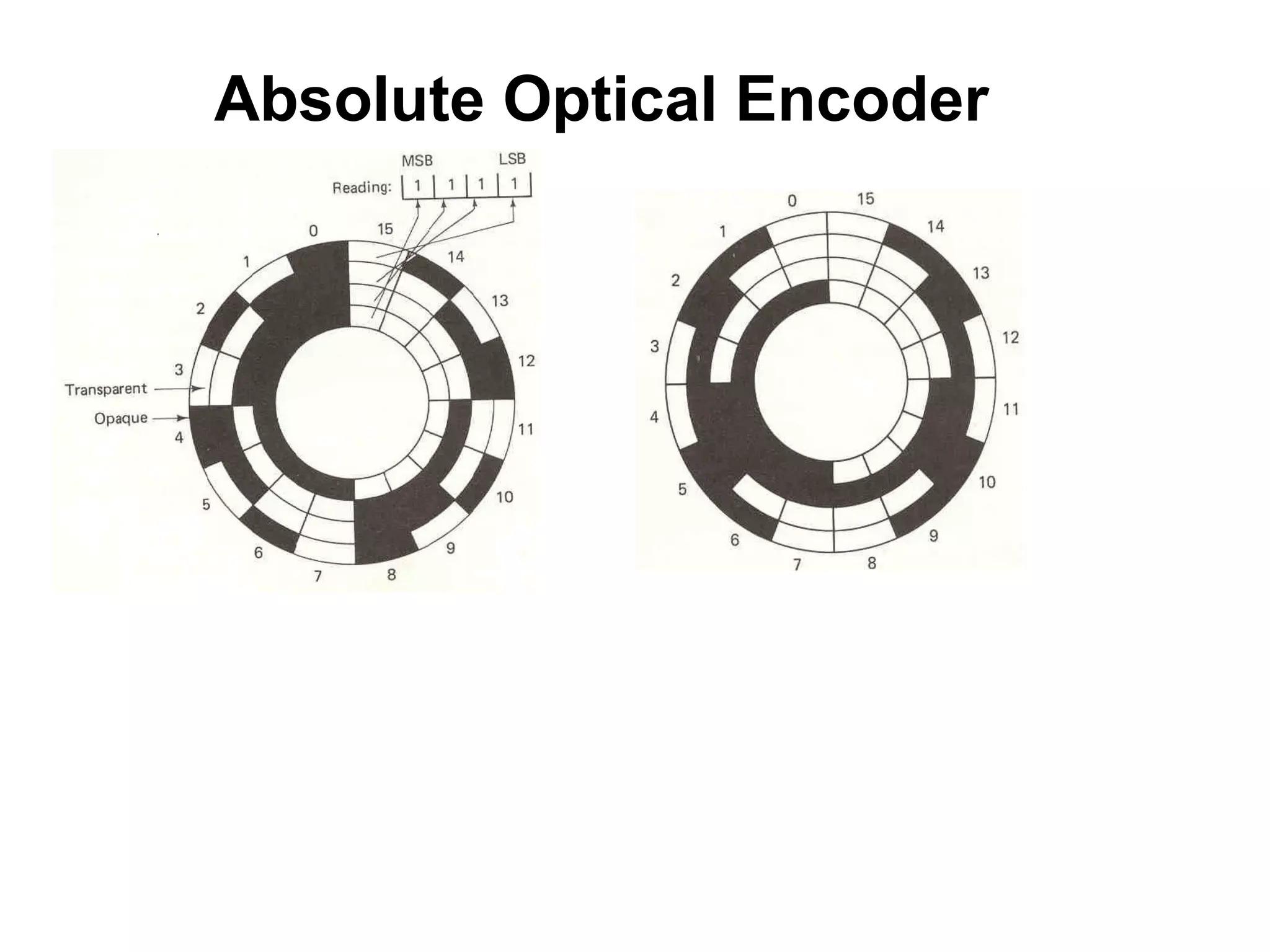
1.4 Optical Encoder
Whatis an encoder?
• An encoder is a device which converts a mechanical information of
a shaft or position into an electrical signal.
Encoder
33.
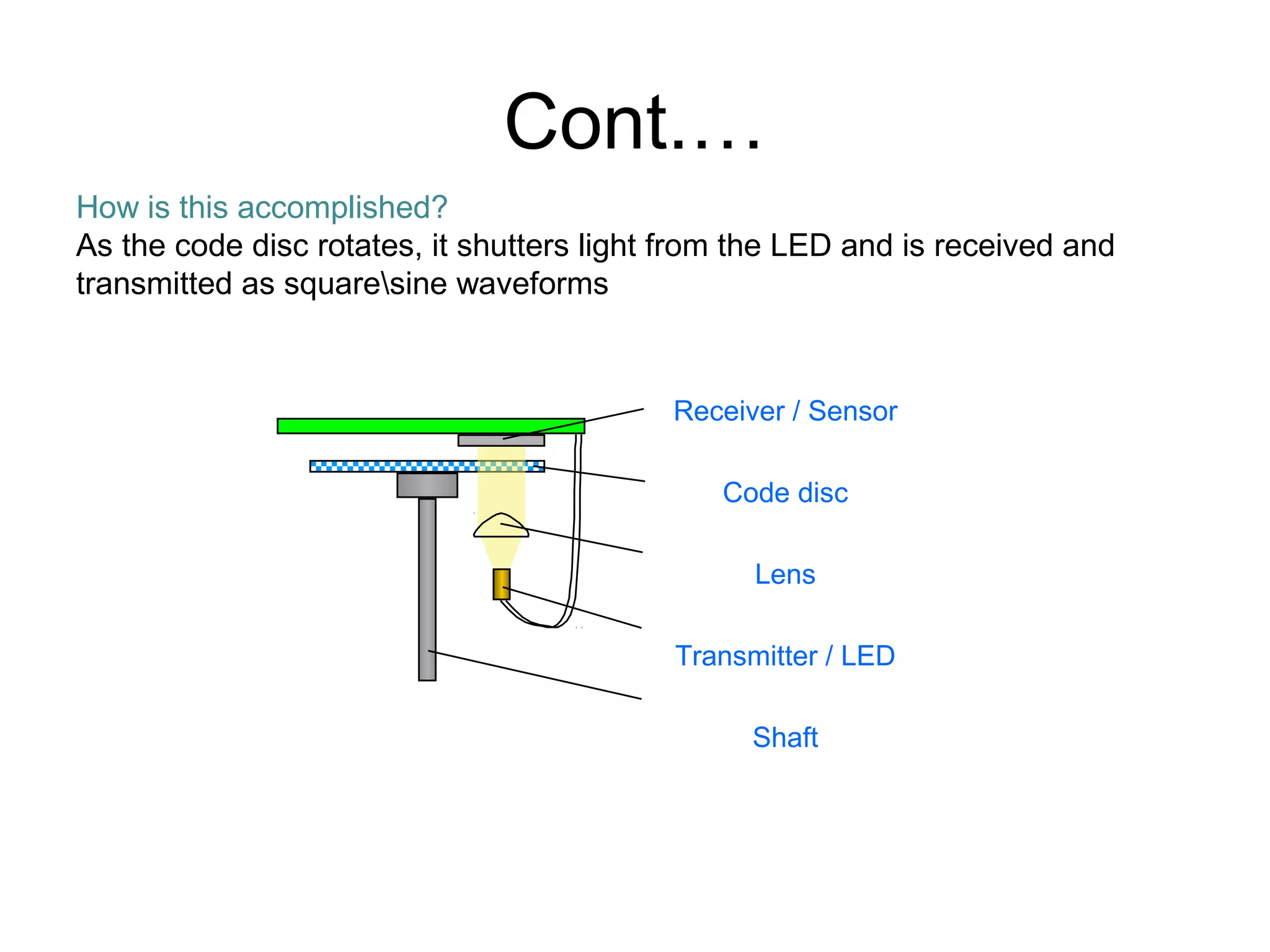
Cont.…
How is thisaccomplished?
As the code disc rotates, it shutters light from the LED and is received and
transmitted as squaresine waveforms
Receiver / Sensor
Code disc
Lens
Transmitter / LED
Shaft
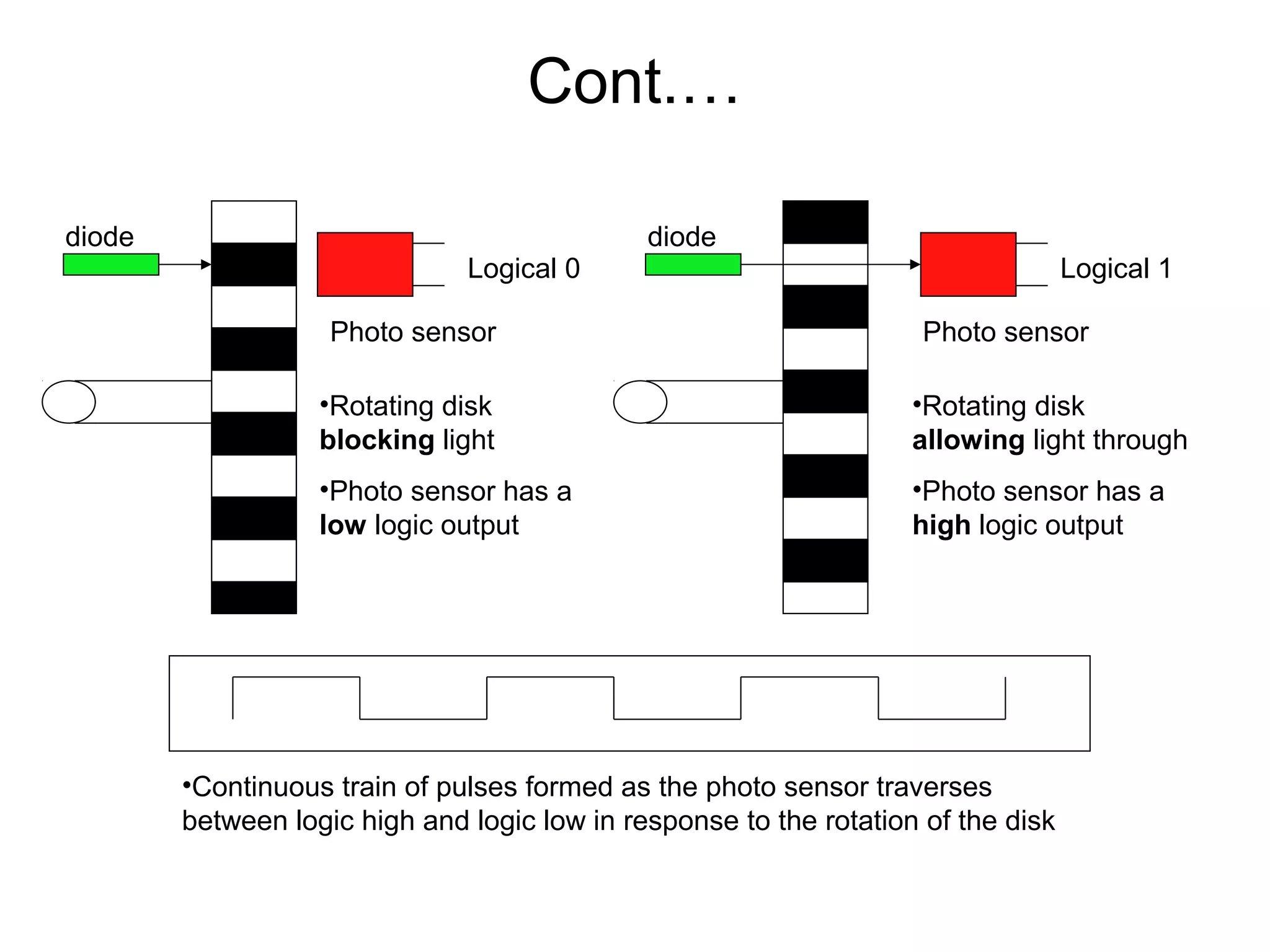
Cont.…
Photo sensor
diode
Photo sensor
diode
•Rotatingdisk
blocking light
•Photo sensor has a
low logic output
•Rotating disk
allowing light through
•Photo sensor has a
high logic output
•Continuous train of pulses formed as the photo sensor traverses
between logic high and logic low in response to the rotation of the disk
Logical 0 Logical 1
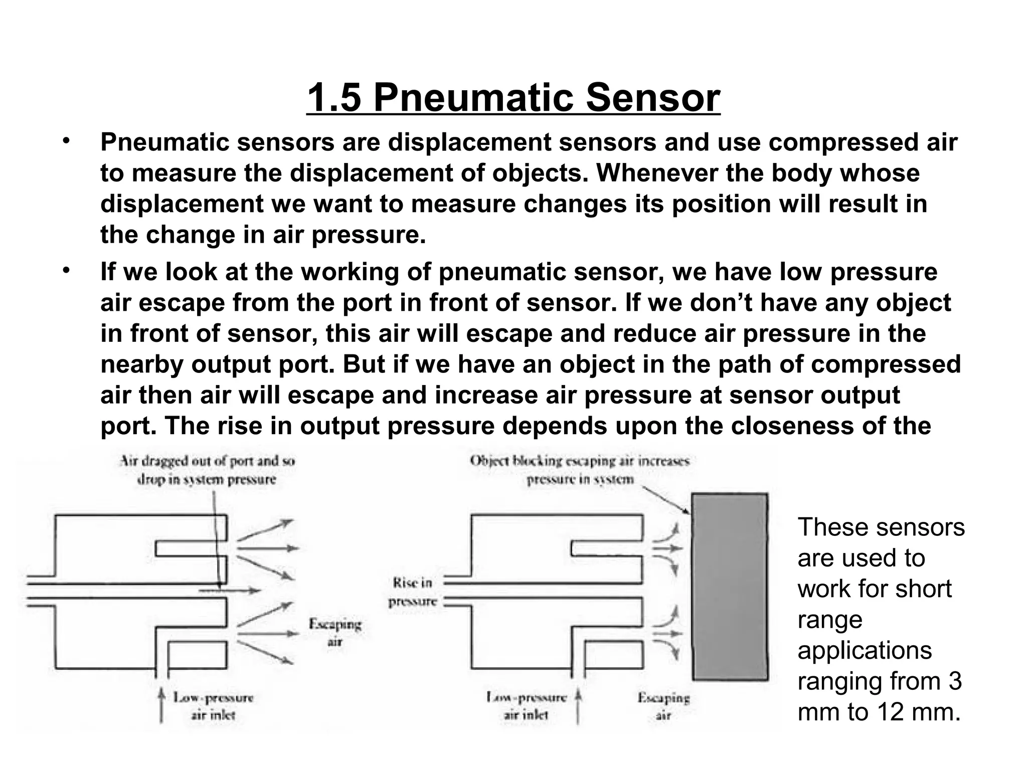
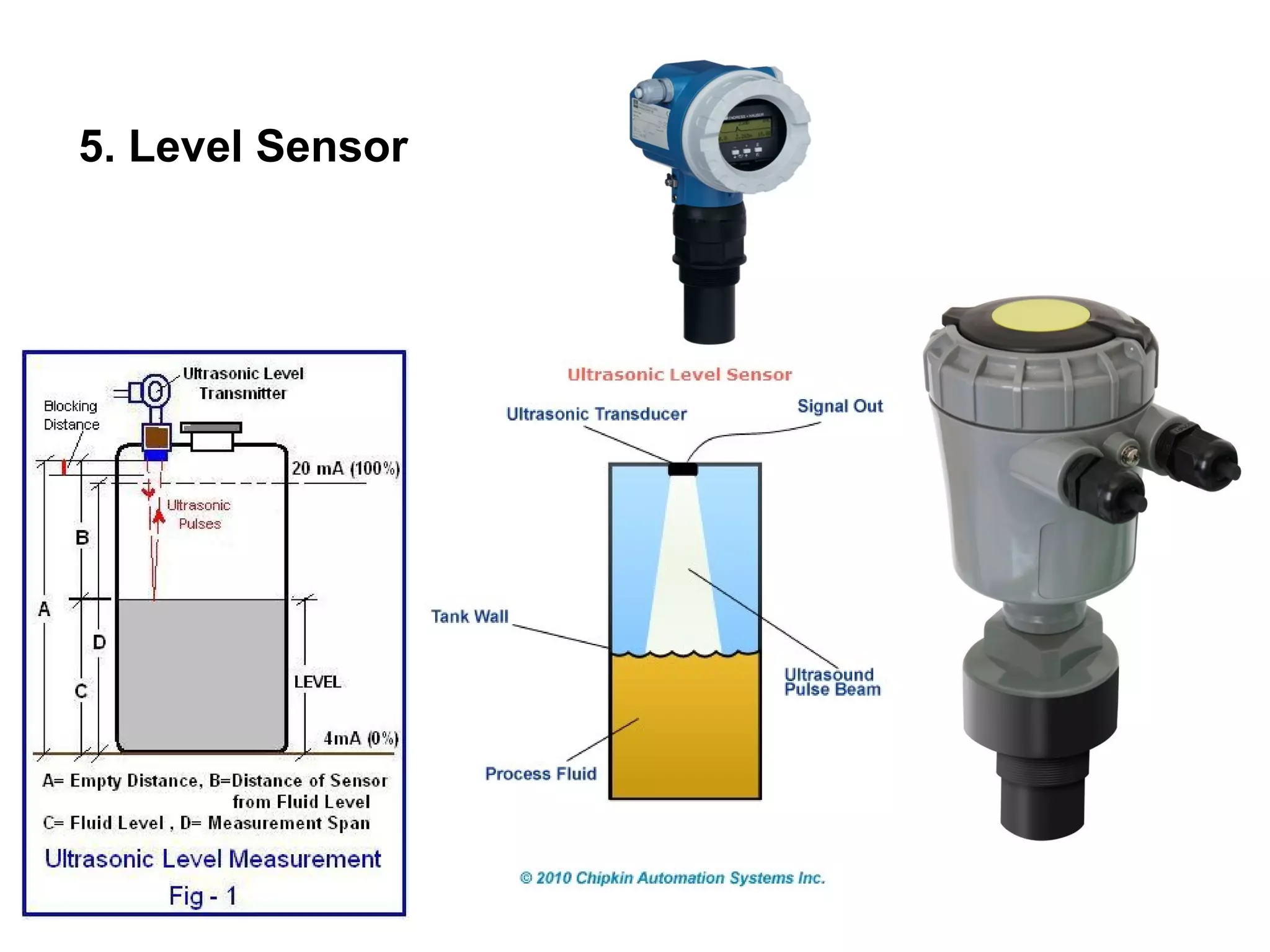
1.5 Pneumatic Sensor
•Pneumatic sensors are displacement sensors and use compressed air
to measure the displacement of objects. Whenever the body whose
displacement we want to measure changes its position will result in
the change in air pressure.
• If we look at the working of pneumatic sensor, we have low pressure
air escape from the port in front of sensor. If we don’t have any object
in front of sensor, this air will escape and reduce air pressure in the
nearby output port. But if we have an object in the path of compressed
air then air will escape and increase air pressure at sensor output
port. The rise in output pressure depends upon the closeness of the
object.
These sensors
are used to
work for short
range
applications
ranging from 3
mm to 12 mm.
40.
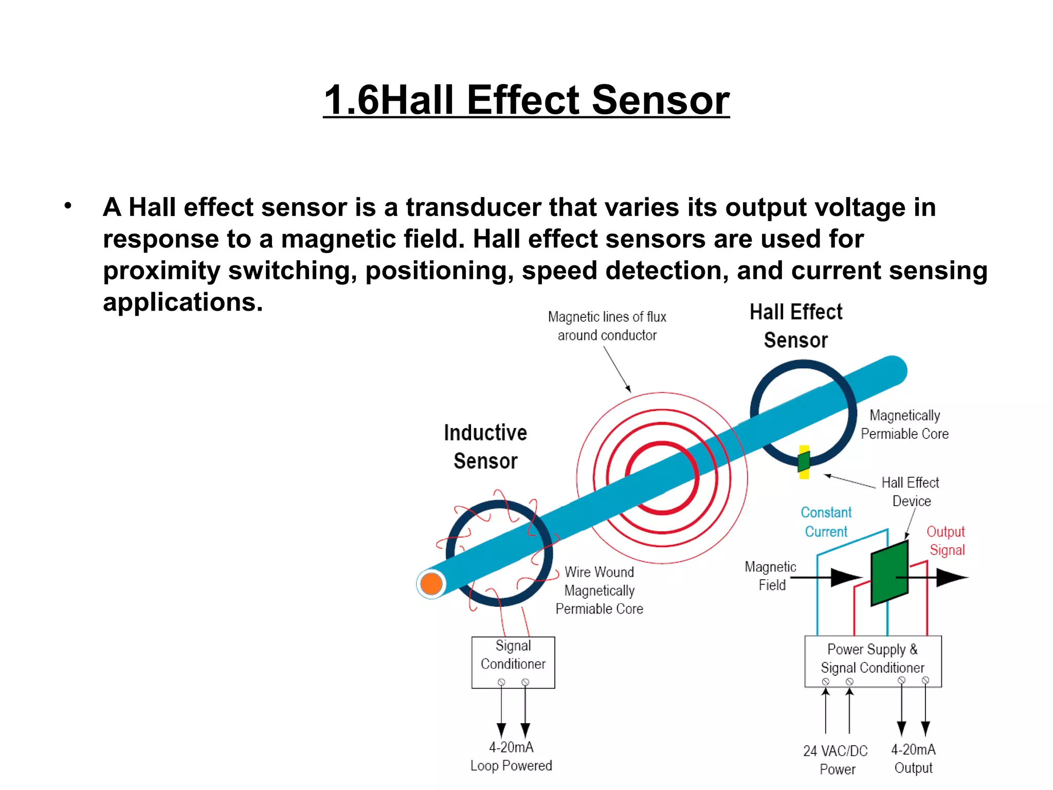
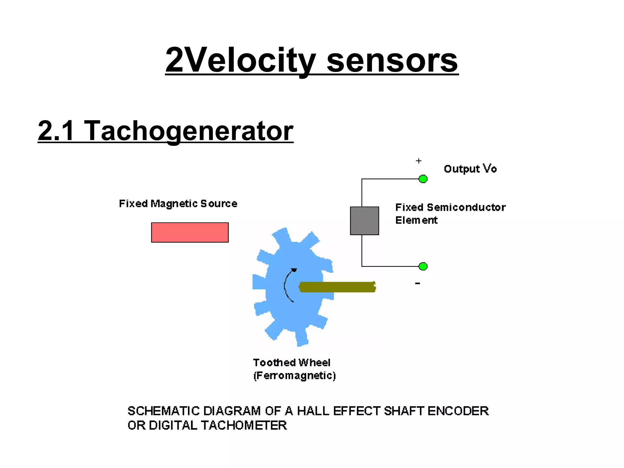
1.6Hall Effect Sensor
•A Hall effect sensor is a transducer that varies its output voltage in
response to a magnetic field. Hall effect sensors are used for
proximity switching, positioning, speed detection, and current sensing
applications.
The semiconductorelement and the magnetic source are fixed relative to one another in a single
package.
By moving the ferromagnetic member into the air gap between the magnetic source and the
semiconductor element, the flux linkage can be altered. This changes Vo.
Suitable both as an analog proximity sensor and as a limit switch.
The relationship between the output voltage Vo and the distance of a Hall effect sensor measured
from the moving member is non linear. Linear Hall effect sensors use calibration to linearize their
outputs.
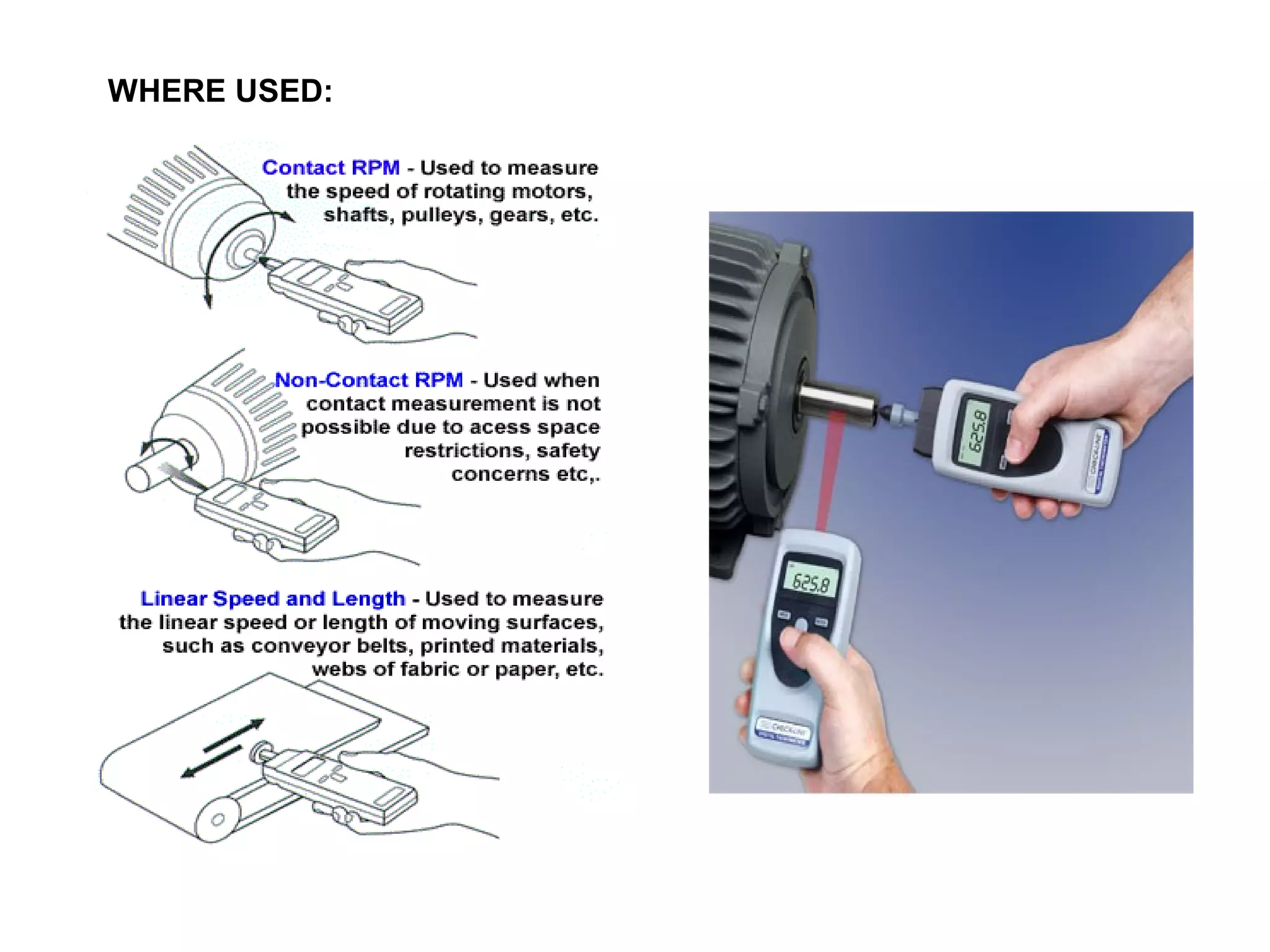
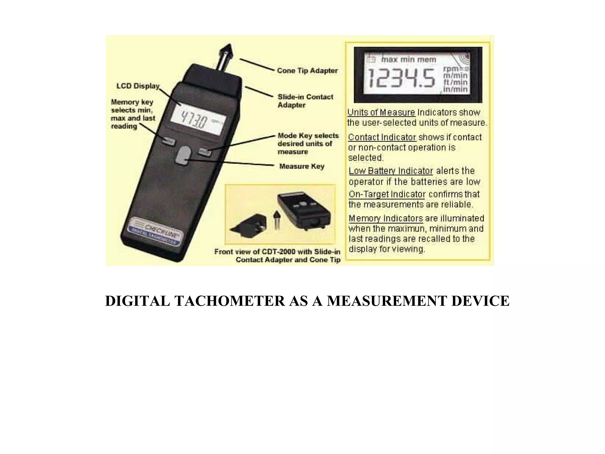
DIGITAL TACHOMETER
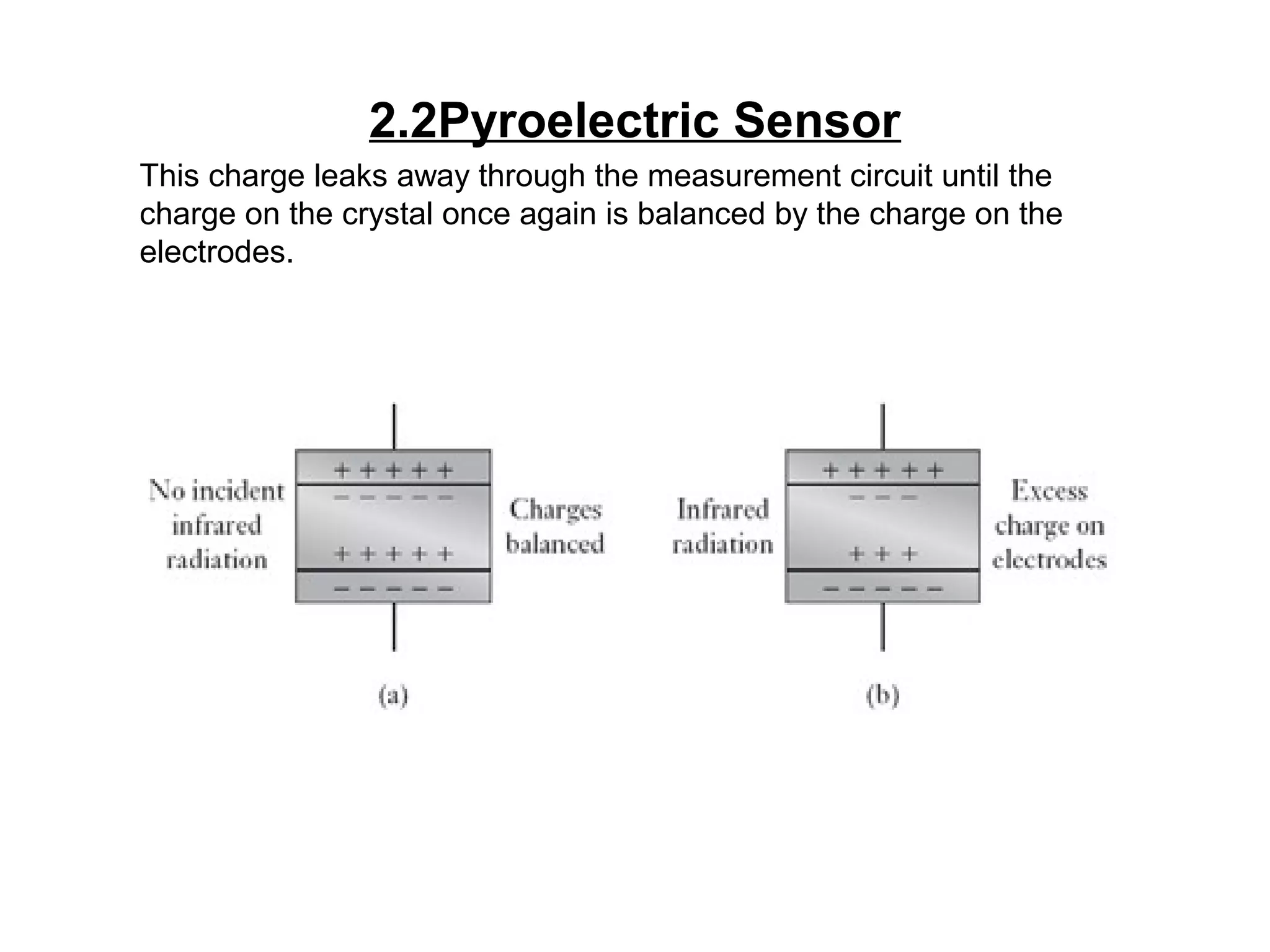
2.2Pyroelectric Sensor
This chargeleaks away through the measurement circuit until the
charge on the crystal once again is balanced by the charge on the
electrodes.
46.
Cont.…
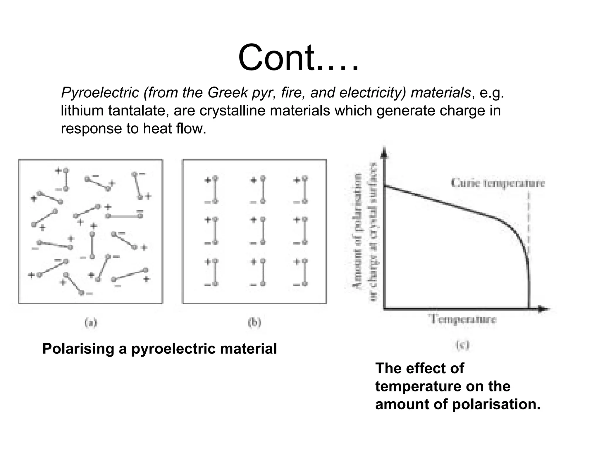
Pyroelectric (from theGreek pyr, fire, and electricity) materials, e.g.
lithium tantalate, are crystalline materials which generate charge in
response to heat flow.
Polarising a pyroelectric material
The effect of
temperature on the
amount of polarisation.
47.
Cont.…
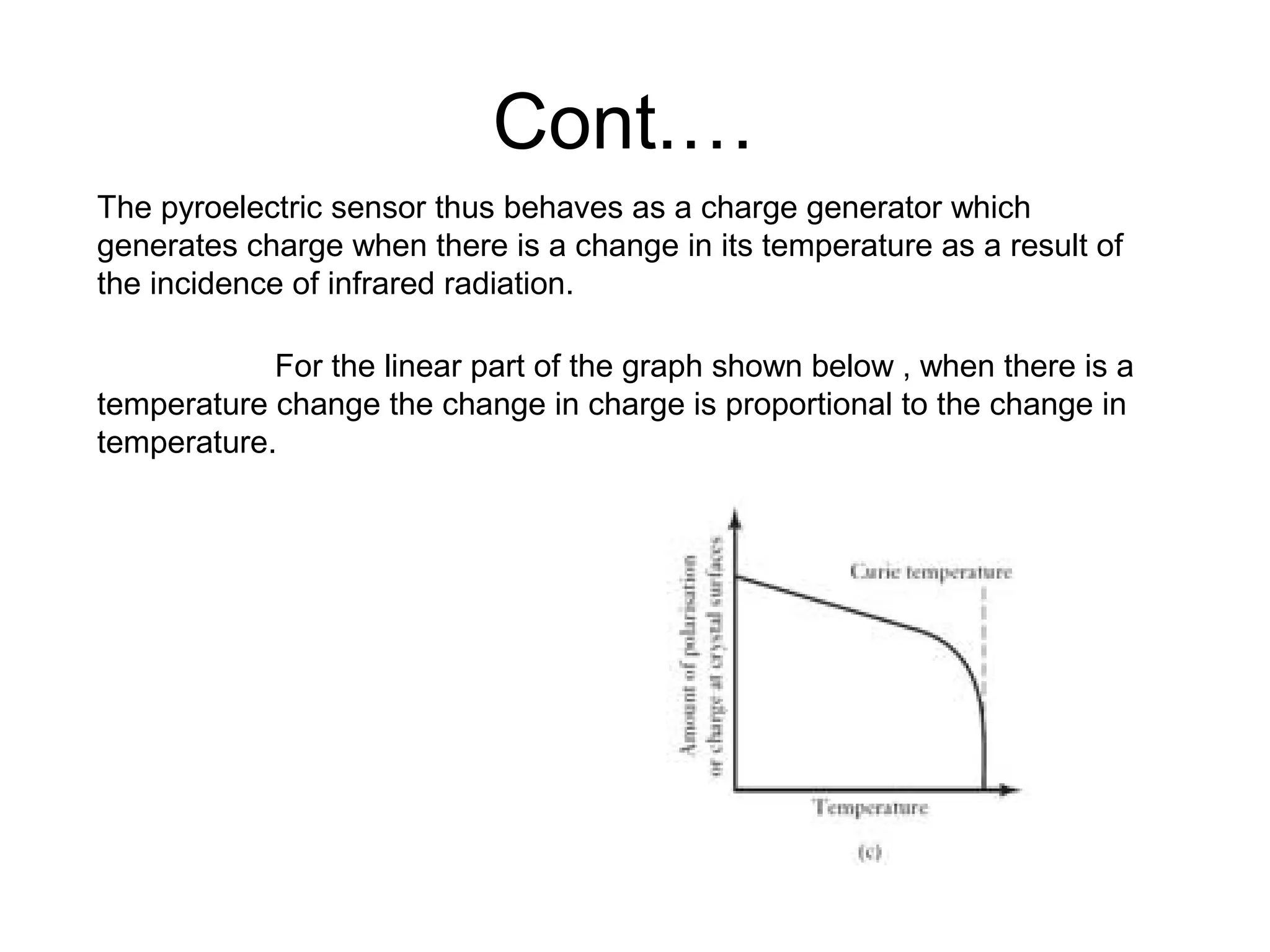
The pyroelectric sensorthus behaves as a charge generator which
generates charge when there is a change in its temperature as a result of
the incidence of infrared radiation.
For the linear part of the graph shown below , when there is a
temperature change the change in charge is proportional to the change in
temperature.
48.
Cont…
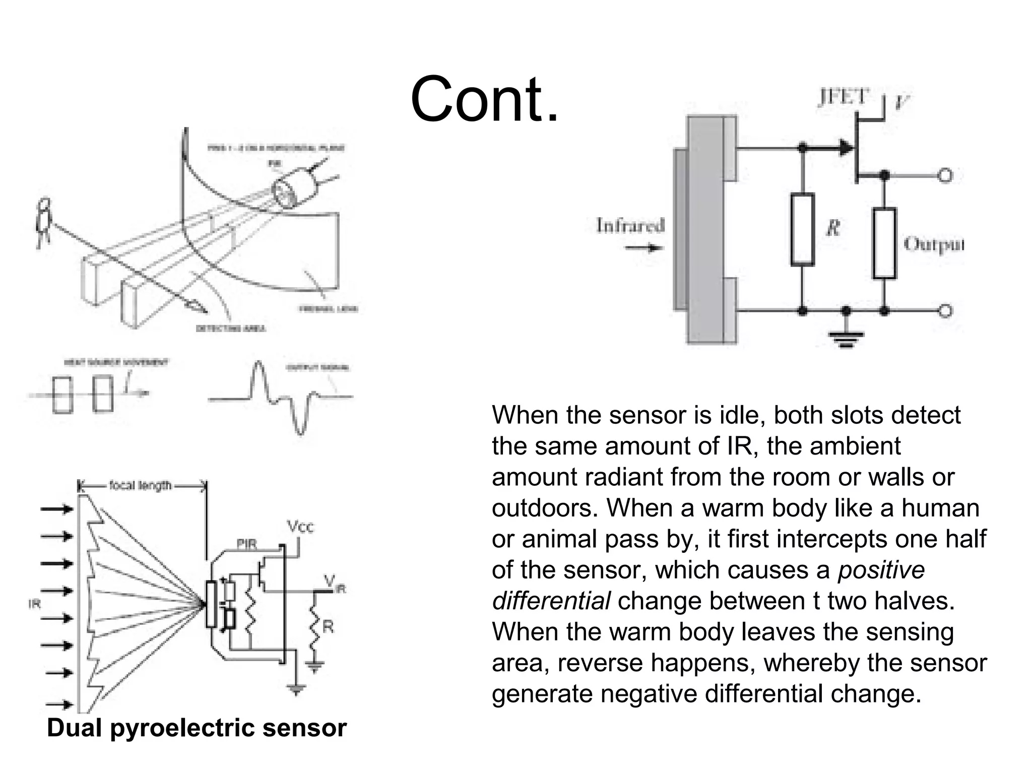
Dual pyroelectric sensor
Whenthe sensor is idle, both slots detect
the same amount of IR, the ambient
amount radiant from the room or walls or
outdoors. When a warm body like a human
or animal pass by, it first intercepts one half
of the sensor, which causes a positive
differential change between t two halves.
When the warm body leaves the sensing
area, reverse happens, whereby the sensor
generate negative differential change.
49.
3.FORCE SENSOR
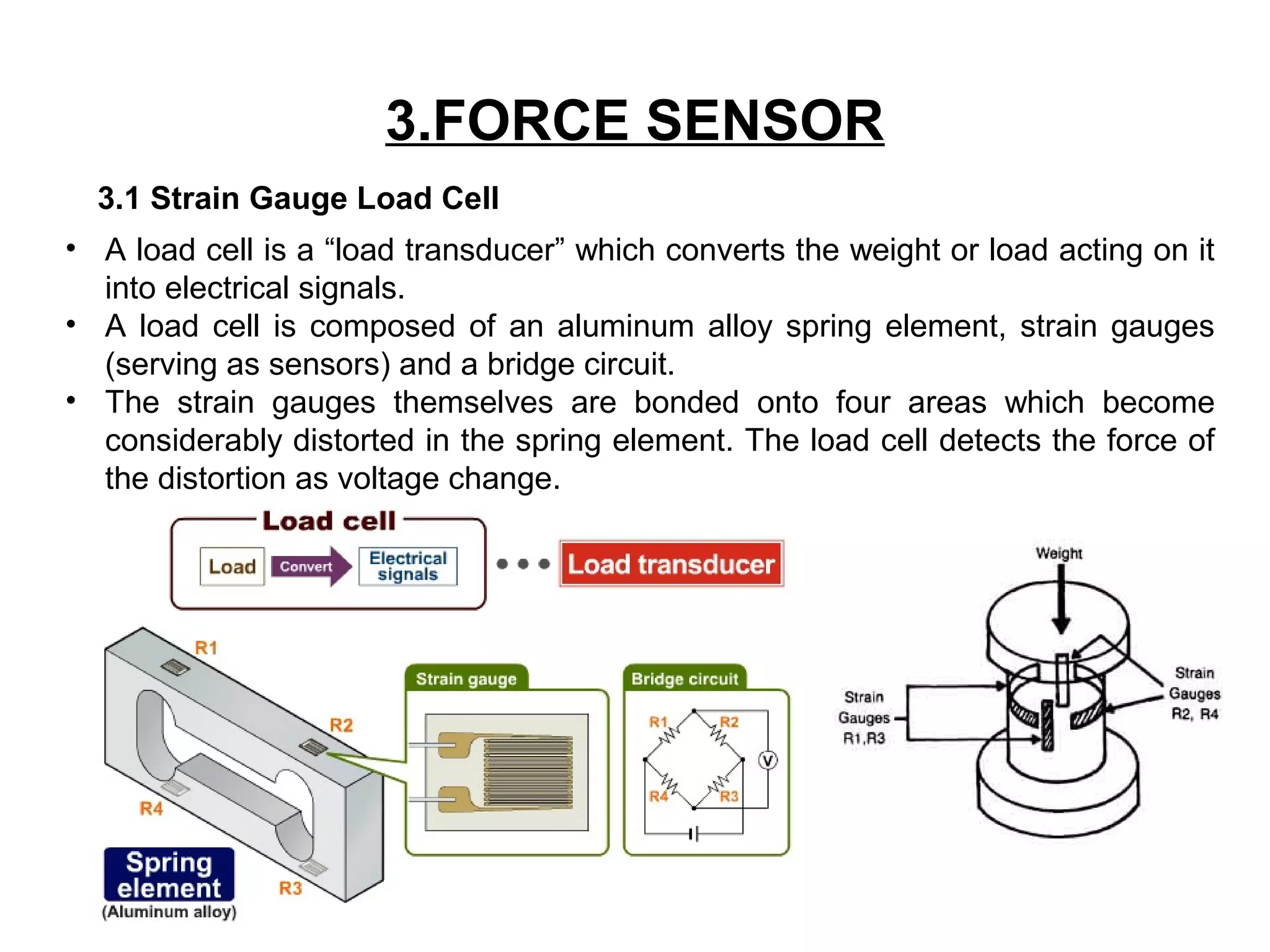
3.1 StrainGauge Load Cell
• A load cell is a “load transducer” which converts the weight or load acting on it
into electrical signals.
• A load cell is composed of an aluminum alloy spring element, strain gauges
(serving as sensors) and a bridge circuit.
• The strain gauges themselves are bonded onto four areas which become
considerably distorted in the spring element. The load cell detects the force of
the distortion as voltage change.
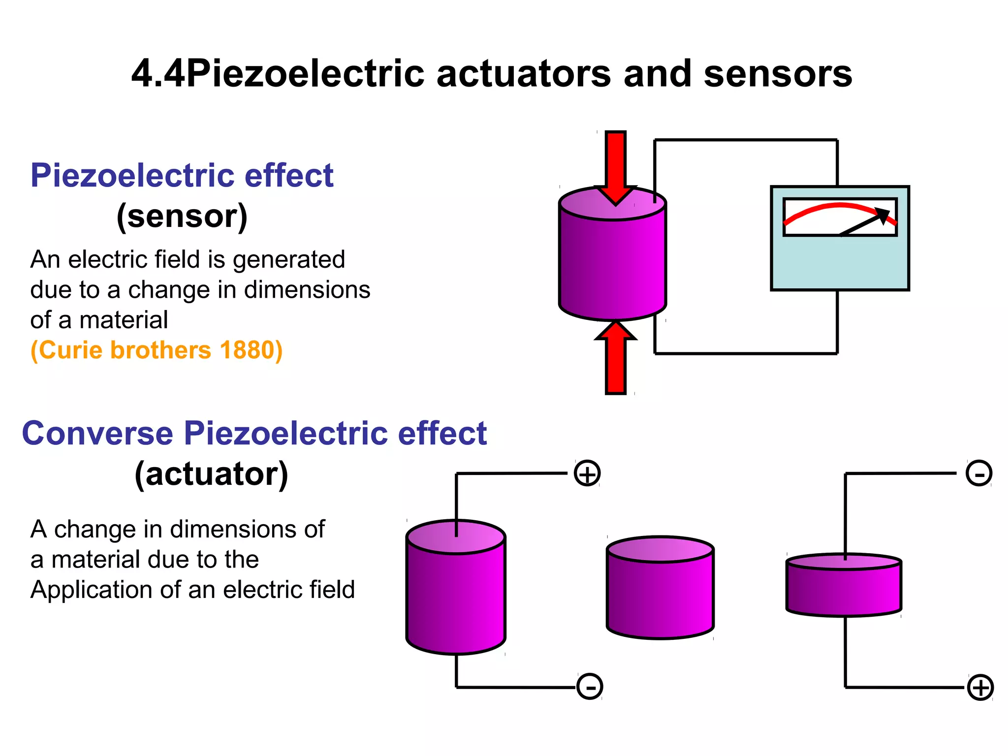
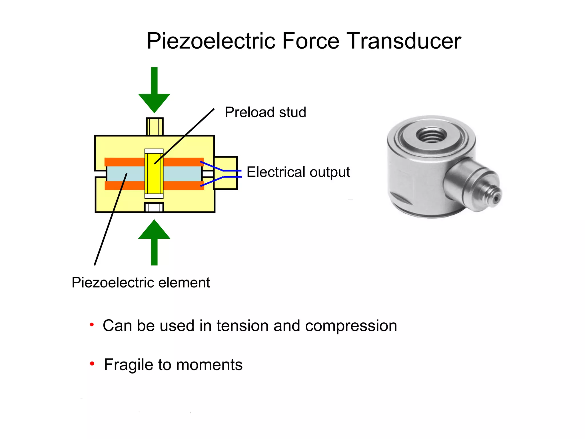
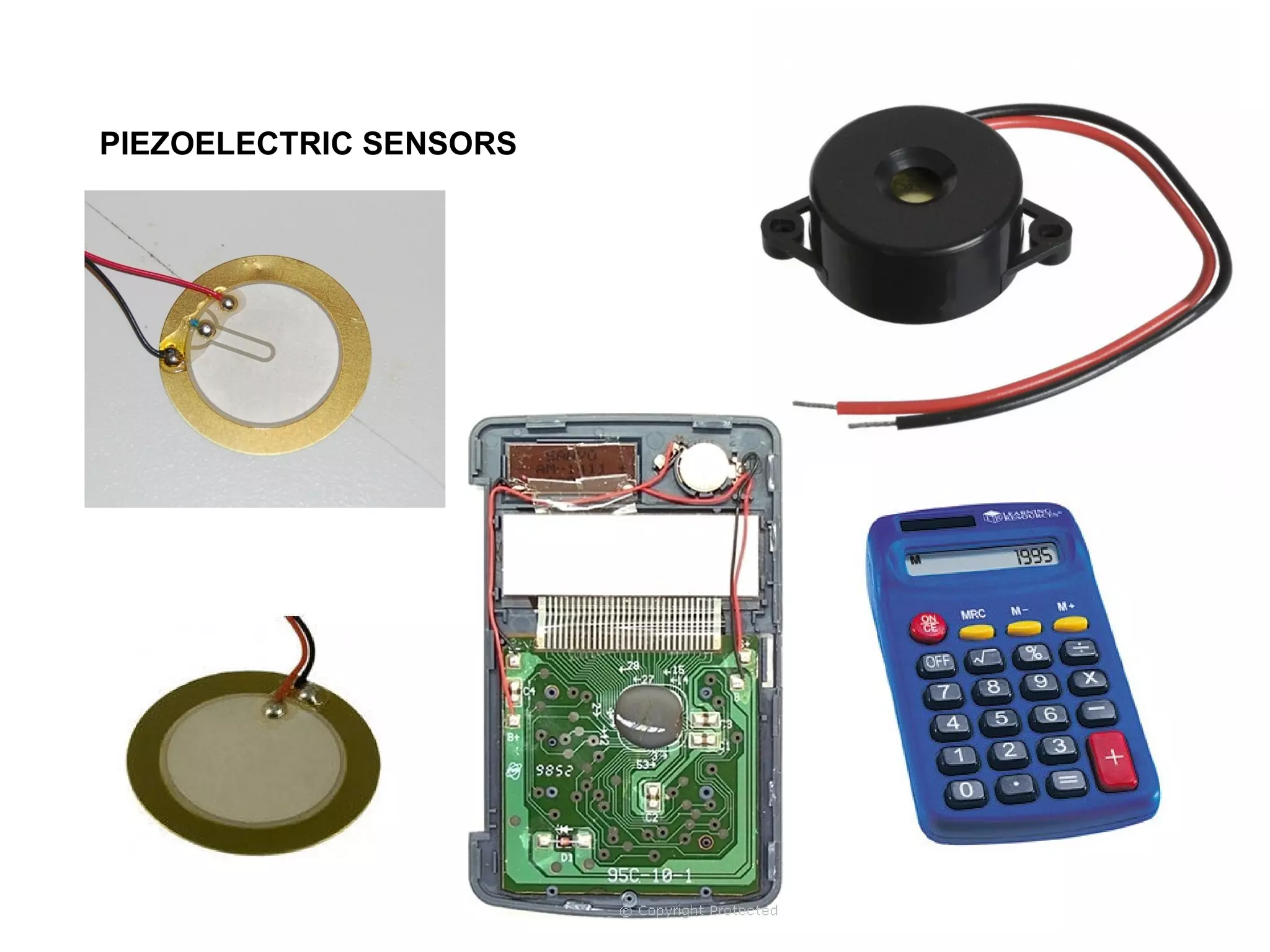
4.4Piezoelectric actuators andsensors
Piezoelectric effect
(sensor)
An electric field is generated
due to a change in dimensions
of a material
(Curie brothers 1880)
+
-
-
+
Converse Piezoelectric effect
(actuator)
A change in dimensions of
a material due to the
Application of an electric field
54.
Polarisation of apiezoelectric material
• Subject a piezoelectric material to a large voltage near the Curie temperature
then the dipoles align
• Curie temperature is the temperature above which the material loses its
piezoelectric property
dipole
55.
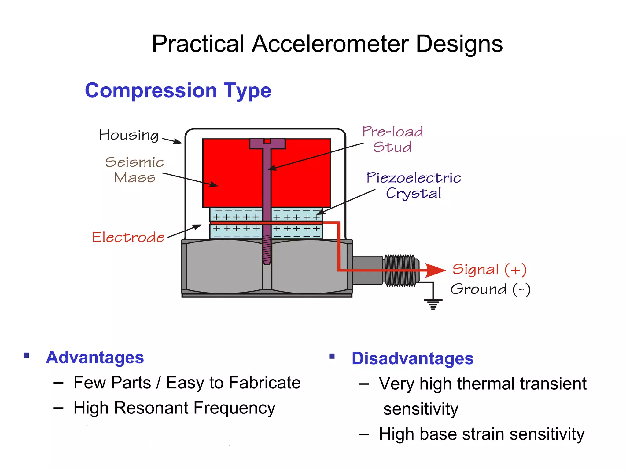
Practical Accelerometer Designs
Advantages
– Few Parts / Easy to Fabricate
– High Resonant Frequency
Compression Type
Disadvantages
– Very high thermal transient
sensitivity
– High base strain sensitivity
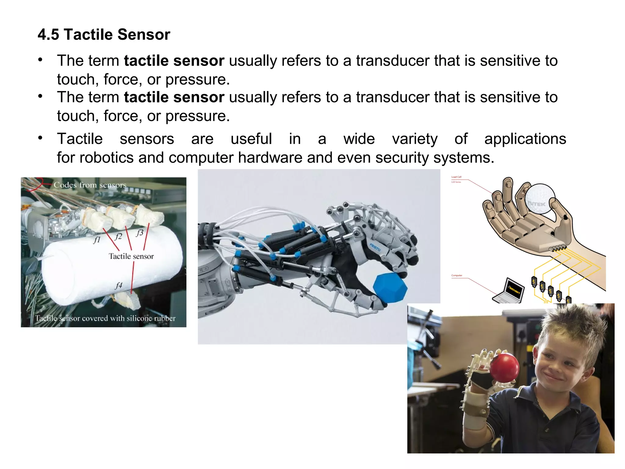
4.5 Tactile Sensor
•The term tactile sensor usually refers to a transducer that is sensitive to
touch, force, or pressure.
• The term tactile sensor usually refers to a transducer that is sensitive to
touch, force, or pressure.
• Tactile sensors are useful in a wide variety of applications
for robotics and computer hardware and even security systems.
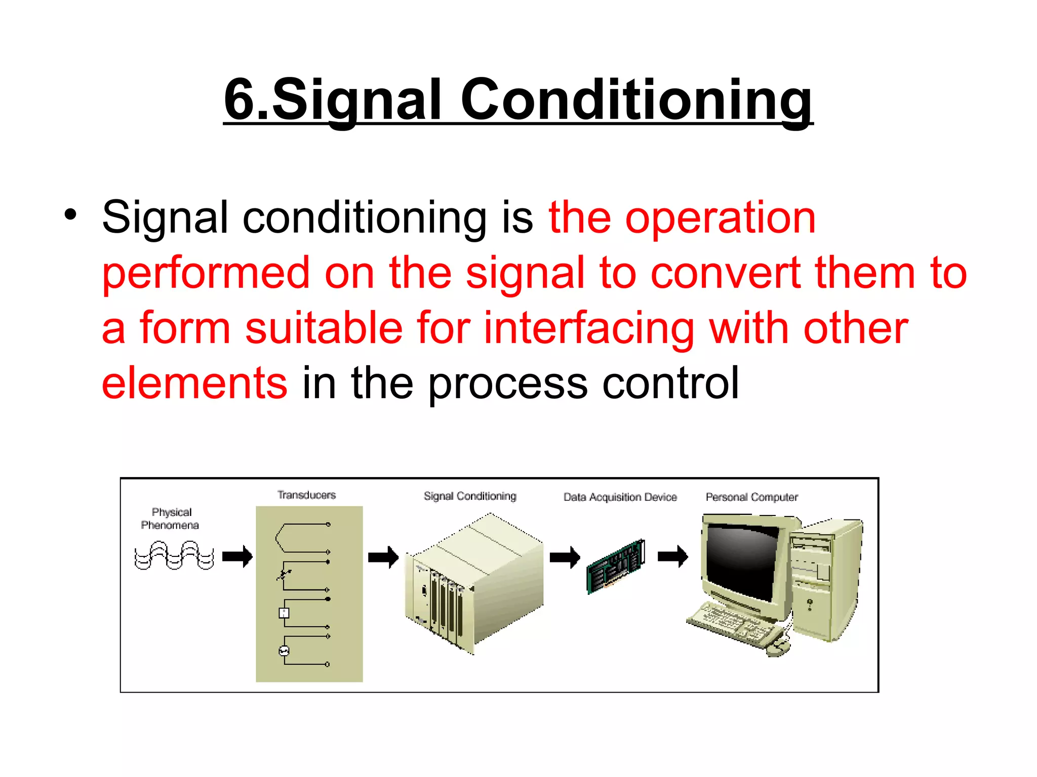
6.Signal Conditioning
• Signalconditioning is the operation
performed on the signal to convert them to
a form suitable for interfacing with other
elements in the process control
62.
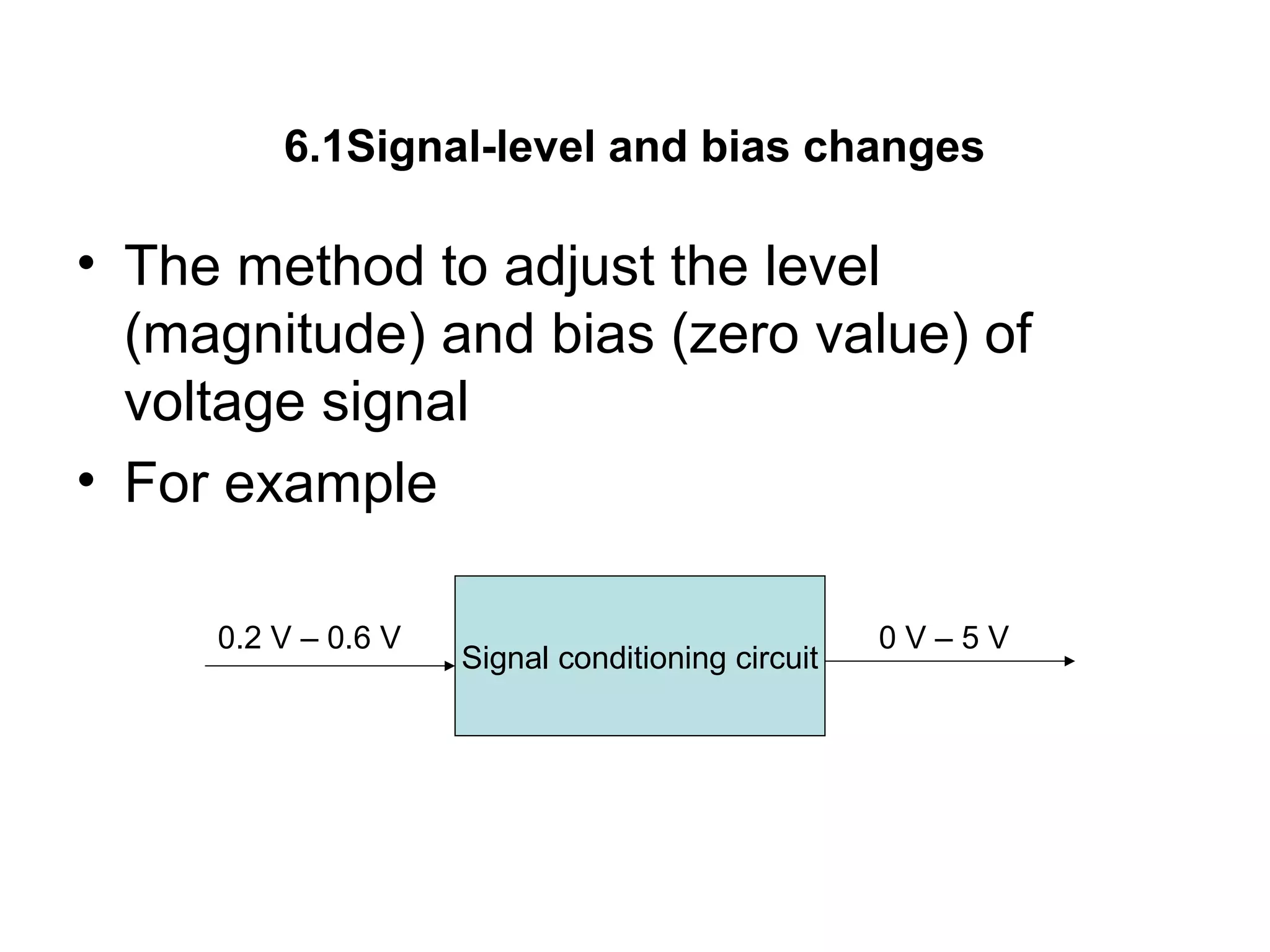
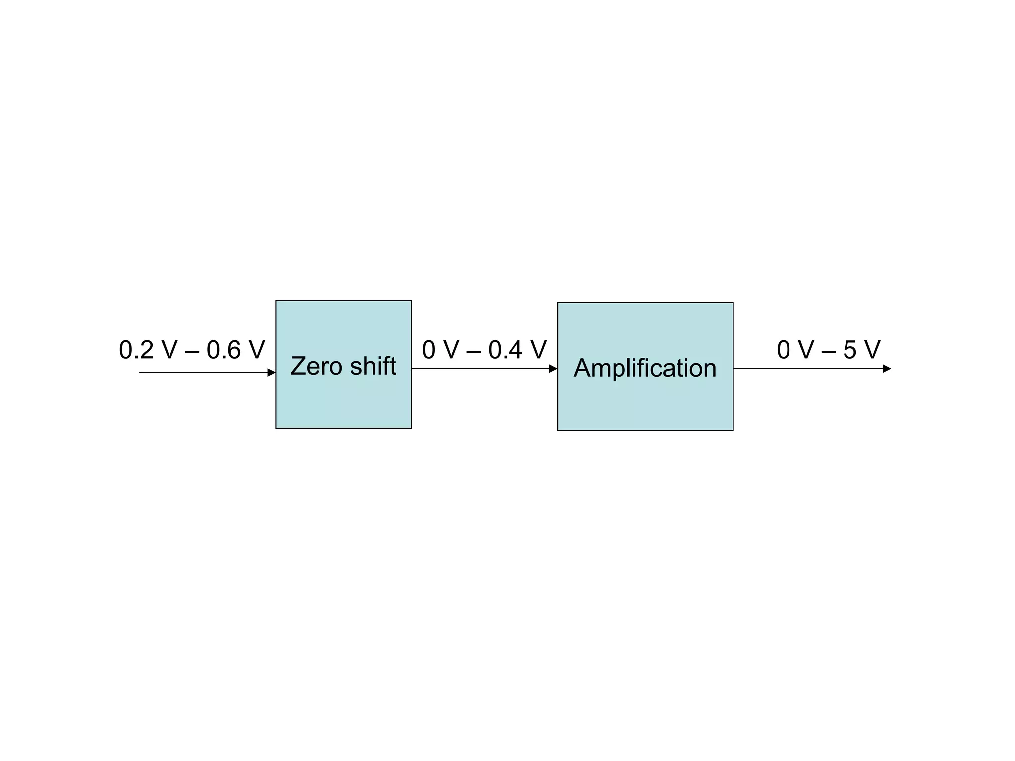
6.1Signal-level and biaschanges
• The method to adjust the level
(magnitude) and bias (zero value) of
voltage signal
• For example
Signal conditioning circuit
0.2 V – 0.6 V 0 V – 5 V
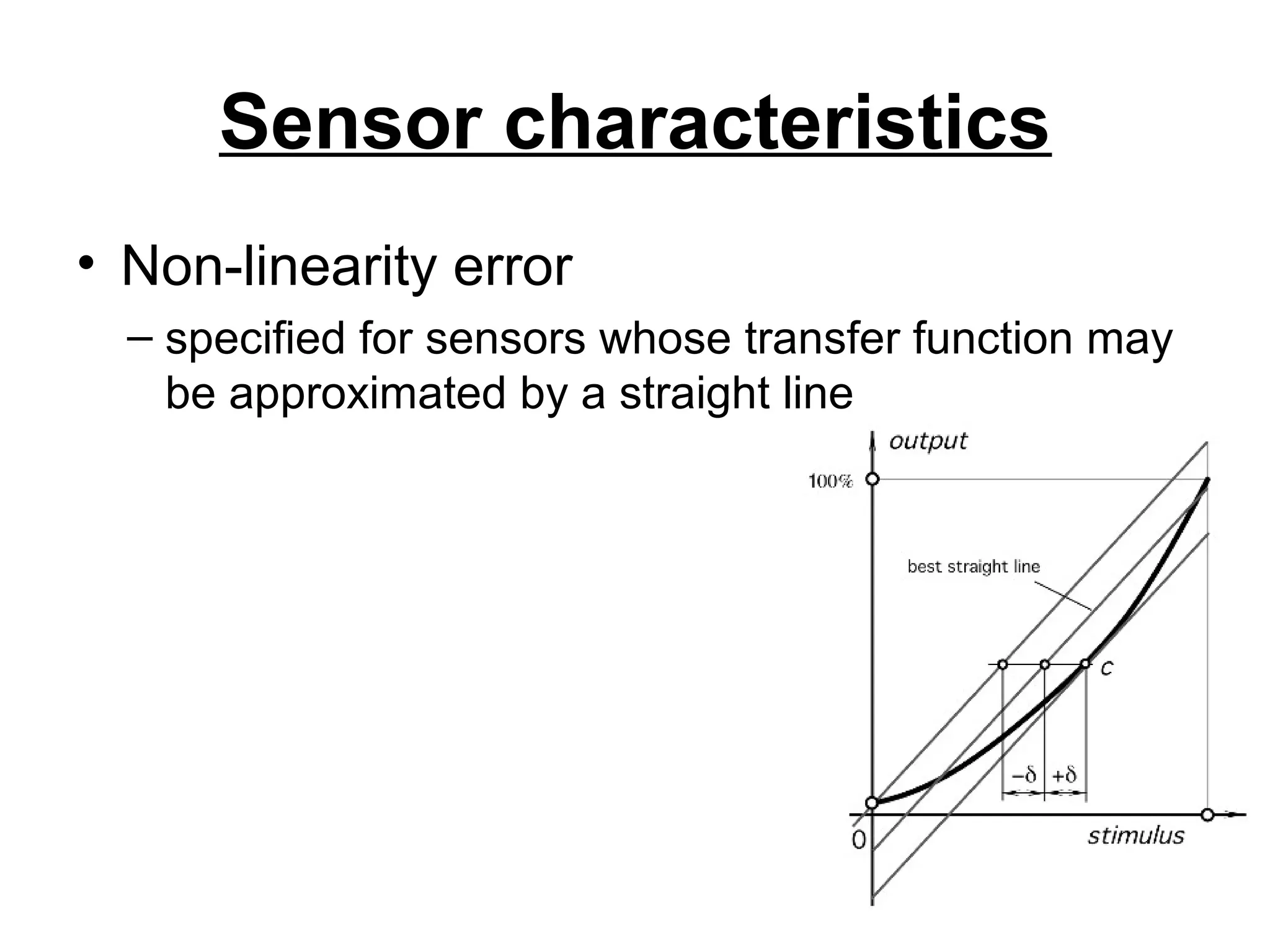
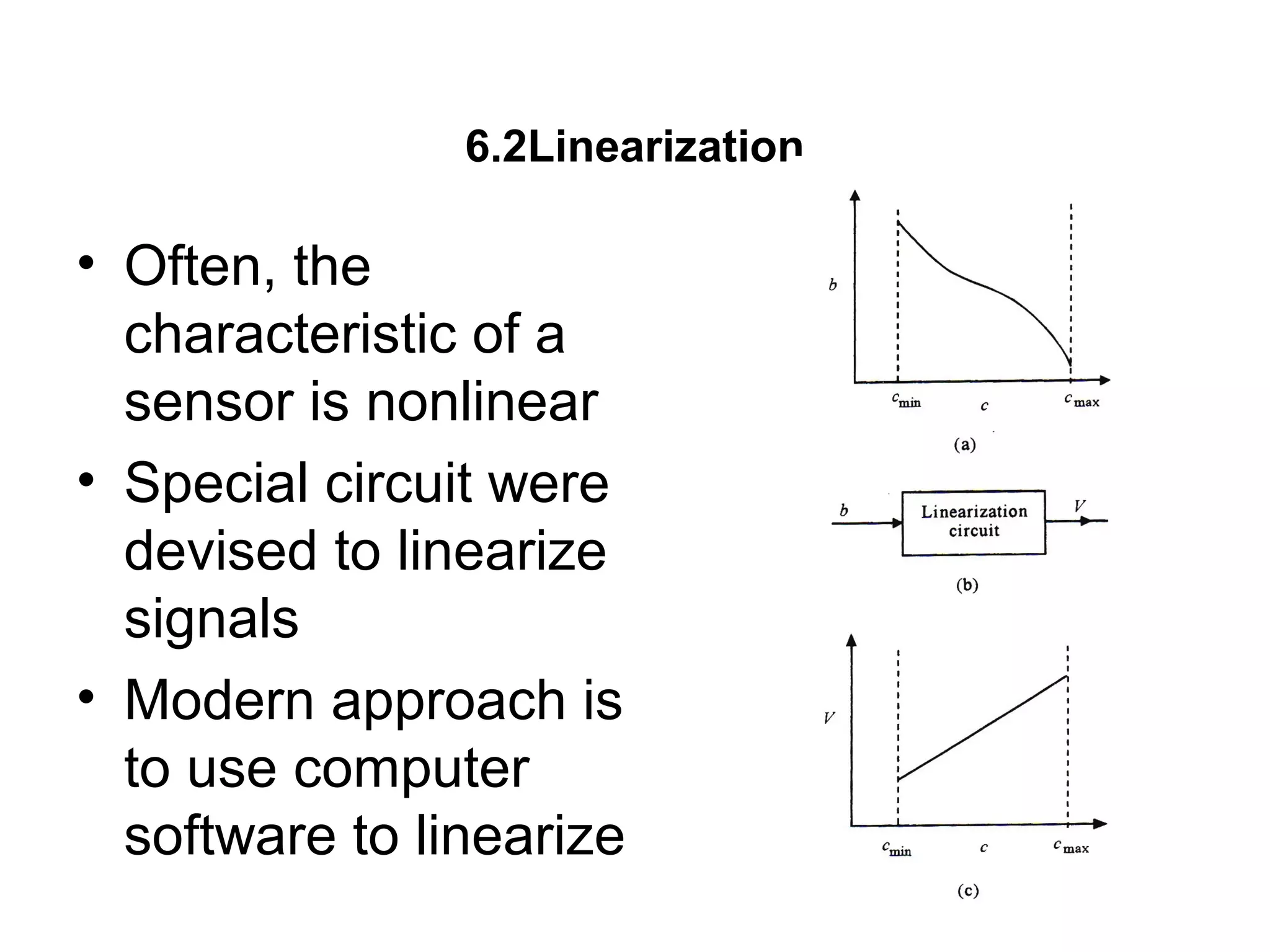
6.2Linearization
• Often, the
characteristicof a
sensor is nonlinear
• Special circuit were
devised to linearize
signals
• Modern approach is
to use computer
software to linearize
65.
6.3Conversion
• The circuitto covert one form of signal or
physical values into the other form
– Resistance to voltage
• Typical conversion is to convert resistance
or voltage to 4 to 20 mA and convert back
to voltage at the receiving end
• Thus, voltage-to-current and current-to-
voltage circuits are essential
66.
6.4Digital Interface
• Theuse of computer is process control
requires the conversion of analog to digital
signal
– ADC
– DAC
67.
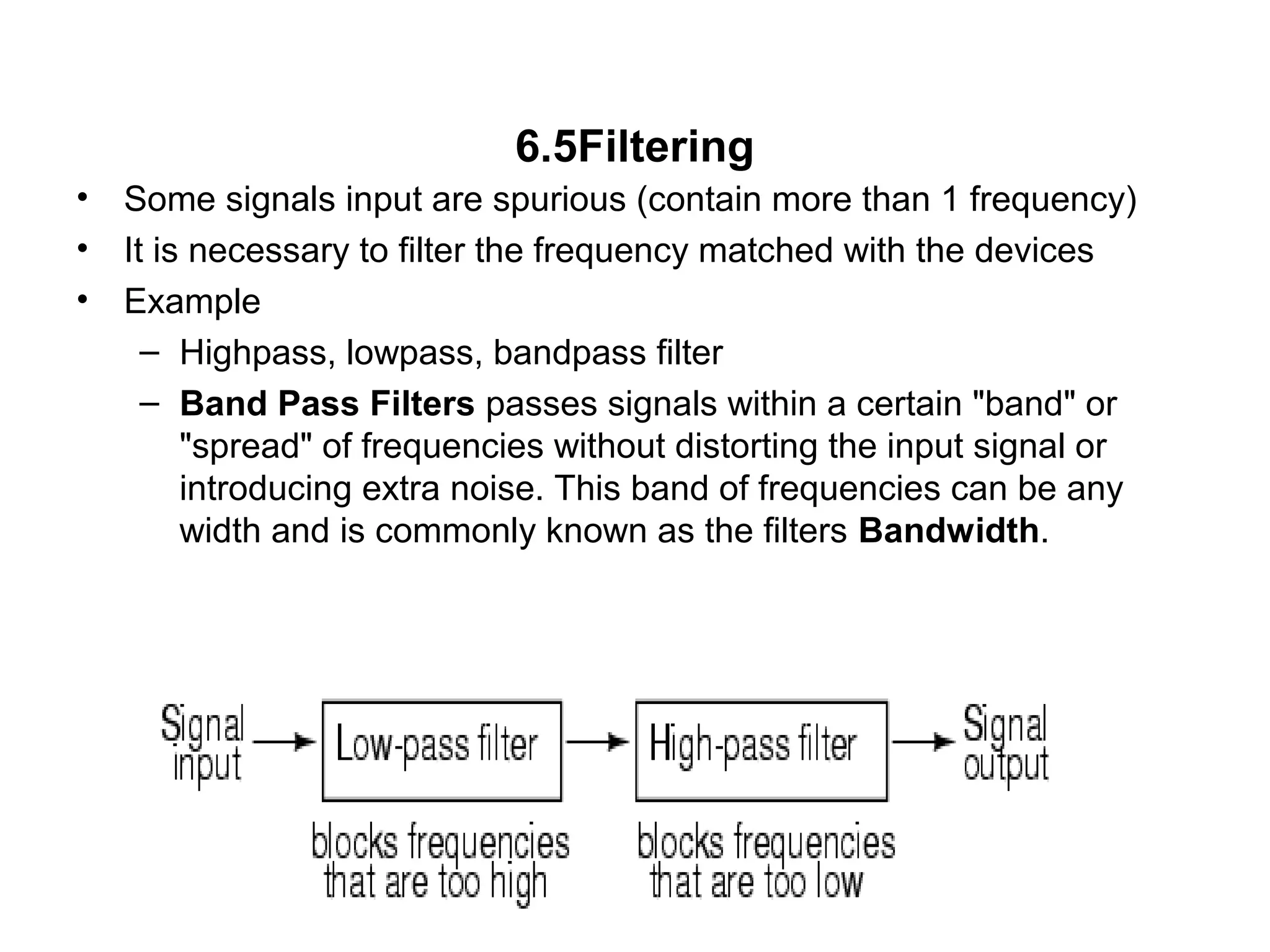
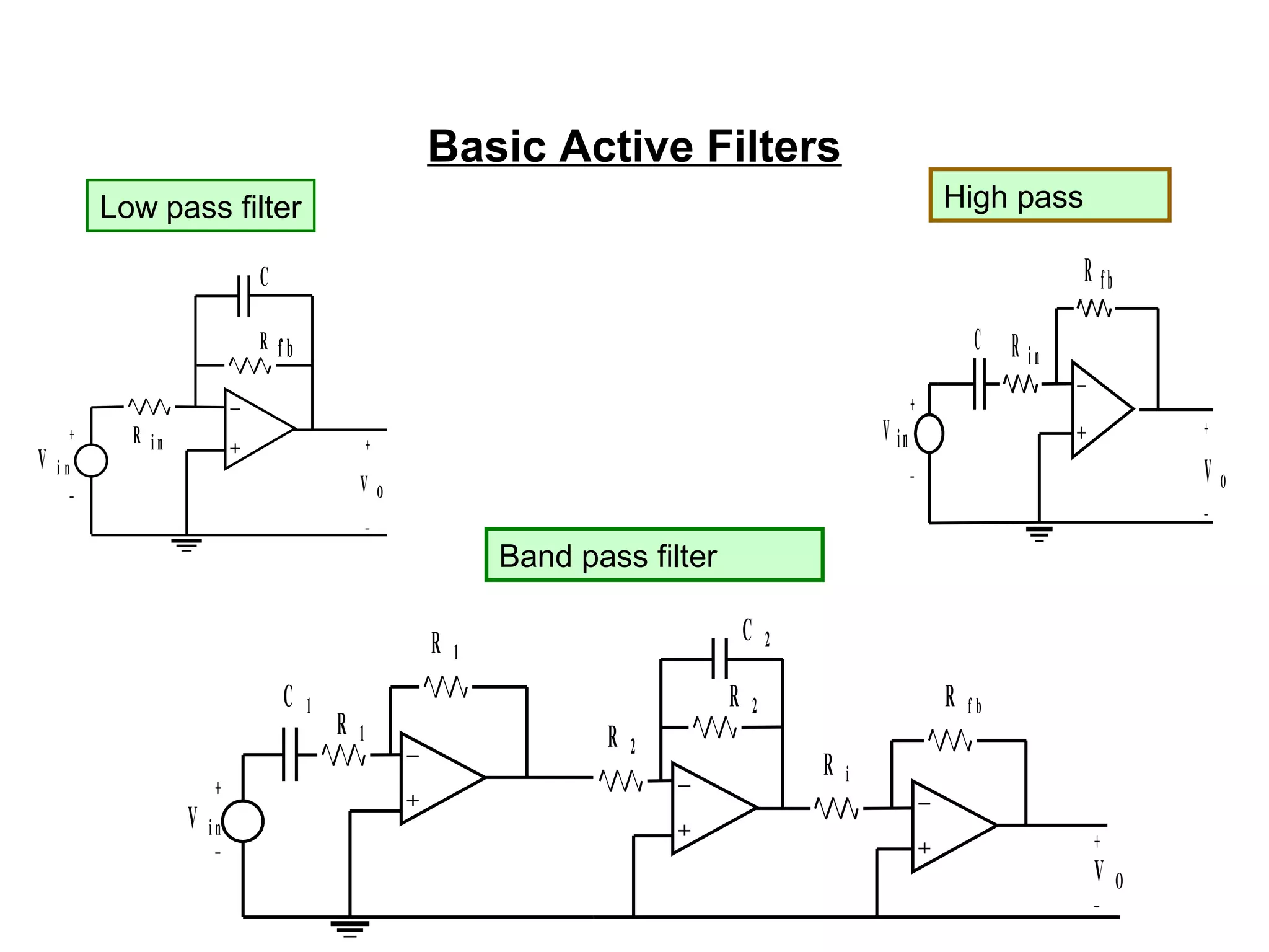
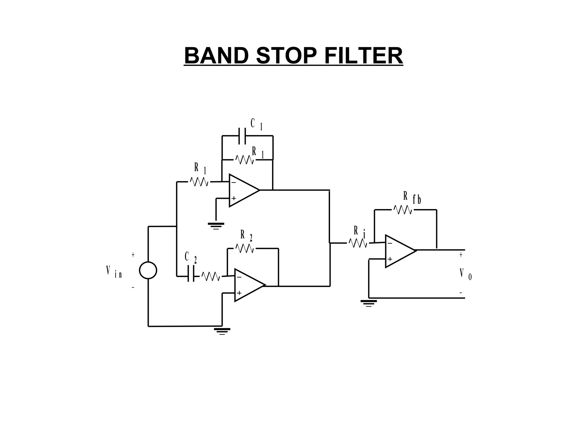
6.5Filtering
• Some signalsinput are spurious (contain more than 1 frequency)
• It is necessary to filter the frequency matched with the devices
• Example
– Highpass, lowpass, bandpass filter
– Band Pass Filters passes signals within a certain "band" or
"spread" of frequencies without distorting the input signal or
introducing extra noise. This band of frequencies can be any
width and is commonly known as the filters Bandwidth.
68.
• The passivefilter networks use only passive elements such as
resistors, inductors and capacitors.
• The active filter circuits use the active elements such as op-
amps, transistors along with the passive element.
• Modern active filters do not use inductors as they are bulky,
heavy & non-linear.
• The inductors generate the stray magnetic fields. They
dissipate considerable amount of power.
Cont.…
69.
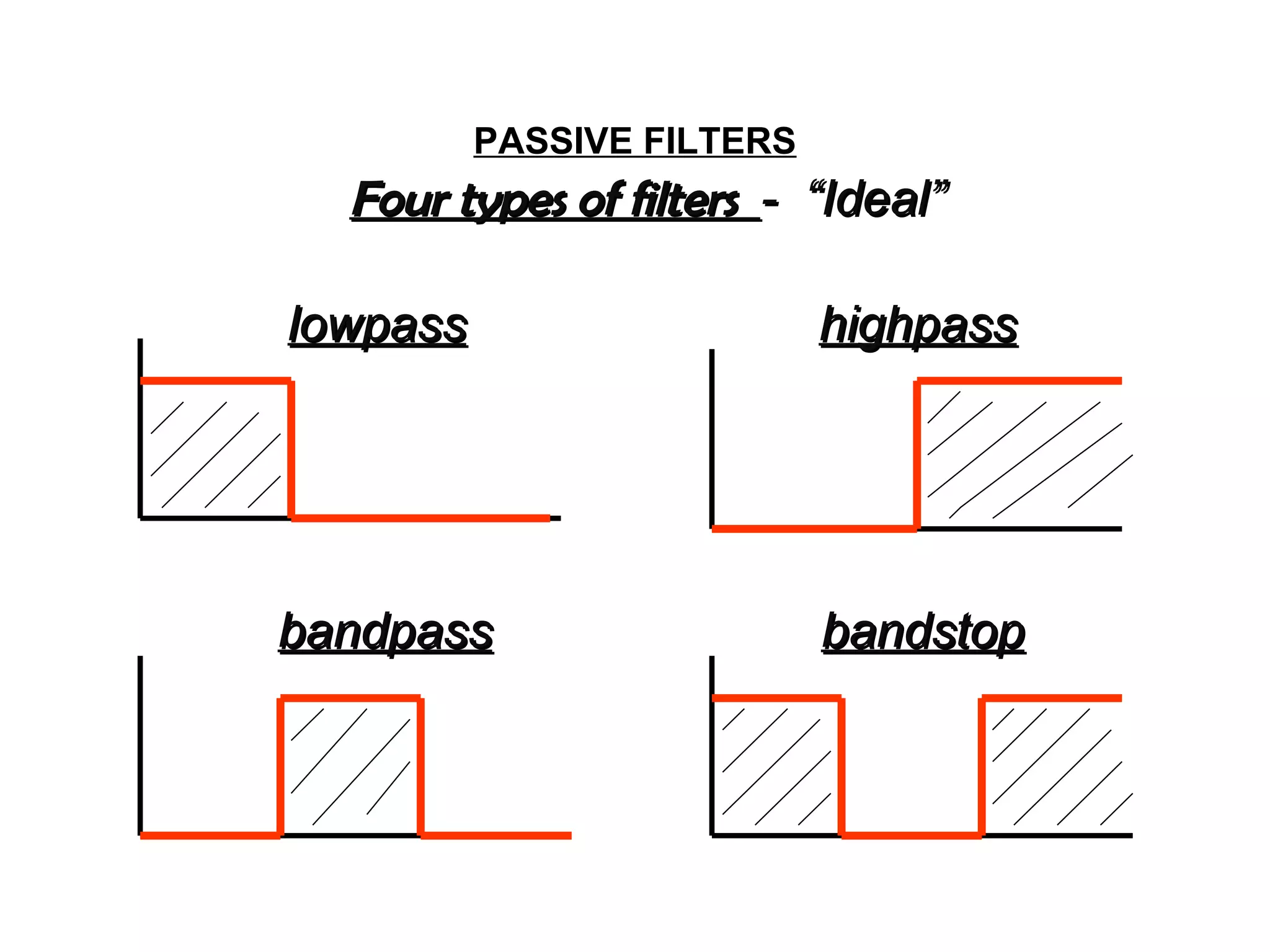
PASSIVE FILTERS
Four typesof filtersFour types of filters - “Ideal”- “Ideal”
lowpasslowpass highpasshighpass
bandpassbandpass bandstopbandstop
Basic Active Filters
Vi n
V O
C
R f b
+
_
+
_
R i n
Low pass filter
R i n
C
V in
R fb
V O
+
_
+
_
High pass
V i n
R 1
R 1
C 1
C 2
R 2
R 2
R f b
R i
V O
+
+
_
_
Band pass filter
6.6Impedance Matching
• Connectingthe sensors or process control
element with different impedance causes
signal reflection
• The network or circuit to match impedance
thus to reduce signal reflection
74.
6.7Concept of Loading
•When the sensor or circuit is connected to
load, this will introduce the uncertainty in
the measurement (amplitude of voltage)
75.
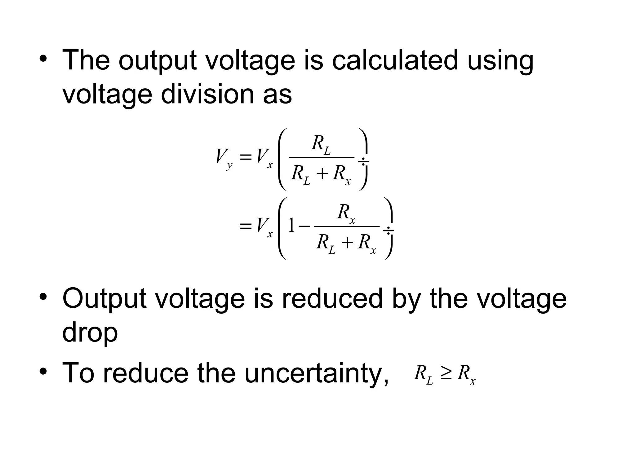
• The outputvoltage is calculated using
voltage division as
• Output voltage is reduced by the voltage
drop
• To reduce the uncertainty,
1
L
y x
L x
x
x
L x
R
V V
R R
R
V
R R
= ÷
+
= − ÷
+
L xR R≥
76.
7.Data acquisition
• Dataacquisition (DAQ) is the process of measuring an
electrical or physical phenomenon such as voltage,
current, temperature, pressure, or sound with a
computer.
• Data acquisition is the process of sampling signals
that measure real world physical conditions and
converting the resulting samples into digital numeric
values that can be manipulated by a computer
77.
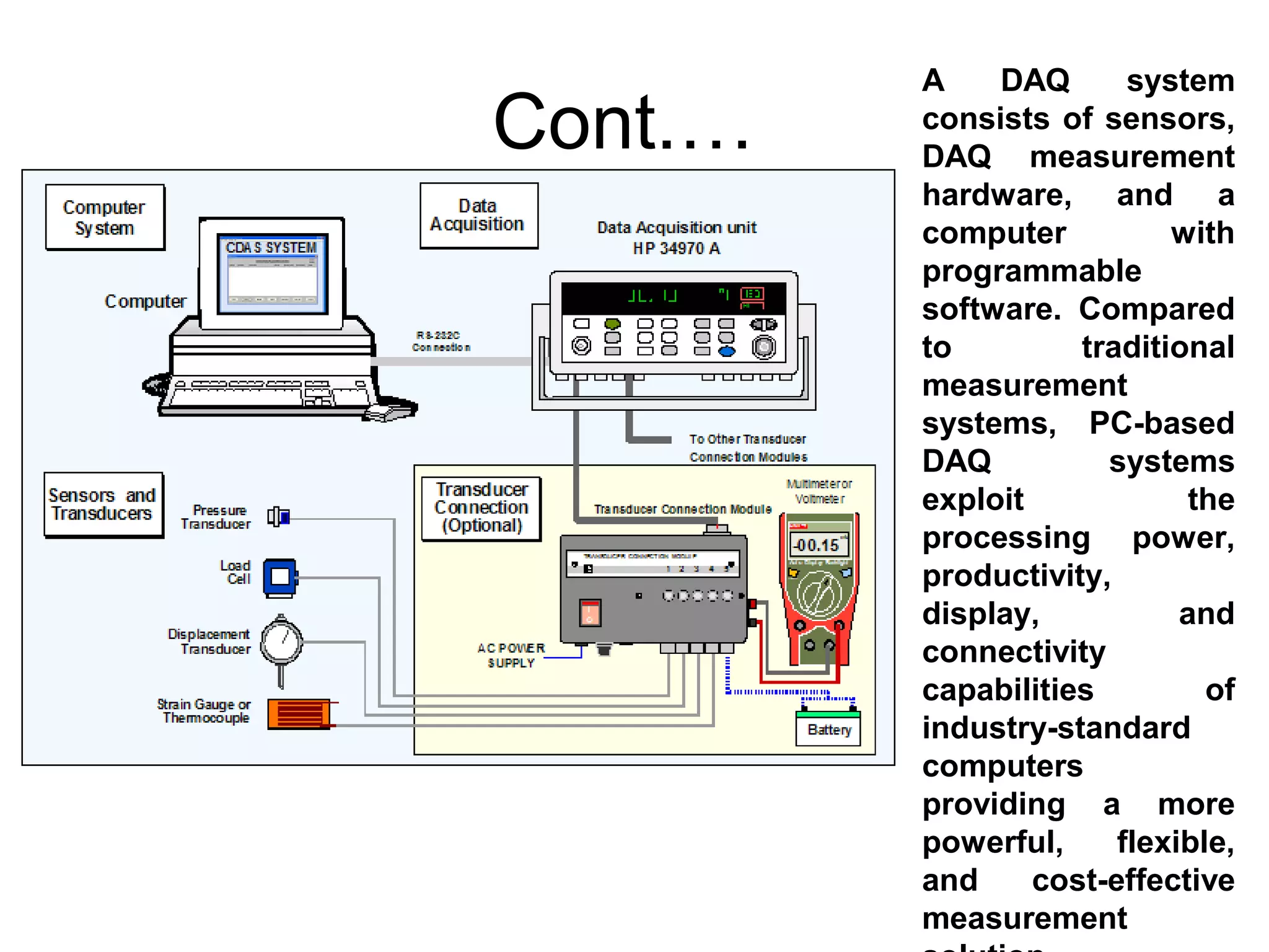
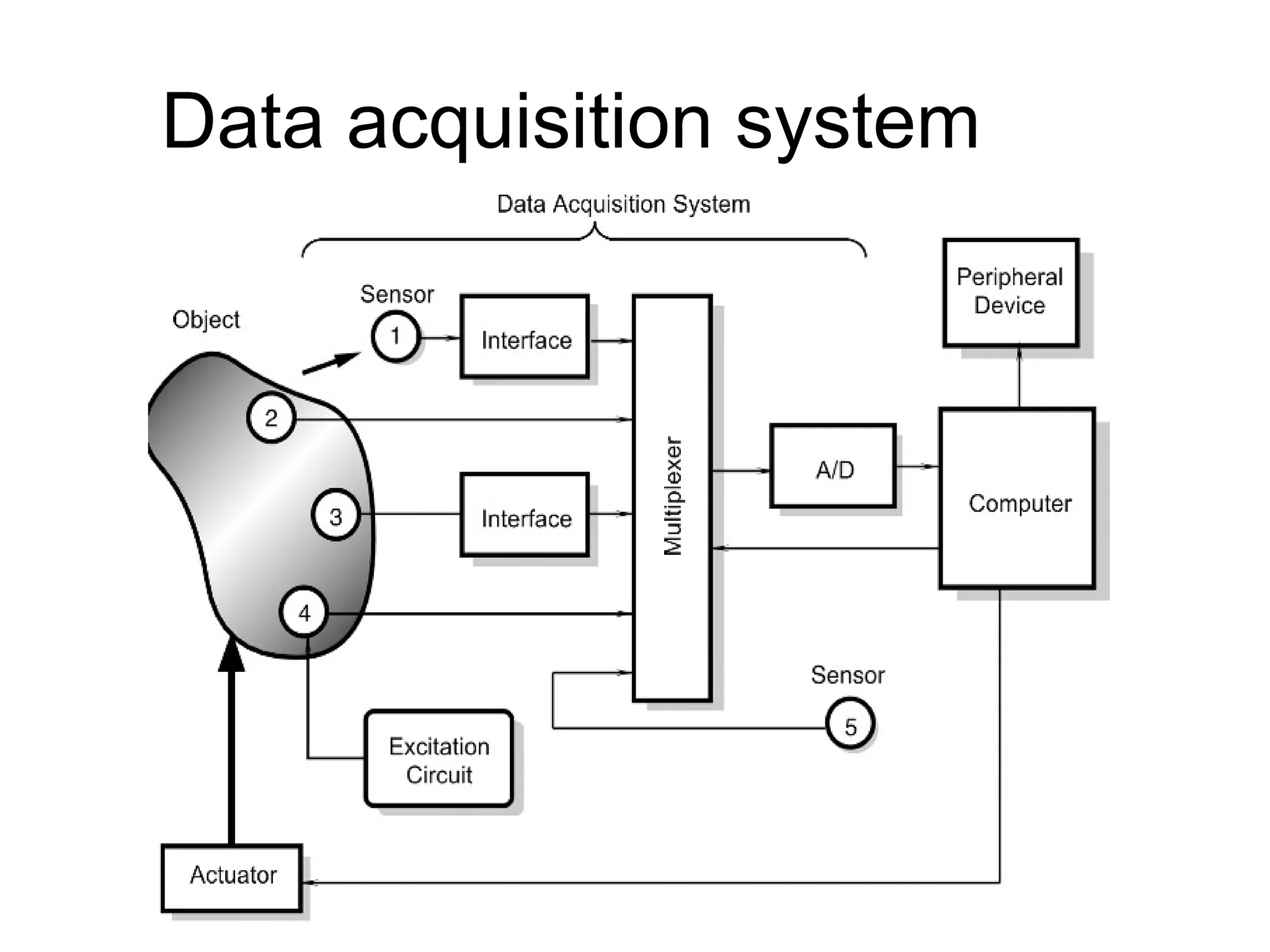
Cont.…
A DAQ system
consistsof sensors,
DAQ measurement
hardware, and a
computer with
programmable
software. Compared
to traditional
measurement
systems, PC-based
DAQ systems
exploit the
processing power,
productivity,
display, and
connectivity
capabilities of
industry-standard
computers
providing a more
powerful, flexible,
and cost-effective
measurement