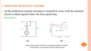
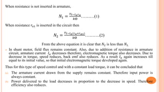
DC machines can achieve wide range speed control through three main methods - armature resistance control to vary speed below base speed, field flux control to vary speed above base speed, and armature voltage control using systems like Ward-Leonard which combine armature and field control to achieve the widest speed range from below to above base speed. Controlled rectifiers and series-parallel configurations are also used to vary armature voltage for smooth speed regulation.
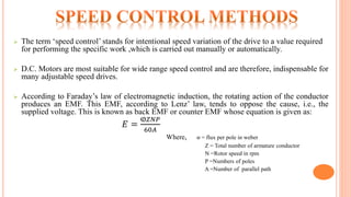
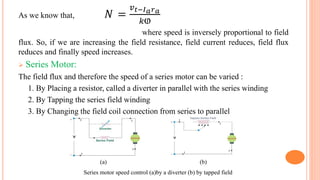
![ Series Motor:
(a) (b)
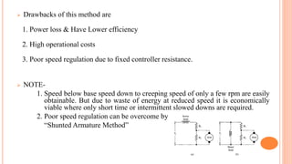
For the wide range of speed ,this method is usually carried out. Similar is the case as earlier
discussed in shunt motor, it has the speed below base speed.
Applications: Series motor driving Cranes, Hoists, Trains etc.
NOTE: In both the motors, field flux remains constant where armature current is maintained
equal to its rated value. So Armature circuit resistance method is usually referred to as a
Constant Torque[𝑘ⱷ𝐼 𝑎] drive method.
Series motor speed control by varying the armature resistance
(a) Schematic circuit diagram and (b) Speed torque](https://image.slidesharecdn.com/praveenkumar-171218064309/85/Speed-Control-Of-DC-Motor-11-320.jpg)
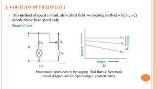
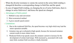
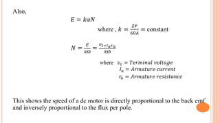
![(a) Schematic diagram of Ward-Leonard
system of speed control
(b) Torque-speed and Power-speed
characteristics of Ward-Leonard system
Speeds from the lowest possible speed up to base speed are obtained by G output
voltage, with constant motor field flux. Since the speed control is carried out with
rated current 𝐼 𝑎 & with constant motor field flux ⱷ, A constant torque[𝑘ⱷ𝐼 𝑎] and
variation of Power[𝑇𝑁] to the speed is obtained. Thus Constant Torque & Variable
Power drive is obtained up to base speed.](https://image.slidesharecdn.com/praveenkumar-171218064309/85/Speed-Control-Of-DC-Motor-16-320.jpg)
![ [1]. Electrical Machinery By Dr. P.S. Bimbhra
[2]. Electrical Machines By Ashfaq Husain
[3] Electric Machinery Fundamentals By Stephen J. Chapman](https://image.slidesharecdn.com/praveenkumar-171218064309/85/Speed-Control-Of-DC-Motor-22-320.jpg)


![[Deck] What's New in Spark-Iceberg Integration via DSV2.pptx](https://cdn.slidesharecdn.com/ss_thumbnails/deckwhatsnewinspark-icebergintegrationviadsv2-260210005337-25955b12-thumbnail.jpg?width=640&height=640&fit=bounds)


