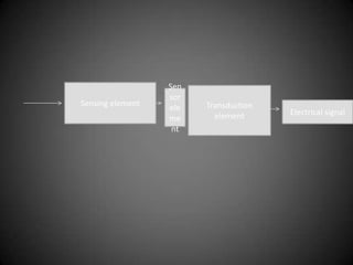
TRANSDUCER
• Transducer is a device that receives energy in
  one system and transmits to other in a
  different form.
• Will generate signal related to the input
  received which energizes the transducer.
• The output may be mechanical or electrical
• The energy transmitted may be mechanical or
  electrical or acoustical.
• There are two types- electrical and mechanical
Sen
                  sor
Sensing element         Transduction
                  ele
                          element      Electrical signal
                  me
                   nt
Parameters of transducer
• Linearity – relationship between input and
  output must be linear.
• Dynamic range –should be wide.
• Physical size –minimum weight and volume.
• repeatability- i/p and o/p relationship must be
  predictable.
• Accuracy – ideal value of the variable being
  measured.
• Physical size – have minimal weight and
ELECTRICAL TRANSDUCER
• It converts non electrical signal into electrical
  signal.
• The output can be easily used for transmission
  and storage.
• Effects of friction are minimized.
• Electrical amplification and attenuation can be
  easily done.
• Can be controlled with a very small power
  level.
• Electrical Transducer is a sensing device
  by which a physical , mechanical or optical
  quantity to be measured is transformed
  directly into electrical voltage or current
  proportional to the input.
• Mechanical Transducers respond to change in
  physical conditions and give output in
  different form.
• The output can be modified.
• The output can be recorded at a distance from
  the sensing medium.
• It can be classified into two major categories
• Active
• Passive
• Active transducer generates electrical signal in
  response to input
• Does not require any power source for operation
• Example- piezoelectric cells
• Photovoltaic cells
• Passive transducers depend on the change in
  electrical parameters such as R,L,C.
• Examples- strain gauge, thermistors
• Electrical transducers contains sensing
  element and transduction element.
SELECTION OF TRANSDUCER
• 1.loading effect- should have a minimum
  loading effect to keep the errors to minimum.
• Nature of measurement
• Environmental conditions pressure ,shock, size
  and mounting restrictions
• Operating range
• Electrical parameters
RESISTIVE TRANSDUCER
• Material in which the resistance due to a
  change in some physical phenomenon.
• Potentiometer-it consists of a resistance
  element provided with a sliding contact called
  wiper.
• Movement can be in rotational and
  translational or combination of both.
• It is a method of converting mechanical
  displacement into electrical output.
• The electrical output is proportional to
  movement.
• Based on the position of the pot the resistor
  will be added.
ADVANTAGES
• They are inexpensive
• Simple to operate.
• Disadvantages-large force is required to move
  sliding contact
• Can generate noise and misaligned.
Resistance pressure transducer
• It is based on the fact that a change in pressure
  results in a resistance change in sensing
  element.
• The element made by the pressure change is
  made to cause a change in resistance.
• The change of resistance can be made part of a
  bridge circuit
• Fluid or gas whose pressure is to be measured
  to pass through pressure sensitive element.
• Causes mechanical displacement.
• Output is proportional to the displacement.
• Bellows is a sensitive element thin walled
  cylindrical shells.
• Materials used are phosphor bronze.
Strain gauge

• It is an example of passive transducer.
• It uses the variation in electrical resistance in
  wires to sense the strain produced by the
  force on the wires.
• If a metal conductor is stretched its resistance
  changes.
• It is mounted on material which is subjected
  to force.
Resistance wire gauge
• Unbounded resistance wire gauge and bonded
  strain gauge
• In first one a wire is stretched between two
  points in an insulating medium
• The diameter is 25 micro meter.
• It is connected to bridge circuit.
• When external load is applied resistance
  changes and causes unbalance in bridge
  circuit
• In bonded strain gauge it's looped back and
  forth on a carrier
• The wire is covered on top with a thin material
• A stress tends to change the length of wire
  and length increases.
• The strain gauge is normally used in bridge
  arrangement.
• Only one of the gauge is active producing the
  output proportional to force.
Types of strain gauge
• The rosette type is having three or four arms.
• It is used when the direction of force is
  unknown
• Gauge elements are arranged in either 45
  degree or 60.
• Torque and helical type are the other type of
  gauge transducer.
• Advantages.
• It should have a high value of gauge factor.
• The ressitance should be as high as possible.
• It should not have hysteresis effect,.
• The variation in resistance should be having
  linear characteristics.
Foil strain gauge
• The strain is detected using am metal foil.
• The metals and alloys used are nichrome
  ,constantan etc.
• It is based on peizo resistive effect.
• They can be fabricated on large scale and at
  any shape.
• It can be mounted on remote and places and
  curved surfaces.
• The resistance values is generally 50 and 1000.
Semiconductor strain guage
• These are used when high value of gauge
  factor is necessary.
• They have gauge factor 50 times as high as
  wire strain gauges.
• Materials used are germanium and silicon.
• It consists of strain material and leads that are
  placed in a box.
• Semiconductor wafer which have thickness of
  0.05 mm are used.
advantages
• It can be used to measure very small strains.
• Very small in size ranging from .7 to 7.0mm
• But they are more expensive and linearity of
  these type is poor.
RESISTANCE thermometer
• The resistance of a conductor changes when its
  temperature is changed.
• It is used to measure the resistance in terms of
  temperature.
• Its main part is the sensing element.
• It exhibits a relatively large resistance change
  with change in temperature.
• Platinum, nickel, copper are the metals most
  commonly used to measure temperature.
• The measurement is very accurate.
• It has a lot of flexibility with regard to choice
  of measuring equipment.
• Stability of performance over long period of
  time.
• But they have higher cost need for bridge
  circuit and power source.
INDUCTIVE TRANSDUCER
• IT IS A DEVICE WHICH converts physical motion
  into change in inductance
• It works on one of the following methods
• Variation of self inductance
• And variation of mutual inductancce.
• It is mainly used for the measuremnt of
  diaplacement.
• It is arranged to cause the variations in any one of
  the variables
• Number of turns
• Geometric configuration.
Variable reluctance type
              transducer
• It consists of a coil or winding wound on a a
  ferromagnetic core.
• The displacement which is to be measured is
  applied to ferromagnetic target.
• The target does not have any contact with he
  core on which it is mounted.
• When the target is near the core length is
  small and therefore the reluctance is large.
• When the target is away from the core the
  reluctance is large resulting in smaller self
  inductance value.
• Thus the inductance of the coil is a function of
  displacement.
• In variable reluctance bridge a saperate col is
  wound on each outside leg of E core and iron
  bar is pivoted on center leg.
• The moving member is attached on one end
  of the iron bar.
• It is balanced only when the inductance of the
  two transducer coils are equal
Thermistor
• Thermistor is as a semiconductor component which
  made by pure oxides of iron, cobalt, nickel,
  magnesium, with other material.
• It has negative temp coefficient.
• It is mainly used for temperature measurement .
• It is found in different shapes like disc type, rod type
  ,washer type.
• Disc type – 10mm diameter
• It is mainly used for temperature control.
• Thermistors can be connected in series or parallel
  combination
• It is also used in regulator circuits , memory units.
Differential output transducer
• It consists of a coil which is divided into to
  parts.
• In response to displacement the inductance of
  one part increases form L to delta and other
  part from L-deltaL
• The output represents a change of self
  inductance due to change of response.
LVDT
• The transformer consists of single primary
  winding P1 and two secondary windings s1
  and S2 wound on hollow cylindrical former.
• The primary is connected to ac source.
• The displacement to be measured is applied
  to arm attached to the soft iron core.
• When the core is its normal position equal
  voltages are induced in the two secondary
  windings.
• If the core is moved to the left of the null
  position more flux links with windings s1 AND
  LESS WITH WINDINGS S2.
• Hence output voltage es1 of the secondary
  winding s1 is greater than es2.
• If the core is moved to right position the flux
  linking with winding s2 becomes greater than
  the linked winding S1.
• The Rotational Variable Differential Transformer
  (RVDT) is used to measure rotational angles and
  operates under the same principles as the LVDT
  sensor.
• Whereas the LVDT uses a cylindrical iron core, the
  RVDT uses a rotary ferromagnetic core. A schematic
  is shown below.
• Relative low cost due to its popularity.
    - Solid and robust, capable of working in a wide
  variety of environments.
    - No friction resistance, since the iron core does not
  contact the transformer coils, resulting in an very long
  service life.
    - High signal to noise ratio and low output
  impedance.
    - Negligible hysteresis.

• The core must be in contact (directly or indirectly) with
  the measured surface which is not always possible or
  desirable.
•

Transducer

  • 1.
  • 2.
    • Transducer isa device that receives energy in one system and transmits to other in a different form. • Will generate signal related to the input received which energizes the transducer. • The output may be mechanical or electrical • The energy transmitted may be mechanical or electrical or acoustical. • There are two types- electrical and mechanical
  • 3.
    Sen sor Sensing element Transduction ele element Electrical signal me nt
  • 4.
    Parameters of transducer •Linearity – relationship between input and output must be linear. • Dynamic range –should be wide. • Physical size –minimum weight and volume. • repeatability- i/p and o/p relationship must be predictable. • Accuracy – ideal value of the variable being measured. • Physical size – have minimal weight and
  • 5.
    ELECTRICAL TRANSDUCER • Itconverts non electrical signal into electrical signal. • The output can be easily used for transmission and storage. • Effects of friction are minimized. • Electrical amplification and attenuation can be easily done. • Can be controlled with a very small power level.
  • 6.
    • Electrical Transduceris a sensing device by which a physical , mechanical or optical quantity to be measured is transformed directly into electrical voltage or current proportional to the input. • Mechanical Transducers respond to change in physical conditions and give output in different form.
  • 7.
    • The outputcan be modified. • The output can be recorded at a distance from the sensing medium. • It can be classified into two major categories • Active • Passive • Active transducer generates electrical signal in response to input • Does not require any power source for operation
  • 8.
    • Example- piezoelectriccells • Photovoltaic cells • Passive transducers depend on the change in electrical parameters such as R,L,C. • Examples- strain gauge, thermistors • Electrical transducers contains sensing element and transduction element.
  • 9.
    SELECTION OF TRANSDUCER •1.loading effect- should have a minimum loading effect to keep the errors to minimum. • Nature of measurement • Environmental conditions pressure ,shock, size and mounting restrictions • Operating range • Electrical parameters
  • 10.
    RESISTIVE TRANSDUCER • Materialin which the resistance due to a change in some physical phenomenon. • Potentiometer-it consists of a resistance element provided with a sliding contact called wiper. • Movement can be in rotational and translational or combination of both.
  • 11.
    • It isa method of converting mechanical displacement into electrical output. • The electrical output is proportional to movement. • Based on the position of the pot the resistor will be added.
  • 15.
    ADVANTAGES • They areinexpensive • Simple to operate. • Disadvantages-large force is required to move sliding contact • Can generate noise and misaligned.
  • 16.
    Resistance pressure transducer •It is based on the fact that a change in pressure results in a resistance change in sensing element. • The element made by the pressure change is made to cause a change in resistance. • The change of resistance can be made part of a bridge circuit
  • 17.
    • Fluid orgas whose pressure is to be measured to pass through pressure sensitive element. • Causes mechanical displacement. • Output is proportional to the displacement. • Bellows is a sensitive element thin walled cylindrical shells. • Materials used are phosphor bronze.
  • 20.
    Strain gauge • Itis an example of passive transducer. • It uses the variation in electrical resistance in wires to sense the strain produced by the force on the wires. • If a metal conductor is stretched its resistance changes. • It is mounted on material which is subjected to force.
  • 21.
    Resistance wire gauge •Unbounded resistance wire gauge and bonded strain gauge • In first one a wire is stretched between two points in an insulating medium • The diameter is 25 micro meter. • It is connected to bridge circuit. • When external load is applied resistance changes and causes unbalance in bridge circuit
  • 23.
    • In bondedstrain gauge it's looped back and forth on a carrier • The wire is covered on top with a thin material • A stress tends to change the length of wire and length increases. • The strain gauge is normally used in bridge arrangement. • Only one of the gauge is active producing the output proportional to force.
  • 24.
    Types of straingauge • The rosette type is having three or four arms. • It is used when the direction of force is unknown • Gauge elements are arranged in either 45 degree or 60. • Torque and helical type are the other type of gauge transducer. • Advantages. • It should have a high value of gauge factor. • The ressitance should be as high as possible.
  • 25.
    • It shouldnot have hysteresis effect,. • The variation in resistance should be having linear characteristics.
  • 30.
    Foil strain gauge •The strain is detected using am metal foil. • The metals and alloys used are nichrome ,constantan etc. • It is based on peizo resistive effect. • They can be fabricated on large scale and at any shape. • It can be mounted on remote and places and curved surfaces. • The resistance values is generally 50 and 1000.
  • 33.
    Semiconductor strain guage •These are used when high value of gauge factor is necessary. • They have gauge factor 50 times as high as wire strain gauges. • Materials used are germanium and silicon. • It consists of strain material and leads that are placed in a box. • Semiconductor wafer which have thickness of 0.05 mm are used.
  • 34.
    advantages • It canbe used to measure very small strains. • Very small in size ranging from .7 to 7.0mm • But they are more expensive and linearity of these type is poor.
  • 35.
    RESISTANCE thermometer • Theresistance of a conductor changes when its temperature is changed. • It is used to measure the resistance in terms of temperature. • Its main part is the sensing element. • It exhibits a relatively large resistance change with change in temperature. • Platinum, nickel, copper are the metals most commonly used to measure temperature.
  • 37.
    • The measurementis very accurate. • It has a lot of flexibility with regard to choice of measuring equipment. • Stability of performance over long period of time. • But they have higher cost need for bridge circuit and power source.
  • 38.
    INDUCTIVE TRANSDUCER • ITIS A DEVICE WHICH converts physical motion into change in inductance • It works on one of the following methods • Variation of self inductance • And variation of mutual inductancce. • It is mainly used for the measuremnt of diaplacement. • It is arranged to cause the variations in any one of the variables • Number of turns • Geometric configuration.
  • 41.
    Variable reluctance type transducer • It consists of a coil or winding wound on a a ferromagnetic core. • The displacement which is to be measured is applied to ferromagnetic target. • The target does not have any contact with he core on which it is mounted. • When the target is near the core length is small and therefore the reluctance is large.
  • 42.
    • When thetarget is away from the core the reluctance is large resulting in smaller self inductance value. • Thus the inductance of the coil is a function of displacement.
  • 44.
    • In variablereluctance bridge a saperate col is wound on each outside leg of E core and iron bar is pivoted on center leg. • The moving member is attached on one end of the iron bar. • It is balanced only when the inductance of the two transducer coils are equal
  • 46.
    Thermistor • Thermistor isas a semiconductor component which made by pure oxides of iron, cobalt, nickel, magnesium, with other material. • It has negative temp coefficient. • It is mainly used for temperature measurement . • It is found in different shapes like disc type, rod type ,washer type. • Disc type – 10mm diameter • It is mainly used for temperature control. • Thermistors can be connected in series or parallel combination • It is also used in regulator circuits , memory units.
  • 48.
    Differential output transducer •It consists of a coil which is divided into to parts. • In response to displacement the inductance of one part increases form L to delta and other part from L-deltaL
  • 49.
    • The outputrepresents a change of self inductance due to change of response.
  • 50.
    LVDT • The transformerconsists of single primary winding P1 and two secondary windings s1 and S2 wound on hollow cylindrical former. • The primary is connected to ac source. • The displacement to be measured is applied to arm attached to the soft iron core. • When the core is its normal position equal voltages are induced in the two secondary windings.
  • 51.
    • If thecore is moved to the left of the null position more flux links with windings s1 AND LESS WITH WINDINGS S2. • Hence output voltage es1 of the secondary winding s1 is greater than es2. • If the core is moved to right position the flux linking with winding s2 becomes greater than the linked winding S1.
  • 54.
    • The RotationalVariable Differential Transformer (RVDT) is used to measure rotational angles and operates under the same principles as the LVDT sensor. • Whereas the LVDT uses a cylindrical iron core, the RVDT uses a rotary ferromagnetic core. A schematic is shown below.
  • 56.
    • Relative lowcost due to its popularity. - Solid and robust, capable of working in a wide variety of environments. - No friction resistance, since the iron core does not contact the transformer coils, resulting in an very long service life. - High signal to noise ratio and low output impedance. - Negligible hysteresis. • The core must be in contact (directly or indirectly) with the measured surface which is not always possible or desirable. •