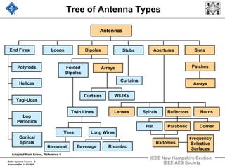
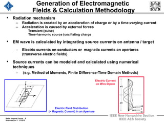
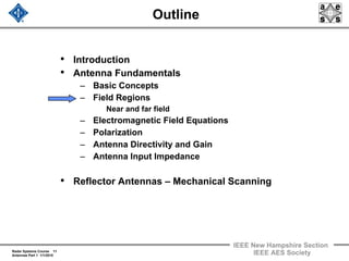
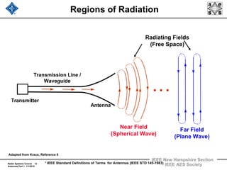
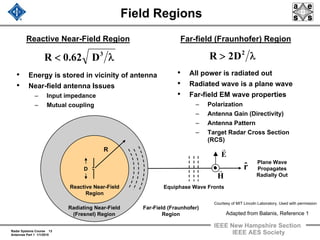
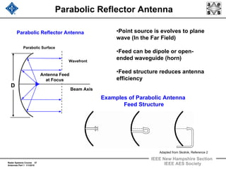
This document provides an overview of radar antennas and scanning techniques. It begins with introductions to basic antenna concepts such as near and far field regions, electromagnetic field equations, polarization, and antenna gain. It then discusses reflector antennas, which use mechanical scanning to direct the antenna beam. The document outlines additional topics that will be covered, including phased array antennas, frequency scanning, and hybrid scanning methods. The goal is to provide an introduction to different types of radar antennas and how they are used to direct electromagnetic energy.
Tutorial Content
This tutorial provides a broad-based discussion of radar system, covering the following topics:
-Introduction to Radars in Military and Commercial Applications
-Radar System Block Diagram
-Radar Antennas (slotted waveguide array, planar array), Transmitter (magnetron, solid-state), Receiver, Pedestal and Radome
-Plot Extraction, Tracking Algorithms and Display
-Radar Range Equation, Detection Performance
-Wave Propagation and Radar Cross Section
-Emerging and Advanced Radar Systems (phased-array, multi-beam, multi-mode, FMCW, solid-state)
In the discussion, practical systems, technical specifications and data will be used to enhance learning.In addition, simulation results will also be used to present findings.
The objective of the tutorial session is to equip participants with solid understanding of radar systems for system level applications and prepare them for advanced and professional radar courses, projects and research.
This tutorial is designed and developed based on the following references:
[1] G. W. Stimson, Introduction to Airborne Radar Second Edition, Scitech Publishing, 1998.
[2] L. V. Blake, A Guide to Basic Pulse-Radar Maximum-Range Calculation, NRL Report 6930, 1969.
[3] K. H. Lee, Radar Systems for Nanyang Technological University, TBSS, 2014.
Radars are very complex electronic and electromagnetic systems. Often they are
complex mechanical systems as well. Radar systems are composed of many different
subsystems, which themselves are composed of many different components. There is a great
diversity in the design of radar systems based on purpose, but the fundamental operation and
main set of subsystems is the same.
A digital revisitation_of_analog_beamforming_techniques - aiaaicssc2013_lisiMarco Lisi
"A Digital Revisitation of Analog Beam Forming Techniques", by P. Angeletti and M.Lisi: presentation at the 19th Ka and 31st AIAA ICSSC Joint Conference, Florence, October 2013
Design and simulation result of various spiral antennas.
Spiral antennas belong to the class of "frequency independent" antennas; these antennas are characterized as having a very large bandwidth. Spiral antennas are travelling wave structures and are well-known for their wideband performance. A bandwidth of 5:1 or 10:1 is easily obtained and a stable input impedance is achieved through a self-complementary geometry. This wideband characteristic of the spiral antenna makes it an attractive choice where a single antenna is required to send / receive over multiple channels. Spiral antennas are usually circularly polarized. The spiral antenna's radiation pattern typically has a peak radiation direction perpendicular to the plane of the spiral (broadside radiation). The Half-Power Beamwidth (HPBW) is approximately 70-90 degrees.
Spiral antennas are widely used in the defense industry for sensing applications, where very wideband antennas that do not take up much space are needed. Spiral antenna arrays are used in military aircraft in the 1-18 GHz range. Other applications of spiral antennas include GPS, where it is advantageous to have RHCP (right hand circularly polarized) antennas.
There are several kind of spiral antennas . An Archimedean spiral made of two equal lengths of coaxial cable seems to be the easiest circularly polarized antenna to make that'll cover a broad range.
Welcome to WIPAC Monthly the magazine brought to you by the LinkedIn Group Water Industry Process Automation & Control.
In this month's edition, along with this month's industry news to celebrate the 13 years since the group was created we have articles including
A case study of the used of Advanced Process Control at the Wastewater Treatment works at Lleida in Spain
A look back on an article on smart wastewater networks in order to see how the industry has measured up in the interim around the adoption of Digital Transformation in the Water Industry.
Using recycled concrete aggregates (RCA) for pavements is crucial to achieving sustainability. Implementing RCA for new pavement can minimize carbon footprint, conserve natural resources, reduce harmful emissions, and lower life cycle costs. Compared to natural aggregate (NA), RCA pavement has fewer comprehensive studies and sustainability assessments.
6th International Conference on Machine Learning & Applications (CMLA 2024)ClaraZara1
6th International Conference on Machine Learning & Applications (CMLA 2024) will provide an excellent international forum for sharing knowledge and results in theory, methodology and applications of on Machine Learning & Applications.
Industrial Training at Shahjalal Fertilizer Company Limited (SFCL)MdTanvirMahtab2
This presentation is about the working procedure of Shahjalal Fertilizer Company Limited (SFCL). A Govt. owned Company of Bangladesh Chemical Industries Corporation under Ministry of Industries.
NUMERICAL SIMULATIONS OF HEAT AND MASS TRANSFER IN CONDENSING HEAT EXCHANGERS...ssuser7dcef0
Power plants release a large amount of water vapor into the
atmosphere through the stack. The flue gas can be a potential
source for obtaining much needed cooling water for a power
plant. If a power plant could recover and reuse a portion of this
moisture, it could reduce its total cooling water intake
requirement. One of the most practical way to recover water
from flue gas is to use a condensing heat exchanger. The power
plant could also recover latent heat due to condensation as well
as sensible heat due to lowering the flue gas exit temperature.
Additionally, harmful acids released from the stack can be
reduced in a condensing heat exchanger by acid condensation. reduced in a condensing heat exchanger by acid condensation.
Condensation of vapors in flue gas is a complicated
phenomenon since heat and mass transfer of water vapor and
various acids simultaneously occur in the presence of noncondensable
gases such as nitrogen and oxygen. Design of a
condenser depends on the knowledge and understanding of the
heat and mass transfer processes. A computer program for
numerical simulations of water (H2O) and sulfuric acid (H2SO4)
condensation in a flue gas condensing heat exchanger was
developed using MATLAB. Governing equations based on
mass and energy balances for the system were derived to
predict variables such as flue gas exit temperature, cooling
water outlet temperature, mole fraction and condensation rates
of water and sulfuric acid vapors. The equations were solved
using an iterative solution technique with calculations of heat
and mass transfer coefficients and physical properties.
Water billing management system project report.pdfKamal Acharya
Our project entitled “Water Billing Management System” aims is to generate Water bill with all the charges and penalty. Manual system that is employed is extremely laborious and quite inadequate. It only makes the process more difficult and hard.
The aim of our project is to develop a system that is meant to partially computerize the work performed in the Water Board like generating monthly Water bill, record of consuming unit of water, store record of the customer and previous unpaid record.
We used HTML/PHP as front end and MYSQL as back end for developing our project. HTML is primarily a visual design environment. We can create a android application by designing the form and that make up the user interface. Adding android application code to the form and the objects such as buttons and text boxes on them and adding any required support code in additional modular.
MySQL is free open source database that facilitates the effective management of the databases by connecting them to the software. It is a stable ,reliable and the powerful solution with the advanced features and advantages which are as follows: Data Security.MySQL is free open source database that facilitates the effective management of the databases by connecting them to the software.
Harnessing WebAssembly for Real-time Stateless Streaming PipelinesChristina Lin
Traditionally, dealing with real-time data pipelines has involved significant overhead, even for straightforward tasks like data transformation or masking. However, in this talk, we’ll venture into the dynamic realm of WebAssembly (WASM) and discover how it can revolutionize the creation of stateless streaming pipelines within a Kafka (Redpanda) broker. These pipelines are adept at managing low-latency, high-data-volume scenarios.
Saudi Arabia stands as a titan in the global energy landscape, renowned for its abundant oil and gas resources. It's the largest exporter of petroleum and holds some of the world's most significant reserves. Let's delve into the top 10 oil and gas projects shaping Saudi Arabia's energy future in 2024.
We have compiled the most important slides from each speaker's presentation. This year’s compilation, available for free, captures the key insights and contributions shared during the DfMAy 2024 conference.
Forklift Classes Overview by Intella PartsIntella Parts
Discover the different forklift classes and their specific applications. Learn how to choose the right forklift for your needs to ensure safety, efficiency, and compliance in your operations.
For more technical information, visit our website https://intellaparts.com
Online aptitude test management system project report.pdfKamal Acharya
The purpose of on-line aptitude test system is to take online test in an efficient manner and no time wasting for checking the paper. The main objective of on-line aptitude test system is to efficiently evaluate the candidate thoroughly through a fully automated system that not only saves lot of time but also gives fast results. For students they give papers according to their convenience and time and there is no need of using extra thing like paper, pen etc. This can be used in educational institutions as well as in corporate world. Can be used anywhere any time as it is a web based application (user Location doesn’t matter). No restriction that examiner has to be present when the candidate takes the test.
Every time when lecturers/professors need to conduct examinations they have to sit down think about the questions and then create a whole new set of questions for each and every exam. In some cases the professor may want to give an open book online exam that is the student can take the exam any time anywhere, but the student might have to answer the questions in a limited time period. The professor may want to change the sequence of questions for every student. The problem that a student has is whenever a date for the exam is declared the student has to take it and there is no way he can take it at some other time. This project will create an interface for the examiner to create and store questions in a repository. It will also create an interface for the student to take examinations at his convenience and the questions and/or exams may be timed. Thereby creating an application which can be used by examiners and examinee’s simultaneously.
Examination System is very useful for Teachers/Professors. As in the teaching profession, you are responsible for writing question papers. In the conventional method, you write the question paper on paper, keep question papers separate from answers and all this information you have to keep in a locker to avoid unauthorized access. Using the Examination System you can create a question paper and everything will be written to a single exam file in encrypted format. You can set the General and Administrator password to avoid unauthorized access to your question paper. Every time you start the examination, the program shuffles all the questions and selects them randomly from the database, which reduces the chances of memorizing the questions.
RAT: Retrieval Augmented Thoughts Elicit Context-Aware Reasoning in Long-Hori...
Radar 2009 a 8 antennas 1
1. IEEE New Hampshire Section
Radar Systems Course 1
Antennas Part 1 1/1/2010 IEEE AES Society
Radar Systems Engineering
Lecture 8
Antennas
Part 1 - Basics and Mechanical Scanning
Dr. Robert M. O’Donnell
IEEE New Hampshire Section
Guest Lecturer
2. Radar Systems Course 2
Antennas Part 1 1/1/2010
IEEE New Hampshire Section
IEEE AES Society
Block Diagram of Radar System
Transmitter
Waveform
Generation
Power
Amplifier
T / R
Switch
Antenna
Propagation
Medium
Target
Radar
Cross
Section
Photo Image
Courtesy of US Air Force
Used with permission.
Pulse
Compression
Receiver
Clutter Rejection
(Doppler Filtering)
A / D
Converter
General Purpose Computer
Tracking
Data
Recording
Parameter
Estimation
Detection
Signal Processor Computer
Thresholding
User Displays and Radar Control
3. Radar Systems Course 3
Antennas Part 1 1/1/2010
IEEE New Hampshire Section
IEEE AES Society
Antenna Functions and the Radar Equation
• “Means for radiating or receiving radio waves”*
– A radiated electromagnetic wave consists of electric and
magnetic fields which jointly satisfy Maxwell’s Equations
• Direct microwave radiation in desired directions, suppress
in others
• Designed for optimum gain (directivity) and minimum loss
of energy during transmit or receive
Pt G2 λ2 σ
(4 π )3 R4 k Ts Bn L
S / N =
Track
Radar
Equation
Pav Ae ts σ
4 π Ω R4 k Ts L
S / N =
Search
Radar
Equation
G = Gain
Ae = Effective Area
Ts = System Noise
Temperature
L = Losses
This
Lecture
Radar
Equation
Lecture
* IEEE Standard Definitions of Terms for Antennas (IEEE STD 145-1983)
4. Radar Systems Course 4
Antennas Part 1 1/1/2010
IEEE New Hampshire Section
IEEE AES Society
Radar Antennas Come in Many Sizes
and Shapes
Mechanical Scanning
Antenna Hybrid Mechanical and Frequency
Scanning Antenna
Electronic Scanning
Antenna
Hybrid Mechanical and Frequency
Scanning Antenna
Electronic Scanning
Antenna
Mechanical Scanning
Antenna
Photo
Courtesy
of ITT Corporation
Used with
Permission
Photo Courtesy of Raytheon
Used with Permission
Photo Courtesy of Northrop Grumman
Used with Permission
Courtesy US Dept of Commerce
Courtesy US Army
Courtesy of MIT Lincoln Laboratory, Used with permission
5. Radar Systems Course 5
Antennas Part 1 1/1/2010
IEEE New Hampshire Section
IEEE AES Society
Outline
• Introduction
• Antenna Fundamentals
• Reflector Antennas – Mechanical Scanning
• Phased Array Antennas
• Frequency Scanning of Antennas
• Hybrid Methods of Scanning
• Other Topics
Part
One
Part
Two
6. Radar Systems Course 6
Antennas Part 1 1/1/2010
IEEE New Hampshire Section
IEEE AES Society
Outline
• Introduction
• Antenna Fundamentals
– Basic Concepts
– Field Regions
Near and far field
– Electromagnetic Field Equations
– Polarization
– Antenna Directivity and Gain
– Antenna Input Impedance
• Reflector Antennas – Mechanical Scanning
7. Radar Systems Course 7
Antennas Part 1 1/1/2010
IEEE New Hampshire Section
IEEE AES Society
Tree of Antenna Types
Antennas
Yagi-Udas
Loops Dipoles SlotsAperturesStubs
Helices
Polyrods
End Fires
Log
Periodics
Conical
Spirals
Folded
Dipoles
Long WiresVees
Twin Lines
Arrays
Biconical Beverage Rhombic
W8JKsCurtains
Curtains
Spirals HornsReflectorsLenses
Flat CornerParabolic
Frequency
Selective
Surfaces
Radomes
Patches
Arrays
Adapted from Kraus, Reference 6
8. Radar Systems Course 8
Antennas Part 1 1/1/2010
IEEE New Hampshire Section
IEEE AES Society
Tree of Antenna Types
Antennas
Yagi-Udas
Loops Dipoles SlotsAperturesStubs
Helices
Polyrods
End Fires
Log
Periodics
Conical
Spirals
Folded
Dipoles
Long WiresVees
Twin Lines
Arrays
Biconical Beverage Rhombic
W8JKsCurtains
Curtains
Spirals HornsReflectorsLenses
Flat CornerParabolic
Frequency
Selective
Surfaces
Radomes
Patches
Arrays
Adapted from Kraus, Reference 6
9. Radar Systems Course 9
Antennas Part 1 1/1/2010
IEEE New Hampshire Section
IEEE AES Society
Generation of Electromagnetic
Fields & Calculation Methodology
• Radiation mechanism
– Radiation is created by an acceleration of charge or by a time-varying current
– Acceleration is caused by external forces
Transient (pulse)
Time-harmonic source (oscillating charge
• EM wave is calculated by integrating source currents on antenna / target
– Electric currents on conductors or magnetic currents on apertures
(transverse electric fields)
• Source currents can be modeled and calculated using numerical
techniques
– (e.g. Method of Moments, Finite Difference-Time Domain Methods)
Electric Current
on Wire Dipole
Electric Field Distribution
(~ Magnetic Current) in an Aperture
a
b
y
x
z
λ/4
a/2
a/2
λ/2
λ
3λ/2
2λ
10. Radar Systems Course 10
Antennas Part 1 1/1/2010
IEEE New Hampshire Section
IEEE AES Society
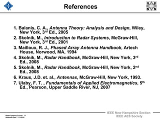
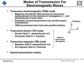
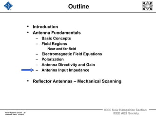
Antenna and Radar Cross Section
Analyses Use “Phasor Representation”
Harmonic Time Variation is assumed :
tj
e ω
[ ]tj
e)z,y,x(E
~
alRe)t;z,y,x(E ω
=
r
α
= j
e)z,y,x(E
~
eˆ)z,y,x(E
~
)t(cos)z,y,x(E
~
eˆ)t;z,y,x(E α+ω=
rInstantaneous
Harmonic Field is :
Calculate Phasor :
Any Time Variation can be Expressed as a
Superposition of Harmonic Solutions by Fourier Analysis
Instantaneous
Electric Field
Phasor
11. Radar Systems Course 11
Antennas Part 1 1/1/2010
IEEE New Hampshire Section
IEEE AES Society
Outline
• Introduction
• Antenna Fundamentals
– Basic Concepts
– Field Regions
Near and far field
– Electromagnetic Field Equations
– Polarization
– Antenna Directivity and Gain
– Antenna Input Impedance
• Reflector Antennas – Mechanical Scanning
12. Radar Systems Course 12
Antennas Part 1 1/1/2010
IEEE New Hampshire Section
IEEE AES Society
Regions of Radiation
* IEEE Standard Definitions of Terms for Antennas (IEEE STD 145-1983)
Transmitter
Transmission Line /
Waveguide
Antenna
Radiating Fields
(Free Space)
Near Field
(Spherical Wave)
Far Field
(Plane Wave)
Adapted from Kraus, Reference 6
13. Radar Systems Course 13
Antennas Part 1 1/1/2010
IEEE New Hampshire Section
IEEE AES Society
Field Regions
• All power is radiated out
• Radiated wave is a plane wave
• Far-field EM wave properties
– Polarization
– Antenna Gain (Directivity)
– Antenna Pattern
– Target Radar Cross Section
(RCS)
• Energy is stored in vicinity of antenna
• Near-field antenna Issues
– Input impedance
– Mutual coupling
λ< 3
D62.0R
Reactive Near-Field Region Far-field (Fraunhofer) Region
λ> 2
D2R
Far-Field (Fraunhofer)
Region
Equiphase Wave Fronts
Plane Wave
Propagates
Radially Out
D
R
Reactive Near-Field
Region
Radiating Near-Field
(Fresnel) Region
rˆ
E
r
H
r
Adapted from Balanis, Reference 1
Courtesy of MIT Lincoln Laboratory, Used with permission
14. Radar Systems Course 14
Antennas Part 1 1/1/2010
IEEE New Hampshire Section
IEEE AES Society
Far-Field EM Wave Properties
r
e
),(E),,r(E
jkr
off
−
φθ≅φθ
rr
ff
jkr
off
Erˆ
1
r
e
),(H),,r(H
rrr
×
η
=φθ≅φθ
−
Ω=
ε
μ
≡η 377
o
o
λπ= 2k
where is the intrinsic impedance of free space
is the wave propagation constant
Standard
Spherical
Coordinate
System
θˆ
φˆ
rˆ
x
z
y
φ
r
θ
Electric Field
Magnetic Field
x
=
z
λ
• In the far-field, a spherical wave can be approximated by a plane
wave
• There are no radial field components in the far field
• The electric and magnetic fields are given by:
y
15. Radar Systems Course 15
Antennas Part 1 1/1/2010
IEEE New Hampshire Section
IEEE AES Society
Outline
• Introduction
• Antenna Fundamentals
– Basic Concepts
– Field Regions
Near and far field
– Electromagnetic Field Equations
– Polarization
– Antenna Directivity and Gain
– Antenna Input Impedance
• Reflector Antennas – Mechanical Scanning
16. Radar Systems Course 16
Antennas Part 1 1/1/2010
IEEE New Hampshire Section
IEEE AES Society
Propagation in Free Space
• Plane wave, free space solution to Maxwell’s Equations:
– No Sources
– Vacuum
– Non-conducting medium
• Most electromagnetic waves are generated from localized
sources and expand into free space as spherical wave.
• In the far field, when the distance from the source great,
they are well approximated by plane waves when they
impinge upon a target and scatter energy back to the radar
( )
( ) )trk(j
)trk(j
eBt,rB
eEt,rE
ω−⋅
→
ω−⋅
→
→→
→→
=
=
o
o
r
r
17. Radar Systems Course 17
Antennas Part 1 1/1/2010
IEEE New Hampshire Section
IEEE AES Society
Modes of Transmission For
Electromagnetic Waves
• Transverse electromagnetic (TEM) mode
– Magnetic and electric field vectors are transverse
(perpendicular) to the direction of propagation, , and
perpendicular to each other
– Examples (coaxial transmission line and free space
transmission,
– TEM transmission lines have two parallel surfaces
• Transverse electric (TE) mode
– Electric field, , perpendicular to
– No electric field in direction
• Transverse magnetic (TM) mode
– Magnetic field, , perpendicular to
– No magnetic field in direction
• Hybrid transmission modes
kˆ
kˆ
kˆ
kˆ
E
r
kˆ
H
r
kˆ
E
r
H
r
TEM Mode
Used for
Rectangular
Waveguides
18. Radar Systems Course 18
Antennas Part 1 1/1/2010
IEEE New Hampshire Section
IEEE AES Society
Pointing Vector – Power Density
• The Poynting Vector, , is defined as:
• It is the power density (power per unit area) carried by an
electromagnetic wave
• Since both and are functions of time, the average
power density is of greater interest, and is given by:
• For a plane wave in a lossless medium
HxES
rrr
≡
S
r
H
r
E
r
( )*
HxERe
2
1
S
rrr
=
AV
2
WE
2
1
S ≡
η
=
rr
o
o
ε
μ
=ηwhere
(W/m2)
19. Radar Systems Course 19
Antennas Part 1 1/1/2010
IEEE New Hampshire Section
IEEE AES Society
Radiation Intensity and Radiated Power
(W/steradian)
• Radiation Intensity = Power radiated per unit solid angle
• Total Power Radiated
∫∫
π π
φθθφθ=
2
0 0
rad ddsin),(UP (W)
where
⎥⎦
⎤
⎢⎣
⎡ φθ+φθ
η
≅
⎥⎦
⎤
⎢⎣
⎡ φθ+φθ
η
≅
φθ
η
=φθ≅φθ
φθ
φθ
2
o
2
o
22
2
2
2
rad
2
),,r(E),,r(E
2
1
),,r(E),,r(E
2
r
),,r(E
2
r
),(Wr),(U
rr
rr
r
r
e
),(E),,r(E
jkr
o
−
φθ=φθ
rr
= far field electric field intensity
φθ E,E = far field electric field components
o
o
ε
μ
=ηand
20. Radar Systems Course 20
Antennas Part 1 1/1/2010
IEEE New Hampshire Section
IEEE AES Society
Outline
• Introduction
• Antenna Fundamentals
– Basic Concepts
– Field Regions
Near and far field
– Electromagnetic Field Equations
– Polarization
– Antenna Directivity and Gain
– Antenna Input Impedance
• Reflector Antennas – Mechanical Scanning
21. Radar Systems Course 21
Antennas Part 1 1/1/2010
IEEE New Hampshire Section
IEEE AES Society
Antenna Polarization
• Defined by behavior of the electric field vector as it propagates in
time as observed along the direction of radiation
• Circular used for weather mitigation
• Horizontal used in long range air search to obtain reinforcement of
direct radiation by ground reflection
φE
rˆ
φE
θE φE
θE
– Linear
–Vertical or Horizontal
–Circular
Two components are equal in amplitude,
and separated in phase by 90 deg
Right-hand (RHCP) is CW above
Left-hand (LHCP) is CCW above
– Elliptical
Major Axis
Minor Axis
Courtesy of MIT Lincoln Laboratory, Used with permission
22. Radar Systems Course 22
Antennas Part 1 1/1/2010
IEEE New Hampshire Section
IEEE AES Society
Polarization
E
Horizontal
Linear
(with respect
to Earth)
• Defined by behavior of the electric field vector as it propagates
in time
(For air surveillance looking upward)
E
(For over-water surveillance)
Vertical
Linear
(with respect
to Earth)
Electromagnetic
Wave Electric Field
Magnetic Field
Courtesy of MIT Lincoln Laboratory, Used with permission
23. Radar Systems Course 23
Antennas Part 1 1/1/2010
IEEE New Hampshire Section
IEEE AES Society
Circular Polarization (CP)
• “Handed-ness” is defined by observation of electric field along
propagation direction
• Used for discrimination, polarization diversity, rain mitigation
Right-Hand
(RHCP)
Propagation Direction
Into Paper
Left-Hand
(LHCP)
Electric
Field
φE
rˆ
φE
θE
Figure by MIT OCW.
24. Radar Systems Course 24
Antennas Part 1 1/1/2010
IEEE New Hampshire Section
IEEE AES Society
Circular Polarization (CP)
• “Handed-ness” is defined by observation of electric field along
propagation direction
• Used for discrimination, polarization diversity, rain mitigation
Right-Hand
(RHCP)
Propagation Direction
Into Paper
Left-Hand
(LHCP)
Electric FieldφE
rˆ
φE
θE
Figure by MIT OCW.
25. Radar Systems Course 25
Antennas Part 1 1/1/2010
IEEE New Hampshire Section
IEEE AES Society
Outline
• Introduction
• Antenna Fundamentals
– Basic Concepts
– Field Regions
Near and far field
– Electromagnetic Field Equations
– Polarization
– Antenna Directivity and Gain
– Antenna Input Impedance
• Reflector Antennas – Mechanical Scanning
26. Radar Systems Course 26
Antennas Part 1 1/1/2010
IEEE New Hampshire Section
IEEE AES Society
Antenna Gain
• Difference between gain and directivity is antenna loss
• “Rules of Thumb”
Radiation
Intensity
from a Sphere
Gain (max)
Gain = Radiation intensity of
antenna in given direction over that
of isotropic source
22
eff A4A4
G
λ
ηπ
=
λ
π
=
AL
D
G =
Maximum Gain
and are the azimuth and
elevation half power beamwidths
BφBθ
BB
000,26
G
φθ
= (degrees) D
65
B
λ
=θ
(degrees)
27. Radar Systems Course 27
Antennas Part 1 1/1/2010
IEEE New Hampshire Section
IEEE AES Society
• Radiation Intensity = = Power radiated / unit solid angle
Directivity & Gain
),(U φθ
radP
),(U4
),(D
φθπ
=φθ (dimensionless)
inP
),(U4
),(G
φθπ
=φθ
• Directivity = Radiation intensity of antenna in given direction
over that of an isotropic source radiating same power
• Gain = Radiation intensity of antenna in given direction over
that of isotropic source radiating available power
– Difference between gain and directivity is antenna loss
– Gain < Directivity
(dimensionless)
• Maximum Gain = Radiation intensity of antenna at peak of beam
22
eff A4A4
G
λ
ηπ
=
λ
π
=
= Area of antenna aperture
= Efficiency of antenna
A
η
28. Radar Systems Course 28
Antennas Part 1 1/1/2010
IEEE New Hampshire Section
IEEE AES Society
Example – Half Wavelength Dipole
Far Field Radiation Intensity
Radiated Power
Gain / Pattern
Effective
Area
( )
⎥
⎥
⎥
⎥
⎦
⎤
⎢
⎢
⎢
⎢
⎣
⎡
θ
⎟
⎠
⎞
⎜
⎝
⎛
θ
π
π
ηθ=θ
−
sin
cos
2
cos
r
e
2
I
jˆE
jkr
off
( )
⎥
⎥
⎥
⎥
⎦
⎤
⎢
⎢
⎢
⎢
⎣
⎡
θ
⎟
⎠
⎞
⎜
⎝
⎛
θ
π
π
φ=θ
−
sin
cos
2
cos
r
e
2
I
jˆH
jkr
off
( )
⎥
⎥
⎥
⎥
⎦
⎤
⎢
⎢
⎢
⎢
⎣
⎡
θ
⎟
⎠
⎞
⎜
⎝
⎛
θ
π
π
η=θ 2
2
2
2
o
sin
cos
2
cos
8
I
U
( )π
π
η= 2C
8
I
P in
2
o
rad
( ) 435.2dy
y
ycos1
2C
2
0
in ≈
−
=π ∫
π
643.1
P
U4
G
in
max
o =
π
=
2o
2
e 13.0
4
D
A λ=
π
λ
=
( ) ( )
⎥
⎥
⎥
⎥
⎦
⎤
⎢
⎢
⎢
⎢
⎣
⎡
θ
⎟
⎠
⎞
⎜
⎝
⎛
θ
π
=
θπ
=θ 2
2
in sin
cos
2
cos
643.1
P
U4
G
Adapted from Balanis, Reference 1, pp182 - 184
Theta θ (deg)
Go = 1.643
= 2.15 dBi
0.5
1
1.5
2
60
120
30
150
0
180
30
150
60
120
90 90
θ θ
Polar Plot
0 45 90 135 180
-30
-20
-10
0
Gain(dBi) Linear Plot
= angle down from z-axisθ
From MIT OCW
29. Radar Systems Course 29
Antennas Part 1 1/1/2010
IEEE New Hampshire Section
IEEE AES Society
Outline
• Introduction
• Antenna Fundamentals
– Basic Concepts
– Field Regions
Near and far field
– Electromagnetic Field Equations
– Polarization
– Antenna Directivity and Gain
– Antenna Input Impedance
• Reflector Antennas – Mechanical Scanning
30. Radar Systems Course 30
Antennas Part 1 1/1/2010
IEEE New Hampshire Section
IEEE AES Society
Antenna Input Impedance
• Antenna can be modeled as an impedance (ratio of voltage to current at
feed port)
– Antenna “resonant” when impedance purely real
– Microwave theory can be applied to equivalent circuit
• Design antenna to maximize power transfer from transmission line
– Reflection of incident power sets up standing wave on line
– Can result in arching under high power conditions
Transmission
Line
Antenna
Γ
Standing Wave
feed
MaxV
MinV
Voltage Reflection
Coefficient
Radiation Resistance
(Power Radiated)
Loss (Ohmic, Dielectric)
Reactance
(Energy Stored)
r
2
orad RI
2
1
P =
Courtesy of MIT Lincoln Laboratory, Used with permission
31. Radar Systems Course 31
Antennas Part 1 1/1/2010
IEEE New Hampshire Section
IEEE AES Society
Antenna Input Impedance
• Antenna can be modeled as an impedance (ratio of voltage to current at
feed port)
– Antenna “resonant” when impedance purely real
– Microwave theory can be applied to equivalent circuit
• Design antenna to maximize power transfer from transmission line
– Reflection of incident power sets up standing wave on line
– Can result in arching under high power conditions
• Usually a 2:1 VSWR is acceptable
Transmission
Line
Antenna
Γ
Standing Wave
feed
Γ−
Γ+
==
1
1
V
V
VSWR
Min
Max Voltage
Standing Wave
Ratio
0=Γ 1VSWR =
All Incident Power
is Delivered
to Antenna
1=Γ ∞→VSWR
All Incident
Power is
Reflected
MaxV
MinV
Courtesy of MIT Lincoln Laboratory, Used with permission
32. Radar Systems Course 32
Antennas Part 1 1/1/2010
IEEE New Hampshire Section
IEEE AES Society
Outline
• Introduction
• Antenna Fundamentals
• Reflector Antennas – Mechanical Scanning
– Basic Antenna (Reflector) Characteristics and
Geometry
– Spillover and Blockage
– Aperture Illumination
– Different Reflector Feeds and Reflector Geometries
33. Radar Systems Course 33
Antennas Part 1 1/1/2010
IEEE New Hampshire Section
IEEE AES Society
Antenna Pattern Characteristics
Aperture diameter D = 5 m
Frequency = 300 MHz
Wavelength = 1 m Gain = 24 dBi
Isotropic Sidelobe Level = 6 dBi
Sidelobe Level = 18 dB
Half-Power Beamwidth = 12 deg
Sidelobe
Level
Half Power (3 dB)
Beamwidth
Isotropic
Sidelobe
Level
AntennaGain(dBi)
Angle (degrees)
-90 -60 -30 0 30 60 90
Antenna Gain vs. Angle
0
-20
20
10
- 10
Parabolic Reflector Antenna
Parabolic Surface
Wavefront
Beam Axis
Antenna Feed
at Focus
D
34. Radar Systems Course 34
Antennas Part 1 1/1/2010
IEEE New Hampshire Section
IEEE AES Society
Parabolic Reflector Antenna
• Reflector antenna design involves a tradeoff between
maximizing dish illumination while limiting spillover and
blockage from feed and its support structure
• Feed antenna choice is critical
Normalized Antenna Gain Pattern
RelativeGain(dB) Angle off Beam Axis (degrees) Figure
By
MIT OCW
Parabolic Reflector Antenna
Parabolic Surface
Wavefront
Beam Axis
Antenna Feed
at Focus
D
35. Radar Systems Course 35
Antennas Part 1 1/1/2010
IEEE New Hampshire Section
IEEE AES Society
Effect of Aperture Size on Gain
Gain
Effective
Area
Rule of Thumb
(Best Case)
2
D
⎟
⎠
⎞
⎜
⎝
⎛
λ
π
=
2
A4
λ
π
≅
2
eA4
λ
π
=
Gain increases as aperture becomes
electrically larger (diameter is a
larger number of wavelengths)
Gain vs Antenna Diameter
MaximumGain(dBi)
Aperture Diameter D (m)
1 3 5 7 9
10
20
30
40
50
λ = 100 cm (300 MHz)
λ = 30 cm (1 GHz)
λ = 10 cm (3 GHz)
Wavelength
Decreases
Parabolic Reflector Antenna
Parabolic Surface
Wavefront
Beam Axis
Antenna Feed
at Focus
D
36. Radar Systems Course 36
Antennas Part 1 1/1/2010
IEEE New Hampshire Section
IEEE AES Society
Effect of Aperture Size on Beamwidth
Beamwidth decreases as aperture becomes electrically larger
(diameter larger number of wavelengths)
Beamwidth (deg)
D
180
π
λ
≅
Antenna Beamwidth
vs. Diameter
Half-PowerBeamwidth(deg)
Aperture Diameter D (m)
1 3 5 7 9
0
8
12
16
20
4
λ = 100 cm (300 MHz)
λ = 30 cm (1 GHz)
λ = 10 cm (3 GHz)
Wavelength
Increases
Parabolic Reflector Antenna
Parabolic Surface
Wavefront
Beam Axis
Antenna Feed
at Focus
D
37. Radar Systems Course 37
Antennas Part 1 1/1/2010
IEEE New Hampshire Section
IEEE AES Society
Parabolic Reflector Antenna
•Point source is evolves to plane
wave (In the Far Field)
•Feed can be dipole or open-
ended waveguide (horn)
•Feed structure reduces antenna
efficiency
Examples of Parabolic Antenna
Feed Structure
Adapted from Skolnik, Reference 2
Parabolic Reflector Antenna
Parabolic Surface
Wavefront
Beam Axis
Antenna Feed
at Focus
D
38. Radar Systems Course 38
Antennas Part 1 1/1/2010
IEEE New Hampshire Section
IEEE AES Society
Different Types of Radar Beams
Pencil Beam
Stacked Beam
Fan Beam
Shaped Beam
Courtesy of Northrop Grumman
Used with PermissionCourtesy of US Air Force
Courtesy of MIT Lincoln Laboratory
Used with permission
Courtesy of MIT Lincoln Laboratory,
Used with permission
39. Radar Systems Course 39
Antennas Part 1 1/1/2010
IEEE New Hampshire Section
IEEE AES Society
Reflector Comparison
Kwajalein Missile Range Example
Operating frequency: 162 MHz (VHF)
Wavelength λ: 1.85 m
Diameter electrical size: 25 λ
Gain: 34 dB
Beamwidth: 2.8 deg
Operating frequency: 35 GHz (Ka)
Wavelength λ: 0.0086 m
Diameter electrical size: 1598 λ
Gain: 70 dB
Beamwidth: 0.00076 deg
ALTAIR
45.7 m diameter
MMW
13.7 m diameter
scale by
1/3
Courtesy of MIT Lincoln Laboratory, Used with permission
40. Radar Systems Course 40
Antennas Part 1 1/1/2010
IEEE New Hampshire Section
IEEE AES Society
Outline
• Introduction
• Antenna Fundamentals
• Reflector Antennas – Mechanical Scanning
– Basic Antenna (Reflector) Characteristics and
Geometry
– Spillover and Blockage
– Aperture Illumination
– Different Reflector Feeds and Reflector Geometries
41. Radar Systems Course 41
Antennas Part 1 1/1/2010
IEEE New Hampshire Section
IEEE AES Society
Antenna Spillover
• Even when the feed is at the exact
focus of the parabolic reflector, a
portion of the emitted energy at the
edge of the beam will not impinge
upon the reflector.
• This is called “beam spillover”
• Tapering the feed illumination can
mitigate this effect
• As will be seen, optimum antenna
performance is a tradeoff between:
– Beam spillover
– Tapering of the aperture illumination
Antenna gain
– Feed blockage
Feed
Reflector
Diffracted
RegionFeed
Spillover
Spillover
Region
Sidelobe
Antenna
Mainlobe
Adapted from Skolnik,
Reference 5
42. Radar Systems Course 42
Antennas Part 1 1/1/2010
IEEE New Hampshire Section
IEEE AES Society
Effect of Aperture Blocking in a
Parabolic Reflector Antenna
Examples of
Aperture Blockage
Feed and its supports
Masts onboard a ship
The effect of aperture blockage can
be approximated by:
– Antenna pattern produced by
shadow of the obstacle
Antenna pattern of
undisturbed aperture
FPS-16
Courtesy of US Air Force
-20 -10 0 10 20
Angle (degrees)
RelativeRadiationIntensity(dB)
0
-10
-20
-30
Shadow
pattern
Pattern with
No Blockage
Pattern with
Blockage
Blockage
Pattern
Adapted
from Skolnik,
Reference 2
43. Radar Systems Course 43
Antennas Part 1 1/1/2010
IEEE New Hampshire Section
IEEE AES Society
Effect of Aperture Blocking in a
Parabolic Reflector Antenna
Examples of
Aperture Blockage
Feed and its supports
Masts onboard a ship
TRADEX
This procedure is possible because of the
linearity of the Fourier transform that relates
the antenna aperture illumination and the
radiation pattern
-20 -10 0 10 20
Angle (degrees)
RelativeRadiationIntensity(dB)
0
-10
-20
-30
Shadow
pattern
Pattern with
No Blockage
Pattern with
Blockage
Blockage
Pattern
Courtesy of MIT Lincoln Laboratory, Used with permission
44. Radar Systems Course 44
Antennas Part 1 1/1/2010
IEEE New Hampshire Section
IEEE AES Society
Examples of Antenna Blockage
USS Abraham Lincoln
SPS-49
SPS-48
USS Theodore Roosevelt
P-15 Flatface
SPG-51
NASA Tracking Radar
Courtesy of US Navy
Courtesy of US Navy
Courtesy of US Navy
Courtesy of US Air Force
Courtesy of NASA
45. Radar Systems Course 45
Antennas Part 1 1/1/2010
IEEE New Hampshire Section
IEEE AES Society
Outline
• Introduction
• Antenna Fundamentals
• Reflector Antennas – Mechanical Scanning
– Basic Antenna (Reflector) Characteristics and
Geometry
– Spillover and Blockage
– Aperture Illumination
– Different Reflector Feeds and Reflector Geometries
46. Radar Systems Course 46
Antennas Part 1 1/1/2010
IEEE New Hampshire Section
IEEE AES Society
Antenna Radiation Pattern
from a Line Source
( ) ( ) dzsin
z
2jexpzAE
2/a
2/a
∫−
⎟
⎠
⎞
⎜
⎝
⎛
φ
λ
π=φ
• The aperture Illumination, , is the current a distance from the
origin (0,0,0), along the axis
• Assumes is in the far field, and
• Note that the electric field is the Inverse Fourier Transform of the
Aperture Illumination.
2/a ( )φE
φ
y
x
z
)2/a(−
Line Source •
z
z( )zA
( )φE λ>>a λ>> /aR 2
Adapted from Skolnik, Reference 1
47. Radar Systems Course 47
Antennas Part 1 1/1/2010
IEEE New Hampshire Section
IEEE AES Society
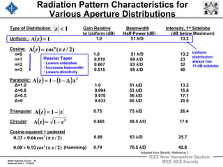
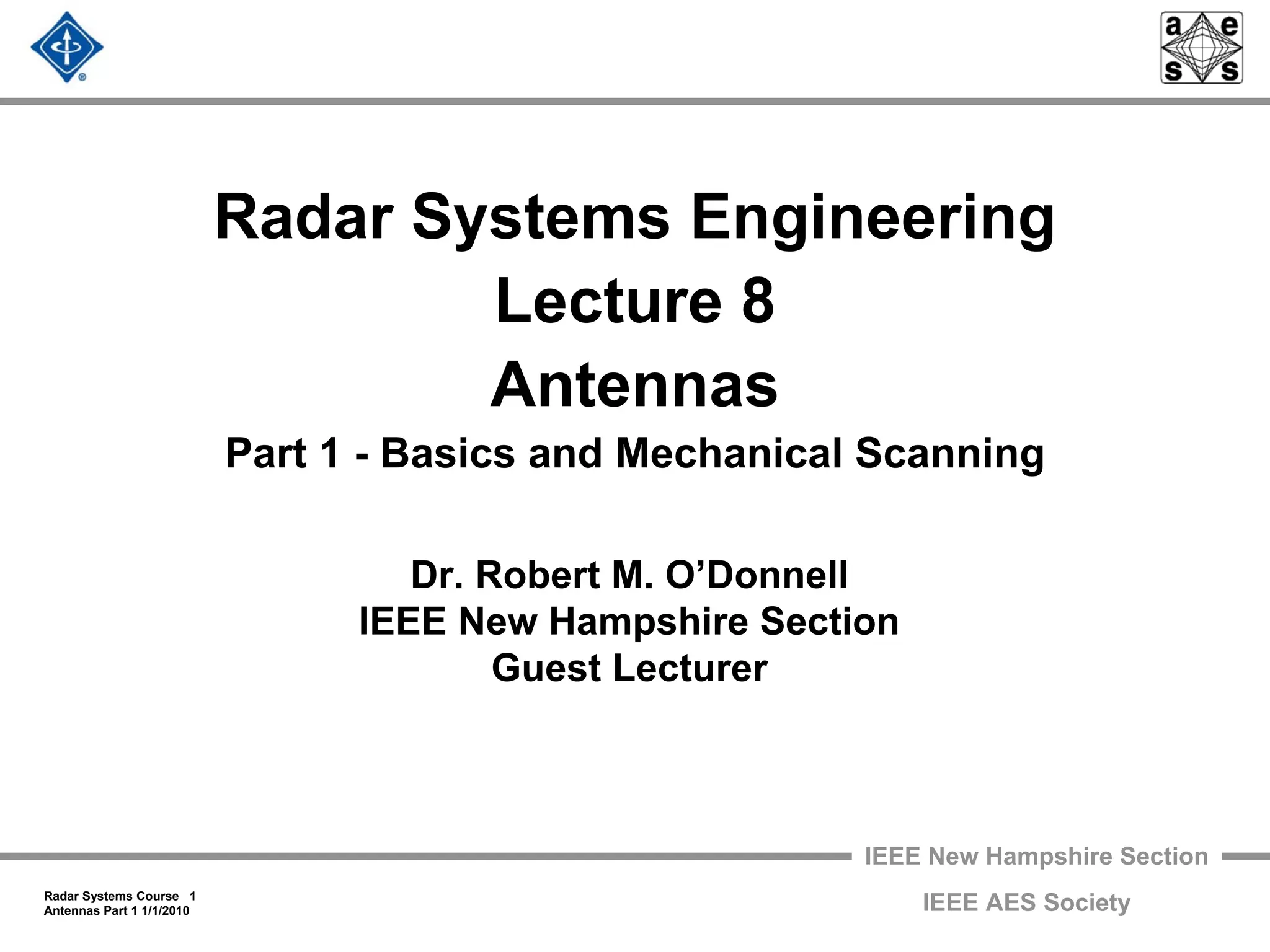
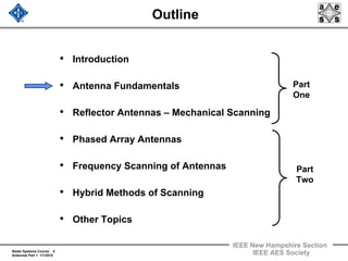
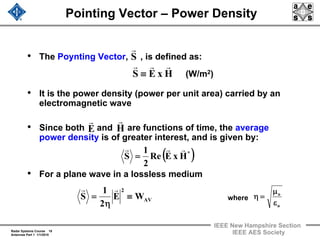
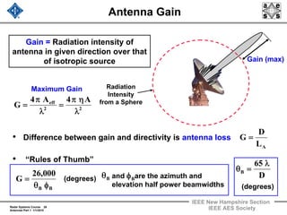
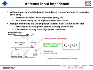
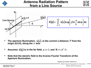
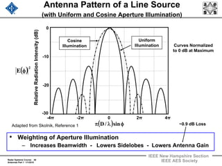
Effect of Source Distribution
on Antenna Pattern of a Line Source
Uniform
Aperture Distribution
Cosine
Aperture Distribution
( ) ( )
( )
( )
( )
( ) φλπ=ψ
⎥
⎦
⎤
⎢
⎣
⎡
π−ψ
π−ψ
+
π+ψ
π+ψπ
=φ
sin/a
2/
2/sin
2/
2/sin
4
E( )
( )[ ]
( )
( ) ( )[ ]
( ) φλπ
φλπ
=φ
φλπ
φλπ
=
⎟
⎠
⎞
⎜
⎝
⎛
φ
λ
π=φ ∫−
sin/a
sin/asin
E
sin/
sin/asinA
dzsin
z
2jexpE
0
2/a
2/a
where
( ) 1zA = ( ) ( )z/acoszA π=
48. Radar Systems Course 48
Antennas Part 1 1/1/2010
IEEE New Hampshire Section
IEEE AES Society
Antenna Pattern of a Line Source
(with Uniform and Cosine Aperture Illumination)
• Weighting of Aperture Illumination
– Increases Beamwidth - Lowers Sidelobes - Lowers Antenna Gain
-4π -2π 0 2π 4π
( ) φλπ sin/D
RelativeRadiationIntensity(dB)
( )2
E φ
-10
-30
-20
0
Curves Normalized
to 0 dB at Maximum
Cosine
Illumination
Uniform
Illumination
~0.9 dB LossAdapted from Skolnik, Reference 1
49. Radar Systems Course 49
Antennas Part 1 1/1/2010
IEEE New Hampshire Section
IEEE AES Society
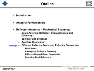
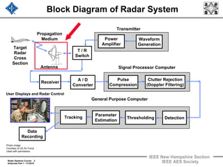
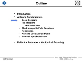
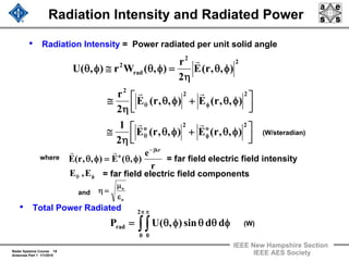
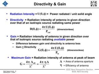
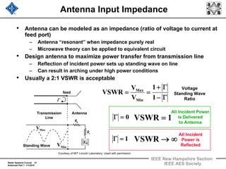
Illumination of Two-Dimensional
Apertures
( )φθ,E
y
x
z
Antenna
Aperture in
plane
•
yx−
φ
θ
( ) ( ) ( ) ( )[ ]
dydxey,xA,E sinycosxsin/j2 φ+φθλπ
∫∫=φθ
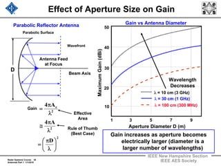
• Calculation of this integral is
non-trivial
– Numerical techniques used
• Field pattern separable,
when aperture illumination
separable
• Problem reduces to two 1
dimensional calculations
( ) ( ) ( )yAxAy,xA yx=
50. Radar Systems Course 50
Antennas Part 1 1/1/2010
IEEE New Hampshire Section
IEEE AES Society
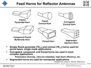
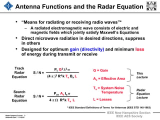
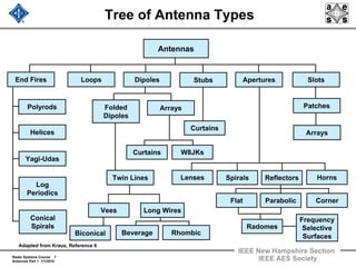
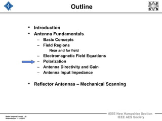
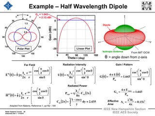
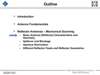
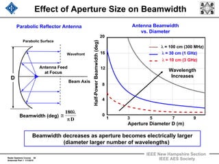
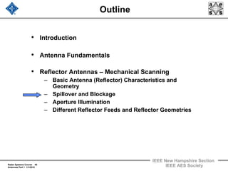
Uniformly Illuminated Circular Aperture
• Use cylindrical coordinates, field intensity independent of
• Half power beamwidth (degrees) = , first sidelobe = - 17.5 dB
• Tapering of the aperture will broaden the beamwidth and lower the
sidelobes
• Field Intensity of circular
aperture of radius a:
• For uniform aperture
illumination :
-10 -5 0 5 10
0
-10
-20
-30
RelativeRadiationIntensity(dB)
( ) θλπ=ξ sin/a2
( ) ( ) ( )[ ] drrsin/r2JrA2E 0
a
0
φθλππ=θ ∫
( ) ( )
( )
( )ξ
θλπ=ξ
ξξπ=θ
1
1
2
J
sin/a2
/Ja2E
= 1st order Bessel Function
where and
( )a/5.58 λ
Adapted from Skolnik, Reference 1
52. Radar Systems Course 52
Antennas Part 1 1/1/2010
IEEE New Hampshire Section
IEEE AES Society
Taper Efficiency, Spillover, Blockage, and
Total Loss vs. Feed Pattern Edge Taper
Reflector Design is a Tradeoff of Aperture Illumination (Taper)
Efficiency, Spillover and Feed Blockage
Total Loss
Spillover
Feed Blockage
Taper
Efficiency
-20.0 -17.5 -15.0 -12.5 -10.0 -7.5 -5.0
Feed Pattern Edge Taper (dB)
Loss(dB)
-2.0
-1.5
-1.0
0.0
- 0.5
Adapted from Cooley in Skolnik, Reference 4
53. Radar Systems Course 53
Antennas Part 1 1/1/2010
IEEE New Hampshire Section
IEEE AES Society
Outline
• Introduction
• Antenna Fundamentals
• Reflector Antennas – Mechanical Scanning
– Basic Antenna (Reflector) Characteristics and
Geometry
– Spillover and Blockage
– Aperture Illumination
– Different Reflector Feeds and Reflector Geometries
Feed Horns
Cassegrain Reflector Geometry
Different Shaped Beam Geometries
Scanning Feed Reflectors
54. Radar Systems Course 54
Antennas Part 1 1/1/2010
IEEE New Hampshire Section
IEEE AES Society
Feed Horns for Reflector Antennas
• Simple flared pyramidal (TE01) and conical (TE11) horns used for
pencil beam, single mode applications
• Corrugated, compound, and finned horns are used in more
complex applications
– Polarization diversity, ultra low sidelobes, high beam efficiency, etc.
• Segmented horns are used for monopulse applications
Flared
Pyramidal Horn Corrugated
Conical Horn
Flared
Conical Horn
Segmented
Aperture Horn
Finned Horn
Compound Flared
Multimode Horn
Adapted from Cooley in Skolnik, Reference 4
55. Radar Systems Course 55
Antennas Part 1 1/1/2010
IEEE New Hampshire Section
IEEE AES Society
Cassegrain Reflector Antenna
Ray Trace of
Cassegrain Antenna
Geometry of
Cassegrain Antenna Figure by MIT OCW.
56. Radar Systems Course 56
Antennas Part 1 1/1/2010
IEEE New Hampshire Section
IEEE AES Society
Advantages of Cassegrain Feed
• Lower waveguide loss because feed is not at the focus of the
paraboloid, but near the dish.
• Antenna noise temperature is lower than with conventional
feed at focus of the paraboloid
– Length of waveguide from antenna feed to receiver is shorter
– Sidelobe spillover from feed see colder sky rather than warmer
earth
• Good choice for monopulse tracking
– Complex monopulse microwave plumbing may be placed
behind reflector to avoid the effects of aperture blocking
57. Radar Systems Course 57
Antennas Part 1 1/1/2010
IEEE New Hampshire Section
IEEE AES Society
ALTAIR- Example of Cassegrain Feed
Dual Frequency Radar
ALTAIR Antenna ALTAIR Antenna Feed
• Antenna size - 120 ft.
• VHF parabolic feed
• UHF Cassegrain feed
• Frequency Selective Surface
(FSS) used for reflector at
UHF
• This “saucer” is a dichroic FFS that is
reflective at UHF and transparent at
VHF. The “teacup” to its right is the
cover for a five horn VHF feed,
located at the antenna’s focal point.
• The FSS sub-reflector is composed of
two layers of crossed dipoles
Note size of
man
Courtesy of MIT Lincoln Laboratory, Used with permission
58. Radar Systems Course 58
Antennas Part 1 1/1/2010
IEEE New Hampshire Section
IEEE AES Society
Antennas with Cosecant-Squared
Pattern
• Air surveillance coverage of a simple fan beam is usually
inadequate for aircraft targets at high altitude and short range
– Simple fan beam radiates very little energy at high altitude
• One technique - Use fan beam
with shape proportional to the
square of the cosecant of the
elevation angle
– Gain constant for a given
altitude
• Gain pattern:
– G(θ) = G(θ1) csc2 θ / csc2 θ 1
for θ1< θ < θ 2
– G(θ) ~ G(θ1) (2 - cot θ2)
hh
R
csc2 Beam
hmax.
Parabolic
Fan Beam
θ2
θ1
59. Radar Systems Course 59
Antennas Part 1 1/1/2010
IEEE New Hampshire Section
IEEE AES Society
Antenna Pattern with Cosecant-Squared
Beam Shaping
Parabolic Reflector
Csc2 Shaped Reflector
Parabolic Reflector
Ray Trace for csc2 Antenna Pattern FAA ASR Radars Use
csc2 Antenna Reflector Shaping
ASR-9 Antenna
Courtesy of US Dept of Commerce
60. Radar Systems Course 60
Antennas Part 1 1/1/2010
IEEE New Hampshire Section
IEEE AES Society
Patterns for Offset Feeds
• Notice that a vertical array of feeds results in a set of
“stacked beams”
– Can be used to measure height of target
-10 0 10 20 30 40
Angle (deg)
RelativeGain(dB)
-30
0
-10
-20
θ = 0°
5° 10°
15°
20°
θ
Frequency = 3 GHz
94 in
f = 32 in.
Feed horns
2.5 in. square
61. Radar Systems Course 61
Antennas Part 1 1/1/2010
IEEE New Hampshire Section
IEEE AES Society
Example of Stacked Beam Antenna
• Stacked beam surveillance radars can cost effectively measure
height of target, while simultaneously performing the surveillance
function
• This radar, which was developed in the 1970s, under went a
number of antenna upgrade in the 1990s (TPS-70, TPS-75)
– Antenna was replaced with a slotted waveguide array, which
performs the same functions, and in addition has very low sidelobes
TPS-43 Radar
TPS-43 Antenna Feed
Courtesy of brewbooks
Courtesy of US Air Force
62. Radar Systems Course 62
Antennas Part 1 1/1/2010
IEEE New Hampshire Section
IEEE AES Society
Example of Stacked Beam Antenna
• Stacked beam surveillance radars can cost effectively measure height
of target, while simultaneously performing the surveillance function
• This radar, which was developed in the 1970s, was replaced in the
1990s with a technologically modern version of the radar.
– New antenna, a slotted waveguide array, has all of the same functionality
as TPS-43 dish, but in addition, has very low antenna sidelobes
TPS-43 Radar TPS-78 Antenna
Courtesy of Northrop Grumman
Used with Permission
Courtesy of US Air Force
63. Radar Systems Course 63
Antennas Part 1 1/1/2010
IEEE New Hampshire Section
IEEE AES Society
Scanning Feed Reflector Antennas
• Scanning of the radar beam over a limited angle
with a fixed reflector and a movable feed
– Paraboloid antenna cannot be scanned too far without
deterioration
Gain of antenna, with f/D=.25, reduced to 80%when beam
scanned 3 beamwidths off axis
– Wide angle scans in one dimension can be obtained
with a parabolic torus configuration
Beam is generated by moving feed along circle whose radius is
1/2 that of torus circle
Scan angle limited to about 120 deg
Economical way to rapidly scan beam of very large antennas over
wide scan angles
– Organ pipe scanner
Mechanically scan feed between many fixed feeds
64. Radar Systems Course 64
Antennas Part 1 1/1/2010
IEEE New Hampshire Section
IEEE AES Society
Examples of Scanning Feed Reflector
Configuration
Parabolic Torus Antenna
R
R
f
f
= Radius of Torus
= Focal Length of Torus
The output feed horns of the organ pipe
scanner are located along this arc
Organ Pipe Scanner Feed
The length of each
waveguide is equal
Outputs
to
Antenna
Horn
From Transmitter
65. Radar Systems Course 65
Antennas Part 1 1/1/2010
IEEE New Hampshire Section
IEEE AES Society
Radar Example – Organ Pipe Scanner
Courtesy of MIT Lincoln Laboratory, Used with permission
66. Radar Systems Course 66
Antennas Part 1 1/1/2010
IEEE New Hampshire Section
IEEE AES Society
Radar Example – Organ Pipe Scanner
BMEWS Site, Clear, Alaska
Courtesy of MIT Lincoln Laboratory, Used with permission
67. Radar Systems Course 67
Antennas Part 1 1/1/2010
IEEE New Hampshire Section
IEEE AES Society
Summary – Part 1
• Discussion of antenna parameters
– Gain
– Sidelobes
– Beamwidth
Variation with antenna aperture size and wavelength
– Polarization
Horizontal, Vertical, Circular
• Mechanical scanning antennas offer an inexpensive method
of achieving radar beam agility
– Slow to moderate angular velocity and acceleration
• Different types of mechanical scanning antennas
– Parabolic reflectors
– Cassegrain and offset feeds
– Stacked beams
• Antenna Issues
– Aperture illumination
– Antenna blockage and beam spillover
68. Radar Systems Course 68
Antennas Part 1 1/1/2010
IEEE New Hampshire Section
IEEE AES Society
Homework Problems
• From Skolnik, Reference 2
– Problem 2.20
– Problems 9.2, 9.4, 9.5, and 9.8
69. Radar Systems Course 69
Antennas Part 1 1/1/2010
IEEE New Hampshire Section
IEEE AES Society
Outline
• Introduction
• Antenna Fundamentals
• Reflector Antennas – Mechanical Scanning
• Phased Array Antennas
• Frequency Scanning of Antennas
• Hybrid Methods of Scanning
• Other Topics
70. Radar Systems Course 70
Antennas Part 1 1/1/2010
IEEE New Hampshire Section
IEEE AES Society
Acknowledgement
• Dr. Pamela Evans
• Dr Alan J. Fenn
71. Radar Systems Course 71
Antennas Part 1 1/1/2010
IEEE New Hampshire Section
IEEE AES Society
References
1. Balanis, C. A., Antenna Theory: Analysis and Design, Wiley,
New York, 3rd Ed., 2005
2. Skolnik, M., Introduction to Radar Systems, McGraw-Hill,
New York, 3rd Ed., 2001
3. Mailloux, R. J., Phased Array Antenna Handbook, Artech
House, Norwood, MA, 1994
4. Skolnik, M., Radar Handbook, McGraw-Hill, New York, 3rd
Ed., 2008
5. Skolnik, M., Radar Handbook, McGraw-Hill, New York, 2nd
Ed., 2008
6. Kraus, J.D. et. al., Antennas, McGraw-Hill, New York, 1993.
7. Ulaby, F. T. , Fundamentals of Applied Electromagnetics, 5th
Ed., Pearson, Upper Saddle River, NJ, 2007