Radar uses radio waves to detect objects and determine their range, altitude, direction or speed. It works by transmitting pulses of radio waves which bounce off objects and return a portion of energy to the receiving antenna. Radar was developed in the 1930s-1940s and has two main types - pulse radar which uses pulse transmission and continuous wave radar which uses continuous transmission. Key components of radar systems include the transmitter, antenna, receiver and display. Factors like signal reception, bandwidth, power and beam width affect radar performance.
Introduction to radar as an object-detection system using radio waves. Definition of RADAR.
Overview of radar history before WWII, highlighting key innovators and developments in radar technology.
Description of radar working principles including transmission and reflection of radio waves, and Doppler effect.
Implications of reflection and dielectric properties on radar detection, including radar material interaction.
Introduction to the radar equation, explaining key parameters and the impact of distance on power reception.
Explanation of how ground-based radar systems utilize the Doppler effect to detect speeds of objects.
Overview of basic types of radar: Pulse Transmission and Continuous Wave radar.
Key factors influencing pulse transmission, including minimum and maximum range, power, and pulse repetition frequency (PRF).
Details on continuous wave radar operation, highlighting Doppler shift and the components involved. Differences between pulse and continuous wave radar, focusing on data acquisition and susceptibility to jamming.
Antenna roles in radar systems including transmitting energy and beam formation, as well as accuracy.
Measuring azimuths and determining altitude based on radar signals.
Methods for concentrating radar energy using beam forming and reflector shapes.
Function of wave guides in radar systems for energy shielding and signal management.
Key performance factors for radar systems including signal reception, bandwidth, and pulse characteristics.
How radar measures distance and speed using transmission time and Doppler effect principles.
Importance of receiver sensitivity on radar performance and detection capabilities.Effects of pulse properties on radar performance including shape, width, and compression.
Summary of trade-offs in radar design including sensitivities, frequencies, and equipment size.
Overview of specific radar types and technologies, highlighting their unique applications in various fields.
Discussion of radar applications in military, aviation, marine navigation, weather monitoring, and geology.
INTRODUCTIONINTRODUCTION
Radar is anobject-detection system that uses electromagnetic waves -
specifically radio waves - to identify the range, altitude, direction or speed of
both moving and fixed objects such as aircraft, ships, spacecraft, mountain
ranges, radio and TV towers, guided missiles, motor vehicles, weather
formations, and terrain. The radar dish, or antenna, transmits pulses of radio
waves or microwaves which bounce off any object in their path. The object
returns a tiny part of the wave's energy to a dish or antenna which is usually
located at the same site as the transmitter.
The term RADAR was coined in 1940 by electronics engineers working for
the U.S. Navy as an acronym for RAdio Detection And Ranging.
3.
BRIEF HISTORYBRIEF HISTORY
Beforethe Second World War developments by the British, the Germans, the
French, the Soviets and the Americans led to the modern version of radar. In
1934 the French Émile Girardeau stated he was building a radar system
"conceived according to the principles stated by Tesla" and obtained a patent
(French Patent n° 788795 in 1934) for a working dual radar system, a part of
which was installed on the Normandie liner in 1935.The same year, American
Dr. Robert M. Page tested the first monopulse radar and the Soviet military
engineer P.K.Oschepkov, in collaboration with Leningrad Electrophysical
Institute, produced an experimental apparatus RAPID capable of detecting an
aircraft within 3 km of a receiver. Hungarian Zoltán Bay produced a working
model by 1936 at the Tungsram laboratory in the same vein.
The British were the first to fully exploit radar as a defence against aircraft
attack. This was spurred on by fears that the Germans were developing death
rays. The Air Ministry asked British scientists in 1934 to investigate the
possibility of propagating electromagnetic energy and the likely effect
4.
BASIC PRINCIPLESBASIC PRINCIPLES
Aradar system has a transmitter that emits radio waves called radar signals in
predetermined directions. When these come into contact with an object they are
usually reflected and/or scattered in many directions. Radar signals are reflected
especially well by materials of considerable electrical conductivity - especially
by most metals, by seawater, by wet land, and by wetlands. Some of these make
the use of radar altimeters possible. The radar signals that are reflected back
towards the transmitter are the desirable ones that make radar work. If the
object is moving either closer or farther away, there is a slight change in the
frequency of the radio waves, due to the Doppler effect.
Radar receivers are usually, but not always, in the same location as the
transmitter. Although the reflected radar signals captured by the receiving
antenna are usually very weak, these signals can be strengthened by the
electronic amplifiers that all radar sets contain. More sophisticated methods of
signal processing are also nearly always used in order to recover useful radar
signals.
5.
The weak absorptionof radio waves by the medium through which it passes is
what enables radar sets to detect objects at relatively-long ranges - ranges at
which other electromagnetic wavelengths, such as visible light, infrared light,
and ultraviolet light, are too strongly attenuated. In particular, there are
weather conditions under which radar works well regardless of the weather.
Such things as fog, clouds, rain, falling snow, and sleet that block visible light
are usually transparent to radio waves. Certain, specific radio frequencies that
are absorbed or scattered by water vapor, raindrops, or atmospheric gases
(especially oxygen) are avoided in designing radars except when detection of
these is intended.
Finally, radar relies on its own transmissions, rather than light from the Sun or
the Moon, or from electromagnetic waves emitted by the objects themselves,
such as infrared wavelengths (heat). This process of directing artificial radio
waves towards objects is called illumination, regardless of the fact that radio
waves are completely invisible to the human eye or cameras.
6.
Reflection
Brightness can indicatereflectivity as in this 1960 weather radar image (of Hurricane Abby). The
radar's frequency, pulse form, polarization, signal processing, and antenna determine what it can
observe.
Electromagnetic waves reflect (scatter) from any large change in the dielectric constant or
diamagnetic constants. This means that a solid object in air or a vacuum, or other significant change
in atomic density between the object and what is surrounding it, will usually scatter radar (radio)
waves. This is particularly true for electrically conductive materials, such as metal and carbon fiber,
making radar particularly well suited to the detection of aircraft and ships. Radar absorbing
material, containing resistive and sometimes magnetic substances, is used on military vehicles to
reduce radar reflection. This is the radio equivalent of painting something a dark color so that it
cannot be seen through normal means (see stealth technology).
Radar waves scatter in a variety of ways depending on the size (wavelength) of the radio wave and
the shape of the target. If the wavelength is much shorter than the target's size, the wave will
bounce off in a way similar to the way light is reflected by a mirror. If the wavelength is much
longer than the size of the target, the target may not be visible due to poor reflection. Low
Frequency radar technology is dependent on resonances for detection, but not identification of
targets. This is described by Rayleigh scattering, an effect that creates the Earth's blue sky and red
sunsets. When the two length scales are comparable, there may be resonances. Early radars used
very long wavelengths that were larger than the targets and received a vague signal, whereas some
modern systems use shorter wavelengths (a few centimeters or shorter) that can image objects as
small as a loaf of bread.
7.
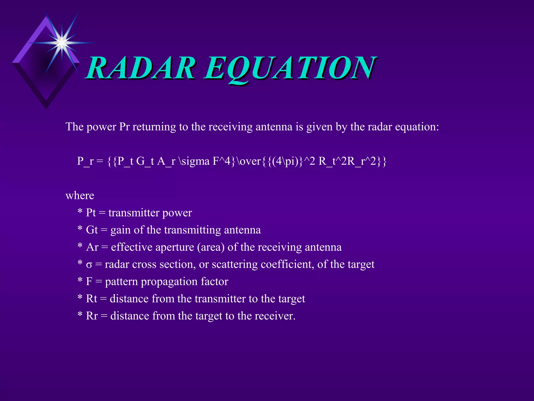
RADAR EQUATIONRADAR EQUATION
Thepower Pr returning to the receiving antenna is given by the radar equation:
P_r = {{P_t G_t A_r sigma F^4}over{{(4pi)}^2 R_t^2R_r^2}}
where
* Pt = transmitter power
* Gt = gain of the transmitting antenna
* Ar = effective aperture (area) of the receiving antenna
* σ = radar cross section, or scattering coefficient, of the target
* F = pattern propagation factor
* Rt = distance from the transmitter to the target
* Rr = distance from the target to the receiver.
8.
In the commoncase where the transmitter and the receiver are at the same
location, Rt = Rr and the term Rt² Rr² can be replaced by R4, where R is the
range. This yields:
This shows that the received power declines as the fourth power of the range,
which means that the reflected power from distant targets is very, very small.
The equation above with F = 1 is a simplification for vacuum without
interference. The propagation factor accounts for the effects of multipath and
shadowing and depends on the details of the environment. In a real-world
situation, pathloss effects should also be considered.
9.
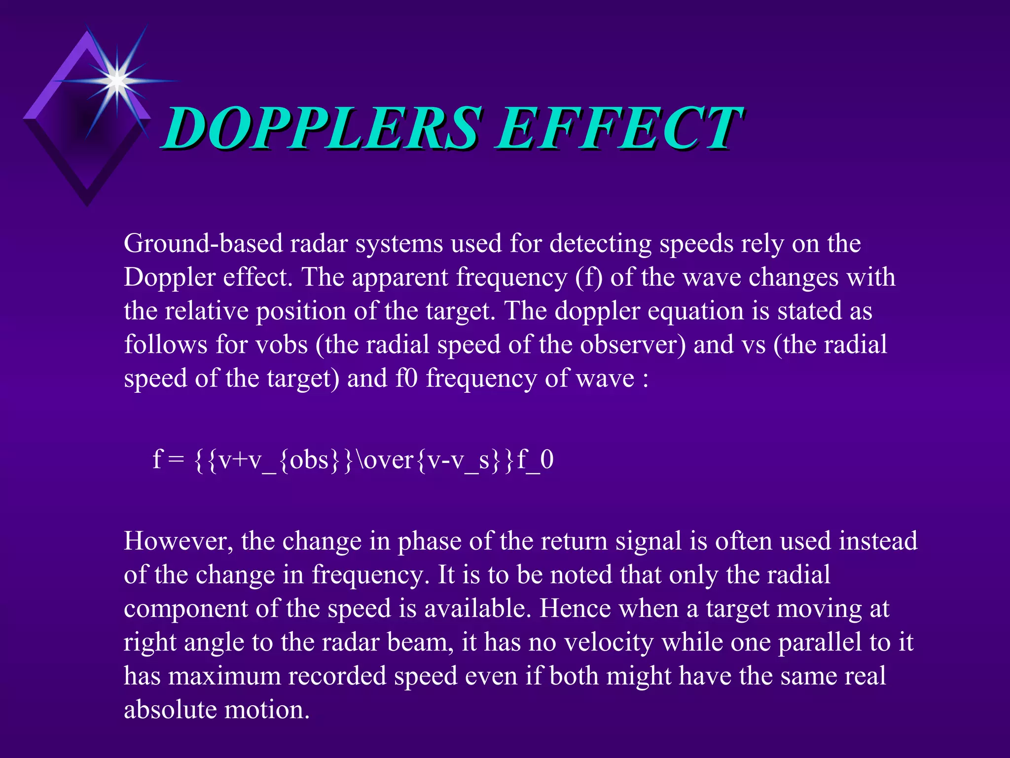
DOPPLERS EFFECTDOPPLERS EFFECT
Ground-basedradar systems used for detecting speeds rely on the
Doppler effect. The apparent frequency (f) of the wave changes with
the relative position of the target. The doppler equation is stated as
follows for vobs (the radial speed of the observer) and vs (the radial
speed of the target) and f0 frequency of wave :
f = {{v+v_{obs}}over{v-v_s}}f_0
However, the change in phase of the return signal is often used instead
of the change in frequency. It is to be noted that only the radial
component of the speed is available. Hence when a target moving at
right angle to the radar beam, it has no velocity while one parallel to it
has maximum recorded speed even if both might have the same real
absolute motion.
Range vs. Power/PW/PRFRangevs. Power/PW/PRF
•Minimum Range: If still transmitting when return
received RETURN NOT SEEN.
•Max Range: PRFPWPRT
PW
PeakPower
erAveragePow
*==
As min Rh max Rh
PW
PRF
14.
2. Pulse repetitionfrequency (PRF)
a. Pulses per second
b. Relation to pulse repetition time (PRT)
c. Effects of varying PRF
(1) Maximum range
(2) Accuracy
3. Peak power
a. Maximum signal power of any pulse
b. Affects maximum range of radar
15.
4. Average power
a.Total power transmitted per unit of time
b. Relationship of average power to PW and PRT
5. Duty cycle
a. Ratio PW (time transmitting) to PRT (time of entire cycle,
time transmitting plus rest time)
b. Also equal to ratio of average power to peak power
16.
Determining Range WithPulse RadarDetermining Range With Pulse Radar
2
*tc
Range =
c = 3 x 10⁸
m/sec
t is time to receive return
divide by 2 because pulse traveled to object and back
17.
Pulse TransmissionPulse Transmission
PulseWidth (PW)Pulse Width (PW)
Length or duration of a given pulse
Pulse Repetition Time (PRT=1/PRF)Pulse Repetition Time (PRT=1/PRF)
PRT is time from beginning of one pulse to the
beginning of the next
PRF is frequency at which consecutive pulses are
transmitted.
PW can determine the radar’s minimum detectionPW can determine the radar’s minimum detection
range; PW can determine the radar’s maximumrange; PW can determine the radar’s maximum
detection range.detection range.
PRF can determine the radar’s maximum detectionPRF can determine the radar’s maximum detection
range.range.
18.
D.D. Describe thecomponents of a pulse radarDescribe the components of a pulse radar
system.system.
1. Synchronizer
2. Transmitter
3. Antenna
4. Duplexer
5. Receiver
6. Display unit
7. Power supply
19.
Pulse Radar BlockDiagramPulse Radar Block Diagram
Power
Supply
Synchronizer
Transmitter
Display
Duplexer
(Switching Unit)
Receiver
Antenna
Antenna Bearing or Elevation
Video
Echo
ATRRF
TR
20.
Continuous Wave RadarContinuousWave Radar
Employs continualEmploys continual
RADAR transmissionRADAR transmission
Separate transmit andSeparate transmit and
receive antennasreceive antennas
Relies on theRelies on the
“DOPPLER SHIFT”“DOPPLER SHIFT”
21.
Doppler Frequency ShiftsDopplerFrequency Shifts
Motion Away:
Echo Frequency Decreases
Motion Towards:
Echo Frequency Increases
Pulse Vs. ContinuousWavePulse Vs. Continuous Wave
Pulse EchoPulse Echo
Single AntennaSingle Antenna
Gives Range, usuallyGives Range, usually
Alt. as wellAlt. as well
Susceptible ToSusceptible To
JammingJamming
Physical RangePhysical Range
Determined By PWDetermined By PW
and PRF.and PRF.
Continuous WaveContinuous Wave
Requires 2 AntennaeRequires 2 Antennae
Range or Alt. InfoRange or Alt. Info
High SNRHigh SNR
More Difficult to JamMore Difficult to Jam
But Easily DeceivedBut Easily Deceived
Amp can be tuned toAmp can be tuned to
look for expectedlook for expected
frequenciesfrequencies
24.
RADAR Wave ModulationRADARWave Modulation
Amplitude Modulation
– Vary the amplitude of the carrier sine wave
Frequency Modulation
– Vary the frequency of the carrier sine wave
Pulse-Amplitude Modulation
– Vary the amplitude of the pulses
Pulse-Frequency Modulation
– Vary the Frequency at which the pulses occur
AntennaeAntennae
Two Basic Purposes:TwoBasic Purposes:
Radiates RF Energy
Provides Beam Forming and Focus
Must Be 1/2 of the Wave Length for theMust Be 1/2 of the Wave Length for the
maximum wave length employedmaximum wave length employed
Wide Beam pattern for Search, NarrowWide Beam pattern for Search, Narrow
for Trackfor Track
Concentrating Radar EnergyConcentratingRadar Energy
Through Beam FormationThrough Beam Formation
Linear ArraysLinear Arrays
Uses the Principle of wave summation (constructive
interference) in a special direction and wave
cancellation (destructive interference) in other
directions.
Made up of two or more simple half-wave antennas.
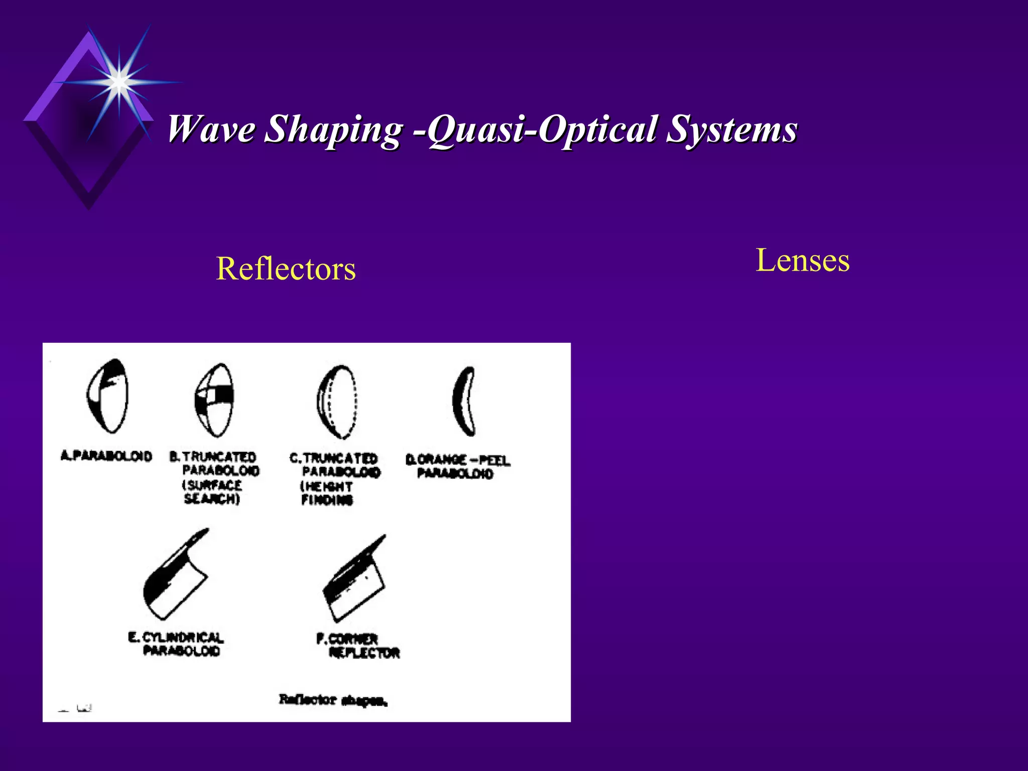
Quasi-opticalQuasi-optical
Uses reflectors and “lenses” to shape the beam.
31.
Reflector ShapeReflector Shape
Paraboloid- Conical Scan used for fireParaboloid - Conical Scan used for fire
control - can be CW or Pulsecontrol - can be CW or Pulse
Orange Peel Paraboliod - Usually CWOrange Peel Paraboliod - Usually CW
and primarily for fire controland primarily for fire control
Parabolic Cylinder - Wide search beam -Parabolic Cylinder - Wide search beam -
generally larger and used for long-rangegenerally larger and used for long-range
search applications - Pulsesearch applications - Pulse
Wave GuidesWave Guides
Usedas a medium forUsed as a medium for
high energy shielding.high energy shielding.
Uses A Magnetic Field toUses A Magnetic Field to
keep the energy centeredkeep the energy centered
in the wave guide.in the wave guide.
Filled with an inert gasFilled with an inert gas
to prevent arcing due toto prevent arcing due to
high voltages within thehigh voltages within the
waveguide.waveguide.
Factors That AffectRadarFactors That Affect Radar
PerformancePerformance
Signal ReceptionSignal Reception
Receiver BandwidthReceiver Bandwidth
Pulse ShapePulse Shape
Power RelationPower Relation
Beam WidthBeam Width
Pulse RepetitionPulse Repetition
FrequencyFrequency
Antenna GainAntenna Gain
Radar Cross Section ofRadar Cross Section of
TargetTarget
Signal-to-noise ratioSignal-to-noise ratio
Receiver SensitivityReceiver Sensitivity
Pulse CompressionPulse Compression
Scan RateScan Rate
Mechanical
Electronic
Carrier FrequencyCarrier Frequency
Antenna apertureAntenna aperture
36.
Radar Receiver PerformanceRadarReceiver Performance
FactorsFactors
Signal ReceptionSignal Reception
Signal-to-Noise RatioSignal-to-Noise Ratio
Receiver BandwidthReceiver Bandwidth
Receiver SensitivityReceiver Sensitivity
37.
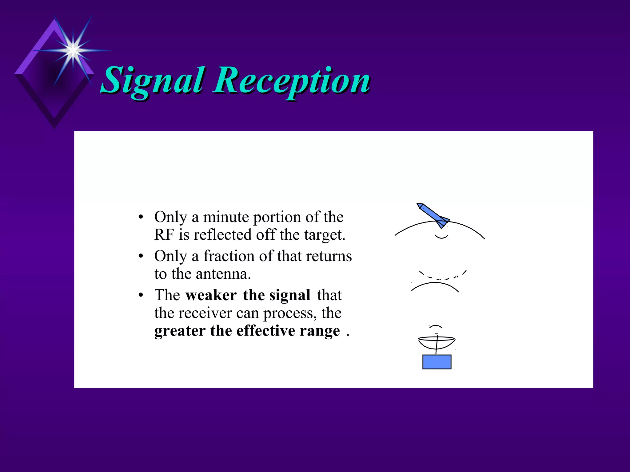
Signal ReceptionSignal Reception
•Only a minute portion of the
RF is reflected off the target.
• Only a fraction of that returns
to the antenna.
• The weaker the signal that
the receiver can process, the
greater the effective range .
38.
Signal-to-Noise RatioSignal-to-Noise Ratio
Measuredin dB!!!!!Measured in dB!!!!!
Ability to recognize target in random noise.Ability to recognize target in random noise.
Noise is always present.
At some range, noise is greater that target’s return.
Noise sets the absolute lower limit of the unit’sNoise sets the absolute lower limit of the unit’s
sensitivity.sensitivity.
Threshold levelThreshold level used to remove excess noise.used to remove excess noise.
39.
Receiver BandwidthReceiver Bandwidth
Isthe frequency range the receiver can process.Is the frequency range the receiver can process.
Receiver must process many frequenciesReceiver must process many frequencies
Pulse are generated by summation of sine waves of
various frequencies.
Frequency shifts occur from Doppler Effects.
Reducing the bandwidthReducing the bandwidth
Increases the signal-to-noise ratio(good)
Distorts the transmitted pulse(bad)
40.
RADAR SIGNAL PROCESSING
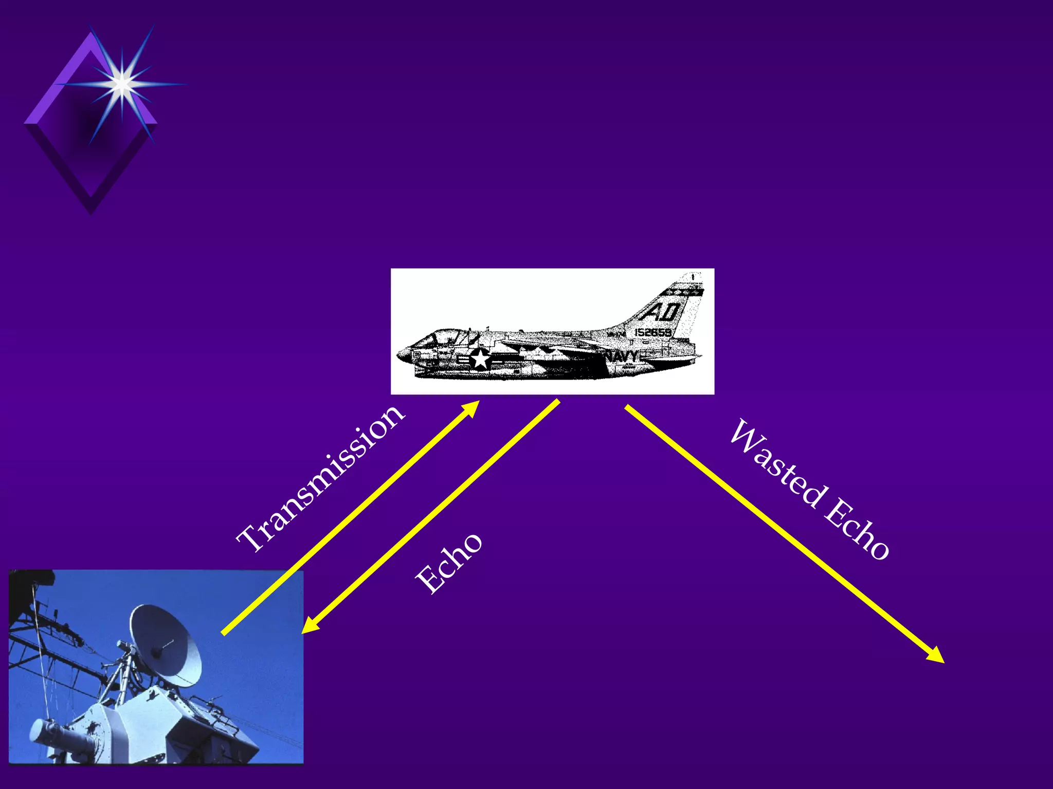
Distancemeasurement
Transit time
Pulse radar
Sonar radar
One way to measure the distance to an object is to transmit a short pulse of radio signal
(electromagnetic radiation), and measure the time it takes for the reflection to return. The
distance is one-half the product of the round trip time (because the signal has to travel to
the target and then back to the receiver) and the speed of the signal. Since radio waves
travel at the speed of light (186,000 miles per second or 300,000,000 meters per second),
accurate distance measurement requires high-performance electronics.
In most cases, the receiver does not detect the return while the signal is being
transmitted. Through the use of a device called a duplexer, the radar switches between
transmitting and receiving at a predetermined rate. The minimum range is calculated by
measuring the length of the pulse multiplied by the speed of light, divided by two. In
order to detect closer targets one must use a shorter pulse length.
41.
A similar effectimposes a maximum range as well. If the return from the target
comes in when the next pulse is being sent out, once again the receiver cannot tell
the difference. In order to maximize range, longer times between pulses should be
used, referred to as a pulse repetition time (PRT), or its reciprocal, pulse repetition
frequency (PRF).
These two effects tend to be at odds with each other, and it is not easy to combine
both good short range and good long range in a single radar. This is because the
short pulses needed for a good minimum range broadcast have less total energy,
making the returns much smaller and the target harder to detect. This could be
offset by using more pulses, but this would shorten the maximum range again. So
each radar uses a particular type of signal. Long-range radars tend to use long
pulses with long delays between them, and short range radars use smaller pulses
with less time between them. This pattern of pulses and pauses is known as the
pulse repetition frequency (or PRF), and is one of the main ways to characterize a
radar. As electronics have improved many radars now can change their PRF
thereby changing their range. The newest radars fire 2 pulses during one cell, one
for short range 10 km / 6 miles and a separate signal for longer ranges 100 km /60
miles.
43.
SPEED MEASUREMENT
Speed isthe change in distance to an object with respect to time. Thus the existing system for
measuring distance, combined with a memory capacity to see where the target last was, is enough to
measure speed. At one time the memory consisted of a user making grease-pencil marks on the radar
screen, and then calculating the speed using a slide rule. Modern radar systems perform the
equivalent operation faster and more accurately using computers.
However, if the transmitter's output is coherent (phase synchronized), there is another effect that can
be used to make almost instant speed measurements (no memory is required), known as the Doppler
effect. Most modern radar systems use this principle in the pulse-doppler radar system. Return
signals from targets are shifted away from this base frequency via the Doppler effect enabling the
calculation of the speed of the object relative to the radar. The Doppler effect is only able to
determine the relative speed of the target along the line of sight from the radar to the target. Any
component of target velocity perpendicular to the line of sight cannot be determined by using the
Doppler effect alone, but it can be determined by tracking the target's azimuth over time.
44.
Receiver SensitivityReceiver Sensitivity
Smallestreturn signal that is discernibleSmallest return signal that is discernible
against the noise background.against the noise background.
Milliwatts range.
An important factor in determining theAn important factor in determining the
unit’s maximum range.unit’s maximum range.
45.
Pulse Effects onRadarPulse Effects on Radar
PerformancePerformance
Pulse ShapePulse Shape
Pulse WidthPulse Width
Pulse CompressionPulse Compression
Pulse PowerPulse Power
46.
Pulse ShapePulse Shape
Determinesrange accuracy andDetermines range accuracy and
minimum and maximum range.minimum and maximum range.
Ideally we want a pulse with verticalIdeally we want a pulse with vertical
leading and trailing edges.leading and trailing edges.
Very clear signal – easily discerned when
listening for the echo.
47.
Pulse WidthPulse Width
Determinesthe range resolution.Determines the range resolution.
Determines the minimum detectionDetermines the minimum detection
range.range.
Can also determine the maximum rangeCan also determine the maximum range
of radar.of radar.
The narrower the pulse, the better theThe narrower the pulse, the better the
range resolution.range resolution.
48.
Pulse CompressionPulse Compression
Increasesfrequency of the wave withinIncreases frequency of the wave within
the pulse.the pulse.
Allows for good range resolution whileAllows for good range resolution while
packing enough power to provide a largepacking enough power to provide a large
maximum range.maximum range.
49.
Pulse PowerPulse Power
The“Ummph” to get the signal out aThe “Ummph” to get the signal out a
long way.long way.
High peak power is desirable to achieveHigh peak power is desirable to achieve
maximum ranges.maximum ranges.
Low power means smaller and moreLow power means smaller and more
compact radar units and less powercompact radar units and less power
required to operate.required to operate.
50.
Other Factors AffectingPerformanceOther Factors Affecting Performance
Scan Rate and Beam WidthScan Rate and Beam Width
Narrow beam require slower antenna rotation rate.
Pulse Repetition FrequencyPulse Repetition Frequency
Determines radars maximum range(tactical factor).
Carrier FrequencyCarrier Frequency
Determines antenna size, beam directivity and target size.
Radar Cross SectionRadar Cross Section (What the radar can see(reflect))(What the radar can see(reflect))
Function of target size, shape, material, angle and carrier
frequency.
53.
Summary of Factorsand CompromisesSummary of Factors and Compromises
Summary of Factors and Compromises
Pulse Shape Sharp a rise as possible Better range accuracy Require infinite bandwidth, more complex
Tall as possible More power /longer range Requires larger equipment/more power
Pulse Width Short as possible Closer minimum range Reduces maximum range
More accurate range
Pulse Repetition Freq. Short Better range accuracy Reduces maximum range
Better angular resolution
Better detection probability
Pulse Compression Uses technique Greater range More complex circuitry
Shorter minimum range
Power More Greater maximum range Requires larger equipment & power
Beam Width Narrow Greater angular accuracy Slow antenna rate, Detection time
Carrier Frequency High Greater target resolution Reduces maximum range
Detects smaller targets
Smaller equipment
Receiver Sensitivity High Maximizes detection range More complex equipment
Receiver Bandwidth Narrow Better signal-to-noise ratio Distorts pulse shape
Factor Desired Why Trade-off Required
54.
Specific Types ofRadarSpecific Types of Radar
Frequency Modulated CW RadarFrequency Modulated CW Radar
Use for radar altimeters and missile guidance.
Pulse DopplerPulse Doppler
Carrier wave frequency within pulse is compared with a reference
signal to detect moving targets.
Moving Target Indicator (MTI) SystemMoving Target Indicator (MTI) System
Signals compared with previous return to enhance moving targets.
(search radars)
Frequency Agile SystemsFrequency Agile Systems
Difficult to jam.
55.
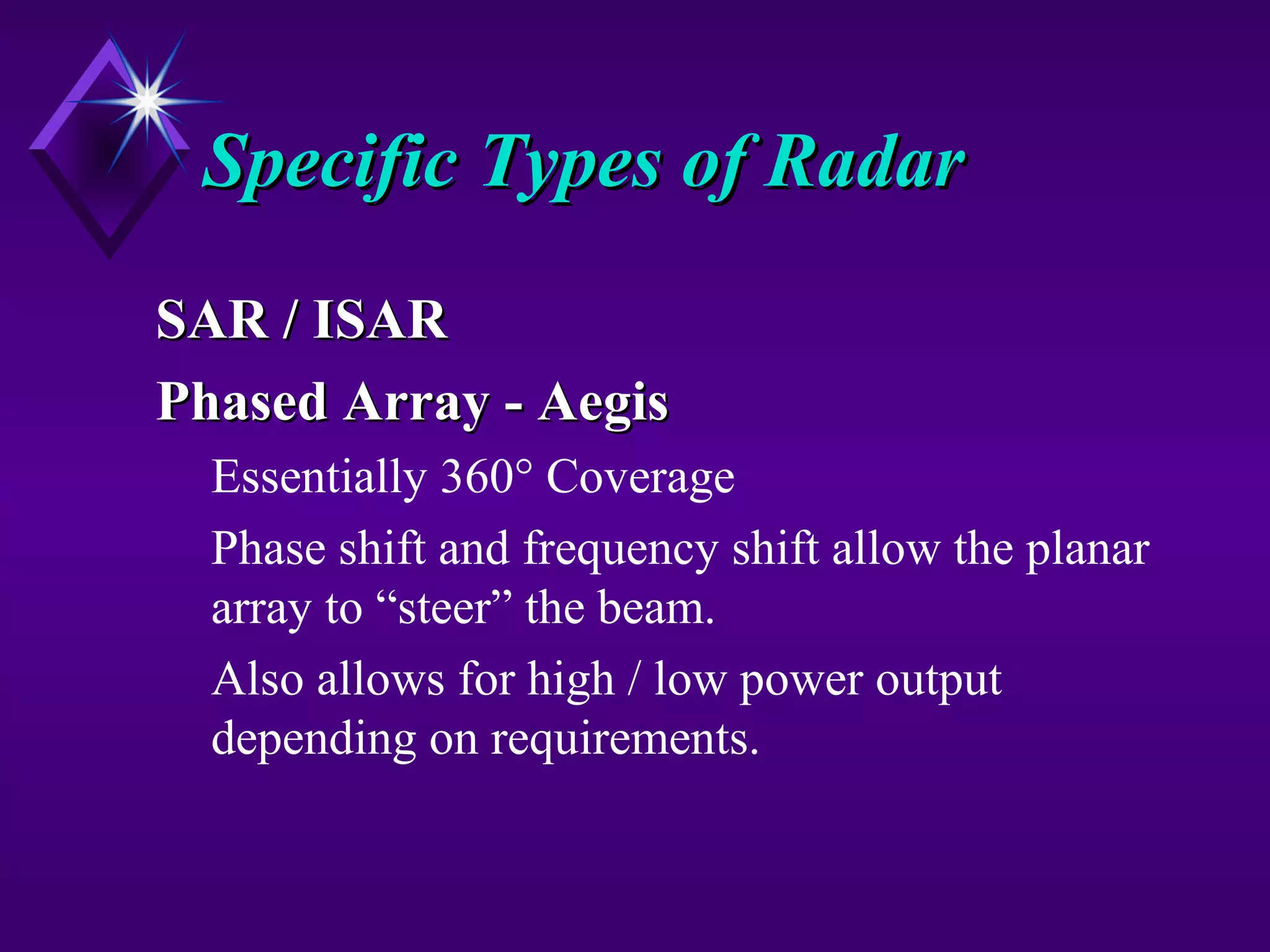
Specific Types ofRadarSpecific Types of Radar
SAR / ISARSAR / ISAR
Phased Array - AegisPhased Array - Aegis
Essentially 360° Coverage
Phase shift and frequency shift allow the planar
array to “steer” the beam.
Also allows for high / low power output
depending on requirements.
APPLICATIONAPPLICATIONThe information providedby radar includes the bearing and range (and therefore position) of the
object from the radar scanner. It is thus used in many different fields where the need for such
positioning is crucial. The first use of radar was for military purposes: to locate air, ground and sea
targets. This evolved in the civilian field into applications for aircraft, ships and roads.
In aviation, aircraft are equipped with radar devices that warn of obstacles in or approaching their
path and give accurate altitude readings. They can land in fog at airports equipped with radar-
assisted ground-controlled approach (GCA) systems, in which the plane's flight is observed on
radar screens while operators radio landing directions to the pilot.
Marine radars are used to measure the bearing and distance of ships to prevent collision with other
ships, to navigate and to fix their position at sea when within range of shore or other fixed
references such as islands, buoys, and lightships. In port or in harbour, vessel traffic service radar
systems are used to monitor and regulate ship movements in busy waters. Police forces use radar
guns to monitor vehicle speeds on the roads.
Radar has invaded many other fields. Meteorologists use radar to monitor precipitation. It has
become the primary tool for short-term weather forecasting and to watch for severe weather such
as thunderstorms, tornadoes, winter storms, precipitation types, etc. Geologists use specialised
ground-penetrating radars to map the composition of the Earth's crust.
Editor's Notes
#2 What is RADAR an acronym for? Radio Detection and Ranging.
Radio wave is generated, transmitted, reflected, and detected.
RADAR unimpaired by night, fog, clouds, smoke.
Not as detailed as actual sight.
RADAR is good for isolated targets against a relatively featureless background.
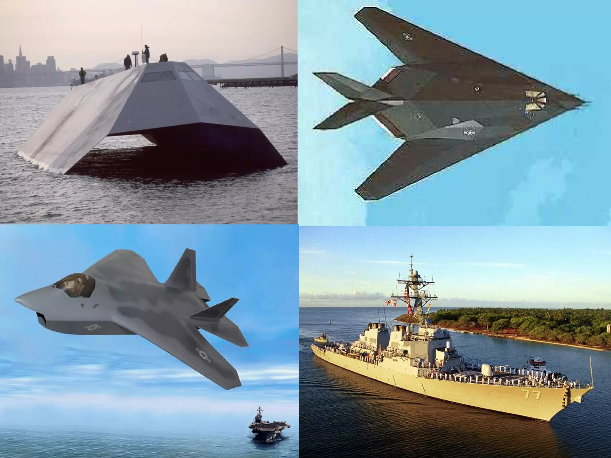
#11 Stealth Ship
Designed to test the effects of stealth technology on Naval Warships.
What kind of radar reflection will we get off this target?
Note the angles, also coated with radar absorbing material.
#12 Pulse - RADAR transmits a series of pulses separated by non-transmission intervals during which the radar “listens” for a return.
Continuous Wave - Constantly emitting radar. Relative motion of either the radar or the target is required to indicate target position. Frequency shift.
#18 1. The pulse width determines the minimum range that the target can be detected.
a. If transmitter is still on when the pulse (echo)is returned then won’t see
the return.
b. Need short pulses to detect close targets.
2. Need long pulses to have sufficient power to reach targets that have long ranges.
3. Pulse Repetition Time, Frequency or Rate.
a. The length of time the transmitter is off (longer PRF) the longer the
radar’s maximum range will be. (Use the drawing to explain)
KEY Points:
1. Varying the pulse width affects the range of the radar.
2. Need short pulses for short range targets.
3. PW determines radar’s minimum range resolution.
4. The slower the PRF the greater the radar’s maximum
range.
5. The faster the PRF the greater the radar’s accuracy.
#21 Second major type of radar.
Produces a constant stream of energy.
Can’t distinguish distances (range) because no interval between pulses.
Can distinguish between moving and non-moving targets by using Doppler frequency shifts.
#22 (p. 104 in text)
1. Doppler frequency shift describes the effect that motion has on a reflected
frequency.
2. Use the diagram to show:
a. If the wall is moving away a ball will have to travel farther than the
previous ball so the reflected balls are further apart.
b. If the wall is moving toward, a ball will have to travel a shorter distance
than the previous ball so the reflected balls are closer together.
3. If you assume that each ball represents the top of a wave so the distance
between each ball represents a wave cycle then you find:
a. The frequency of the echo is lower if the target is moving away.
b. The frequency of the echo is higher if the target is coming towards.
** This is why the sound of a passing train or airplane goes from
higher pitch to lower pitch.
4. Key Points:
a. Frequency expansion is the lowering of the echo frequency caused
by an opening target (target moving away). DOWN DOPPLER
b. Frequency compression is the raising of the echo frequency caused
by the closing target (target moving closer). UP DOPPLER
c. The moving of the transmitter can also cause frequency shifts (it’s
relative motion that produces the effect).
d. The faster the relative motion change the greater the frequency shift.
#23 Make copies for distribution.
1. Transmit/Receive Antennas. Since must operate simultaneously, must be located separately so receiving antenna doesn’t pick up transmitted signal.
2. Oscillator or Power Amplifier. Sends out signal to transmit antenna. Also sends sample signal to Mixer. (used as a reference)
3. Mixer.
a. A weak sample of the transmitted RF energy is combined with the received echo signal.
b. The two signal will differ because of the Doppler shift.
c. The output of the mixer is a function of the difference in frequencies.
4. Amplifier. Increases strength of signal before sending it to the indicator.
5. Discriminator.
a. Selects desired frequency bands for Doppler shifts, eliminates
impossible signals.
b. The unit will only allow certain frequency bands so won’t process stray
signals.
6. Indicator. Displays data. Displays velocity or the component directly inbound or directly outbound. Range is not measured.
7. Filters. Used to reduce noise, used in amp to reduce sea return, land clutter, and other non-desirable targets.
#24 Discuss Slide
Range for CW: (p. 106) Frequency Modulated Continuous Wave.
Altitude for CW: Slant range (see coming slide)
#25 Draw waves on the board and discuss.
1. The basic radar and communication transmission waves are modified to:
a. Allow the system to get more information out of a single transmission.
b. Enhance the signal processing in the receiver.
c. To deal with countermeasures (jamming, etc.)
d. Security (change characteristics)
2. Both CW and Pulse signals can be changed or MODULATED
3. Show slide.
4. Common Modifications are:
a. AM
b. FM
c. Pulse Amplitude
d. Pulse Frequency
5. Modulation is achieved by adding signals together.
#27 The antenna is used to radiate the RF energy created by the transmitter. It also receives the reflected energy and sends it to the receiver. Show slide:
1. Remember from discussion on how a RF transmission is made.
a. A dipole antenna is the simplest form of RF antenna.
b. Optimal radiation is achieved with an antenna length of 1/2
a wave length long or multiples thereof.
c. Electrical field strength is strongest in middle and least at top/bottom.
d. Maximum field strength is perpendicular to the antenna
e. Field extends 360 degrees around antenna.
2. Beam Pattern represents the electromagnetic field around antenna.
a. It is a snap shot at any given time.
b. Lines represents field strength (in the example it is strongest on x axis)
c. Field goes to near zero 30-40 degrees off horizontal axis
3. Simple antenna doesn’t help us locate a target just that he is in the cone.
It would be a help if we could:
a. Illuminate a specific area (for accurate location data)
b. Not wasting power by looking in unwanted directions
c. Focus more power in the area we want to look at
4. We improve system performance and efficiency through manipulation of the beam’s formation. The major way we do this is by the antenna.
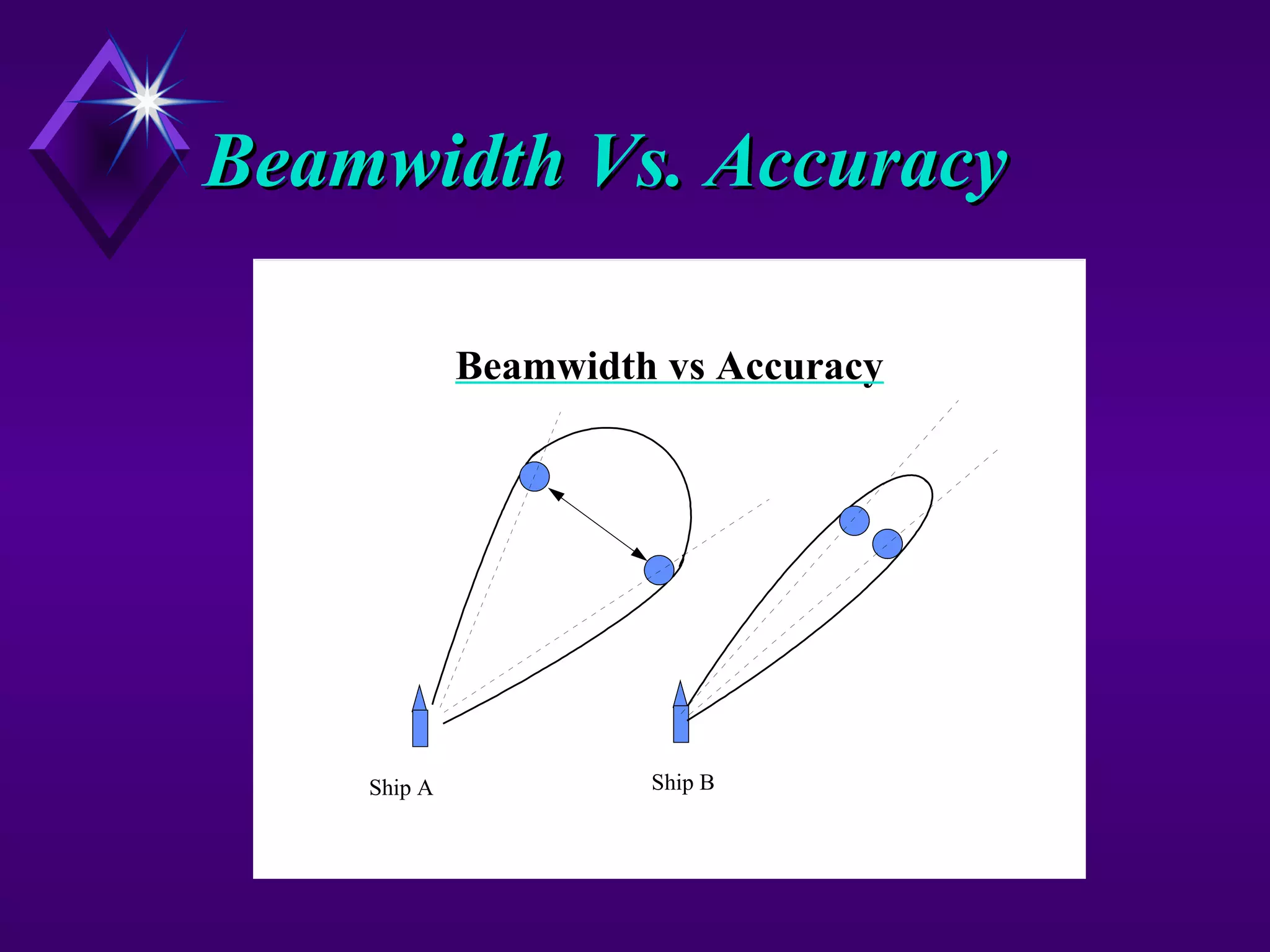
#28 1. The size of the width of the beam (beam-width) determines the angular accuracy of the radar. From drawing we see that the target could be any where in the beam to produce a return. Ship B can more accurately determine where the target really is.
2. The function of the radar determines how narrow the beam-width is needed.
a Search radars sacrifice accuracy for range. (wide beam-widths at high
power)
b. Tracking or targeting radars require more accuracy (narrow beam-
widths)
3. If the target is located on the center line of the beam lobe, the return will be the strongest.
Key Point:. Beam-widths determine the angular accuracy of the radar.
Lead in: Angular accuracy can be use to measure azimuth and elevation depending on which way the antenna is oriented.
#29 1. We get range from measuring the time the pulse takes to get from the antenna until the echo is received back.
2. We can get angular range by measuring the antenna angle from the heading of the ship when it is pointing at the target.
a. Relative heading is just this angle from the ship.
b. For true direction this angle is added to the heading of the ship.
(If the summation is >360 degrees subtract 360 degrees.
#30 1. Show slide to show that angular measurements is simple geometry to determine height.
Note:
a. Must adjust for the height of the radar antenna.
b. If the target is low and point the beam low you could get returns from
the water surface.
- Sea Return or “Sea Clutter”
#31 1.. We have seen the advantages of having a strong, narrow beam.
How do we produce the beam?
2. Show Slide.
3. Linear Arrays:
a. Work because can add waves together to get constructive or destructive
interference.
b. Common types of Linear arrays include: Broadside and Endfire
Arrays.
c. Can employ Parasitic Elements direct the beam.
d. SPY is a phased array radar, more than 4,000 beam for const/dest
4. Lenses:
a. Are like optical lenses they focus the beam through refraction of the
energy wave.
b. Can only effectively be used with very high frequencies such as
microwaves.
c. When you hear of a microwave horn... that is the “lens.”
#35 1. One of the most common Quasi-Optical Systems used to enhance the beams are reflectors.
a. Reflectors are just like the reflectors used in flashlights.
b. They make use of the reflectivity of Electromagnetic waves.
c. Take a simple half-wave dipole antenna and reflect the energy into
one large beam.
2. Because the reflecting surface is not exact and there is some scattering, will get some smaller beams in addition to the major beam. These are called MINOR LOBES. The large beam is the MAJOR LOBE.
#37 Most efficient means of conducting energy from transmitter to the antenna.
A cable would act as a short circuit if use at that high of frequency.
Hollow dialectic gas filled tube of specific dimensions.
Doesn’t work like a wire conducting current. A totally different concept.
Can end in flared tube which transmits the energy
Should know what a wave guide is for and that if dented, crushed or punctured, it can adversely effect the performance of the system.
Don’t bang on wave guides!!
#39 Go through this slide.
See following slides for definitions of the various factors.
Signal Reception:
a. Only a minute portion of the RF is reflected off the target.
b. Only a fraction of that returns to the antenna.
c. The weaker the signal that the receiver can process, the greater the effective range.
Signal-to-Noise Ratio:
a. Noise(always present) sets the absolute lower limit of the sensitivity of the radar sets. (At some range the noise will be greater than the echo)
b. Noise includes atmospheric disturbances, jamming, stray signal. Noise is inherent in the electronic circuits as random electron motion through a resister causes stray noise.
c. To cope with this problem, the operator can set a threshold level. If signals are below this threshold level, they will not be displayed.
If threshold level is set too low, you get many false detections.
If set too high, could mask out real contact, (therefore, operator must compromise the gain).
#40 These are all factors of the design of the radar receiver.
#41 1. Explain why only portion of the signal gets to the target and only a fraction of that signal gets back to the receiver.
#42 Signal-to-Noise Ratio:
a. Noise (always present) sets the absolute lower limit of the sensitivity of
the radar sets. (At some range the noise will be greater than the echo)
Example: Look at a cb radio. If you turn down the volume eventual you will not hear the music only the static. The static is noise.
b. Noise includes atmospheric disturbances, Jamming, stray signals.
Noise is inherent in electronic circuits as random electron
motion through a resister causes stray noise.
c. To cope with this problem, the operator can set a threshold level. If
signals are below this threshold level, they will not be displayed.
* If threshold level is set too low - you get many false detentions.
* If set to high - could mask out the real contact. Must compromise.
#43 Receiver Bandwidth:
a. To create a pulse many different frequency sine waves are summed so a
radar must combine RF energy of different frequencies.
b. Doppler effects also shift the frequencies so the radar must be capable of
receiving and processing many frequencies.
c. The range of frequencies is the bandwidth of the receiver.
d. Reduce the bandwidth increases the signal-to-noise & distorts the pulse.
#48 Receiver Sensitivity:
a. Defined as the smallest return signal that can produce an electrical signal
to the indicator that is discernible against the noise background.
b. Sensitivity is an important factor in determining the maximum radar
range.
c. Smallest discernible signal is measured in milliwatts and is referred to
the Minimum Detectable Signal.
#50 Pulse Shape
a. A pulse is made by summing several sinusoid waves of various
frequencies.
- A perfect pulse (vertical leading and trailing edges requires
the receiver to process an infinite number of sine wave freq.
- Internal circuit noise will also distort a pulse.
b. Determines the range accuracy. (closer to vertical the better)
Use graphic pulse to show rise time can confuse timing to get range.
c. Pulse shape can also effect minimum detection range.
- Already discussed that. Pulse must be off before echo returns.
#51 . Pulse Width.
a. Determines range resolution and minimum detection range for same
reasons as pulse shape. Can’t have pulse on when the echo returns.
b. To lesser extent, pulse width can determine maximum range.
- Pulse has to be big enough to hold enough energy to travel to the
target and return.
- The bigger the pulse the more energy it can hold and the further
away the target can be an still get a measurable return.
- [Power in wave is product of peak power and pulse width]
c. The narrower the pulse the better the range resolution
- This is a trade off with amount of power in the pulse and the effective maximum range of the radar. LIMITS the range.
#52 Pulse Compression. Technique that allows use of wide pulses to enhance detection capability while maintaining the range resolution of short pulsed transmissions.
a. Technique of modifying the pulse so that the frequency in the pulse continually is increased.
b. This allow more energy to be put in a pulse increasing range.
How it works:
a. When pulse echo returns it passes through filters which
- slows down passing lower frequencies so faster end frequencies
pile up on top of lower frequencies
b. This results in a higher return pulse output and a narrower pulse width.
#54 1. Scan Rate and Beam Width
a. If have wide beam can scan area more rapidly
b. If small have to go slower, give target more time to get close without
being detected.
2. Pulse Repetition Frequency
a. Already talked about. Can’t have next pulse transmitting when the
echo from the previous one is still on the way back.
3. Carrier Frequency
a. Determines antenna size and directivity of beam.
b. Lower Frequency the longer the distance can travel, the bigger the
antenna required, and the more power required.
c. The higher the frequency the better the resolution and the ability to
detect smaller targets. Also the small the antenna size and the greater
the attenuation losses.
4. Radar cross section
a. Function of the target. Reflectivity of the target.
b Desire good flat surfaces (perpendicular to wave) so reflect signal good,
made of material that doesn’t absorb RF, and is as big as a house.
This is where Stealth comes to play. Lower the object’s radar cross section.
#57 1. Make copies and hand out
2. Use as a review if time permits.
#58 Pg. 72 Fig 2-39
1. Discuss displays, time permitting.
#59 1. Frequency Modulated CW Radar (p. 106)
- Previously discussed
- Good for radar altimeters and missile guidance
2. Pulse Doppler (p. 114)
- Can use advantages of CW and Pulse radars
- Can color-code the return. Commonly used for weather radars. In military applications, the colors can represent a target moving away from you vice towards.
- The doppler shift on the return translates to a color shift in the visible spectrum.
3. MTI (p. 112)
- Can be used for enhancing targets that are moving
- Example: In a chaff environment, the stationary chaff can be deleted
and the returns of the moving target identified.
4. Frequency Agile
- Harder to jam. “Frequency Jumping”
#60 SAR / ISAR (p. 118-120)
Phased Array (p. 121)
- Discuss the Aegis system briefly.