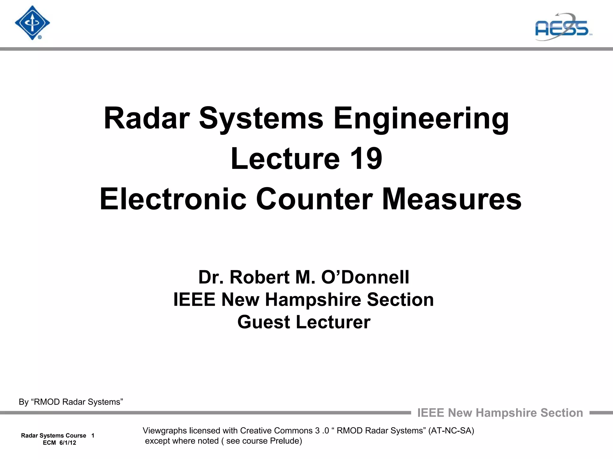
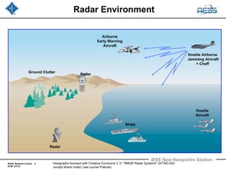
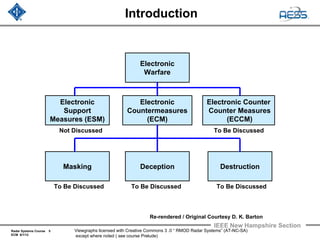
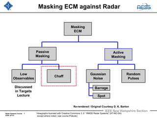
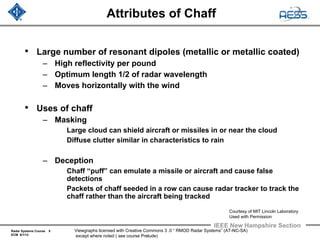
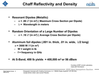
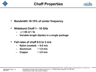
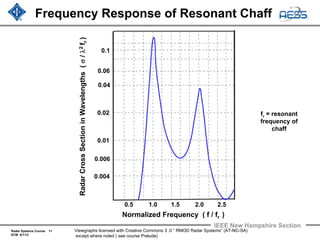
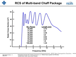
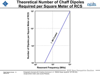
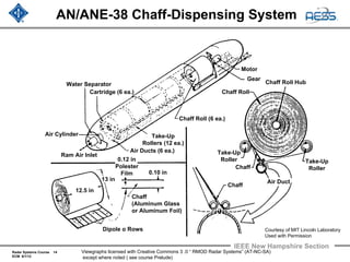
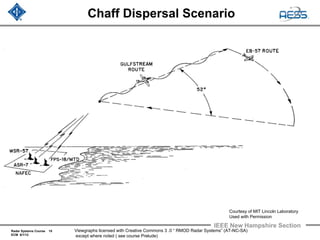
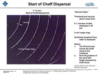
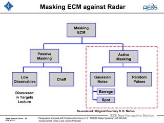
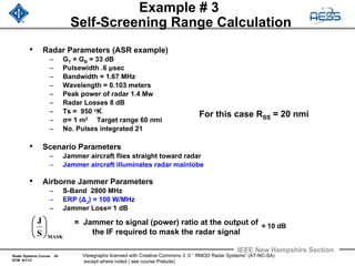
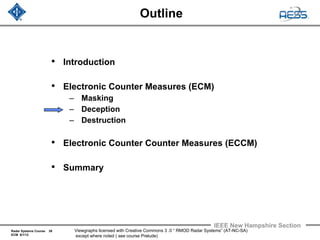
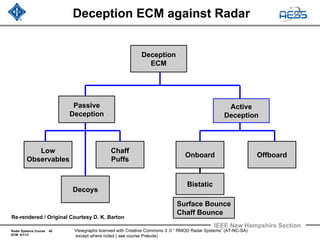
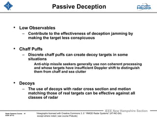
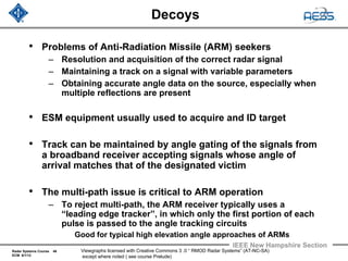
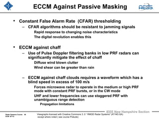
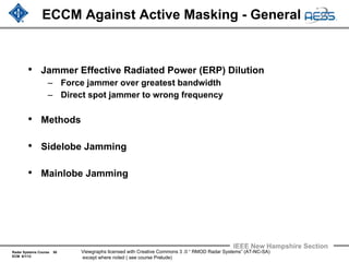
This document contains slides from a lecture on electronic countermeasures (ECM) against radar systems. It discusses how ECM techniques like chaff, noise jamming and random pulses can be used to mask targets from radar detection by increasing clutter. It provides details on how chaff works, including its reflectivity properties and how it is dispensed. Examples are given of chaff masking an aircraft and deceiving trackers. The presentation also introduces how electronic counter-countermeasures (ECCM) can be used to counter ECM techniques.
Radar is an object-detection system that uses radio waves to determine the range, angle, or velocity of objects. It can be used to detect aircraft, ships, spacecraft, guided missiles, motor vehicles, weather formations, and terrain. A radar system consists of a transmitter producing electromagnetic waves in the radio or microwaves domain, a transmitting antenna, a receiving antenna (often the same antenna is used for transmitting and receiving) and a receiver and processor to determine properties of the object(s).
RADAR - RAdio Detection And Ranging
This is the Part 1 of 2 of RADAR Introduction.
For comments please contact me at solo.hermelin@gmail.com.
For more presentation on different subjects visit my website at http://www.solohermelin.com.
Part of the Figures were not properly downloaded. I recommend viewing the presentation on my website under RADAR Folder.
RADAR - RAdio Detection And Ranging
This is the Part 2 of 2 of RADAR Introduction.
For comments please contact me at solo.hermelin@gmail.com.
For more presentation on different subjects visit my website at http://www.solohermelin.com.
Part of the Figures were not properly downloaded. I recommend viewing the presentation on my website under RADAR Folder.
RADAR - RAdio Detection And Ranging
This is the Part 1 of 2 of RADAR Introduction.
For comments please contact me at solo.hermelin@gmail.com.
For more presentation on different subjects visit my website at http://www.solohermelin.com.
Part of the Figures were not properly downloaded. I recommend viewing the presentation on my website under RADAR Folder.
RADAR - RAdio Detection And Ranging
This is the Part 2 of 2 of RADAR Introduction.
For comments please contact me at solo.hermelin@gmail.com.
For more presentation on different subjects visit my website at http://www.solohermelin.com.
Part of the Figures were not properly downloaded. I recommend viewing the presentation on my website under RADAR Folder.
Why Use SAW Sensors and Tags?
- Frequency/time are measured with greatest accuracy compared to any other physical measurement (10-10 - 10-14).
- External stimuli affects device parameters (frequency, phase, amplitude, delay)
- Operate from cryogenic to >1000oC
- Ability to both measure a stimuli and to wirelessly, passively transmit information
- Frequency range ~10 MHz – 3 GHz
- Monolithic structure fabricated with current IC photolithography techniques, small, rugged
The term “radar” is generally understood to mean a method by means of which short electromagnetic waves are used to detect distant objects and determine their location and movement. The term RADAR is an acronym from “RAdio Detection And Ranging”.
A complete radar measuring system is comprised of a transmitter with antenna, a transmission path, the reflecting target, a further transmission path (usually identical with the first one), and a receiver with antenna. Two separate antennas may be used, but often just one is used for both transmitting and receiving the radar signal.
Measuring the level of liquids or solids in vessels is a frequent requirement in industry. RADAR level measurement is the use of a radar signal is emitted via an antenna, reflected from the surface of the product and the echo received again after a time interval “t”.
This document, courtesy of KROHNE, is an excellent technical reference for a strong understanding of RADAR level measurement.
The proposed system aims at adapting the existing system and incorporating an algorithm to improve the efficiency of the autopilot. This is done with the help of two communication channels and a radar system. The radar system’s goal is to caution the driver of front and rear collision. All the channels and the radar system was designed and simulated. The yield analysis of each of the system was obtained using AWR.
Radar is a detection system that uses radio waves to determine the range, ang...vijay525469
Radar is a detection system that uses radio waves to determine the range,
angle, or velocity of objects. It can be used to
detect aircraft, ships, spacecraft, guided missiles,motor vehicles, weather
formations, and terrain.
Research Inventy : International Journal of Engineering and Science is published by the group of young academic and industrial researchers with 12 Issues per year. It is an online as well as print version open access journal that provides rapid publication (monthly) of articles in all areas of the subject such as: civil, mechanical, chemical, electronic and computer engineering as well as production and information technology. The Journal welcomes the submission of manuscripts that meet the general criteria of significance and scientific excellence. Papers will be published by rapid process within 20 days after acceptance and peer review process takes only 7 days. All articles published in Research Inventy will be peer-reviewed.
A Study on Protection of Cables by Solkor Differential Protection Relay with ...IJERA Editor
This paper intends to briefly compare the protection of buried three phase high voltage cable with Solkordifferential protection relay using metallic pilot wires orfibre optic pilot wires. Dielectric property of the fiber optic provides complete electrical isolation as well as interference free signaling. This provides total immunity from GPR (ground potential rise), longitudinal induction, and differential mode noise coupling andhigh-voltage hazards to personnel safety. So Fibre optic provides great advantage for Solkor differential protection relaying.
Similar to Radar 2009 a 19 electronic counter measures (20)
Overview of the fundamental roles in Hydropower generation and the components involved in wider Electrical Engineering.
This paper presents the design and construction of hydroelectric dams from the hydrologist’s survey of the valley before construction, all aspects and involved disciplines, fluid dynamics, structural engineering, generation and mains frequency regulation to the very transmission of power through the network in the United Kingdom.
Author: Robbie Edward Sayers
Collaborators and co editors: Charlie Sims and Connor Healey.
(C) 2024 Robbie E. Sayers
Final project report on grocery store management system..pdfKamal Acharya
In today’s fast-changing business environment, it’s extremely important to be able to respond to client needs in the most effective and timely manner. If your customers wish to see your business online and have instant access to your products or services.
Online Grocery Store is an e-commerce website, which retails various grocery products. This project allows viewing various products available enables registered users to purchase desired products instantly using Paytm, UPI payment processor (Instant Pay) and also can place order by using Cash on Delivery (Pay Later) option. This project provides an easy access to Administrators and Managers to view orders placed using Pay Later and Instant Pay options.
In order to develop an e-commerce website, a number of Technologies must be studied and understood. These include multi-tiered architecture, server and client-side scripting techniques, implementation technologies, programming language (such as PHP, HTML, CSS, JavaScript) and MySQL relational databases. This is a project with the objective to develop a basic website where a consumer is provided with a shopping cart website and also to know about the technologies used to develop such a website.
This document will discuss each of the underlying technologies to create and implement an e- commerce website.
About
Indigenized remote control interface card suitable for MAFI system CCR equipment. Compatible for IDM8000 CCR. Backplane mounted serial and TCP/Ethernet communication module for CCR remote access. IDM 8000 CCR remote control on serial and TCP protocol.
• Remote control: Parallel or serial interface.
• Compatible with MAFI CCR system.
• Compatible with IDM8000 CCR.
• Compatible with Backplane mount serial communication.
• Compatible with commercial and Defence aviation CCR system.
• Remote control system for accessing CCR and allied system over serial or TCP.
• Indigenized local Support/presence in India.
• Easy in configuration using DIP switches.
Technical Specifications
Indigenized remote control interface card suitable for MAFI system CCR equipment. Compatible for IDM8000 CCR. Backplane mounted serial and TCP/Ethernet communication module for CCR remote access. IDM 8000 CCR remote control on serial and TCP protocol.
Key Features
Indigenized remote control interface card suitable for MAFI system CCR equipment. Compatible for IDM8000 CCR. Backplane mounted serial and TCP/Ethernet communication module for CCR remote access. IDM 8000 CCR remote control on serial and TCP protocol.
• Remote control: Parallel or serial interface
• Compatible with MAFI CCR system
• Copatiable with IDM8000 CCR
• Compatible with Backplane mount serial communication.
• Compatible with commercial and Defence aviation CCR system.
• Remote control system for accessing CCR and allied system over serial or TCP.
• Indigenized local Support/presence in India.
Application
• Remote control: Parallel or serial interface.
• Compatible with MAFI CCR system.
• Compatible with IDM8000 CCR.
• Compatible with Backplane mount serial communication.
• Compatible with commercial and Defence aviation CCR system.
• Remote control system for accessing CCR and allied system over serial or TCP.
• Indigenized local Support/presence in India.
• Easy in configuration using DIP switches.
Saudi Arabia stands as a titan in the global energy landscape, renowned for its abundant oil and gas resources. It's the largest exporter of petroleum and holds some of the world's most significant reserves. Let's delve into the top 10 oil and gas projects shaping Saudi Arabia's energy future in 2024.
Cosmetic shop management system project report.pdfKamal Acharya
Buying new cosmetic products is difficult. It can even be scary for those who have sensitive skin and are prone to skin trouble. The information needed to alleviate this problem is on the back of each product, but it's thought to interpret those ingredient lists unless you have a background in chemistry.
Instead of buying and hoping for the best, we can use data science to help us predict which products may be good fits for us. It includes various function programs to do the above mentioned tasks.
Data file handling has been effectively used in the program.
The automated cosmetic shop management system should deal with the automation of general workflow and administration process of the shop. The main processes of the system focus on customer's request where the system is able to search the most appropriate products and deliver it to the customers. It should help the employees to quickly identify the list of cosmetic product that have reached the minimum quantity and also keep a track of expired date for each cosmetic product. It should help the employees to find the rack number in which the product is placed.It is also Faster and more efficient way.
NO1 Uk best vashikaran specialist in delhi vashikaran baba near me online vas...Amil Baba Dawood bangali
Contact with Dawood Bhai Just call on +92322-6382012 and we'll help you. We'll solve all your problems within 12 to 24 hours and with 101% guarantee and with astrology systematic. If you want to take any personal or professional advice then also you can call us on +92322-6382012 , ONLINE LOVE PROBLEM & Other all types of Daily Life Problem's.Then CALL or WHATSAPP us on +92322-6382012 and Get all these problems solutions here by Amil Baba DAWOOD BANGALI
#vashikaranspecialist #astrologer #palmistry #amliyaat #taweez #manpasandshadi #horoscope #spiritual #lovelife #lovespell #marriagespell#aamilbabainpakistan #amilbabainkarachi #powerfullblackmagicspell #kalajadumantarspecialist #realamilbaba #AmilbabainPakistan #astrologerincanada #astrologerindubai #lovespellsmaster #kalajaduspecialist #lovespellsthatwork #aamilbabainlahore#blackmagicformarriage #aamilbaba #kalajadu #kalailam #taweez #wazifaexpert #jadumantar #vashikaranspecialist #astrologer #palmistry #amliyaat #taweez #manpasandshadi #horoscope #spiritual #lovelife #lovespell #marriagespell#aamilbabainpakistan #amilbabainkarachi #powerfullblackmagicspell #kalajadumantarspecialist #realamilbaba #AmilbabainPakistan #astrologerincanada #astrologerindubai #lovespellsmaster #kalajaduspecialist #lovespellsthatwork #aamilbabainlahore #blackmagicforlove #blackmagicformarriage #aamilbaba #kalajadu #kalailam #taweez #wazifaexpert #jadumantar #vashikaranspecialist #astrologer #palmistry #amliyaat #taweez #manpasandshadi #horoscope #spiritual #lovelife #lovespell #marriagespell#aamilbabainpakistan #amilbabainkarachi #powerfullblackmagicspell #kalajadumantarspecialist #realamilbaba #AmilbabainPakistan #astrologerincanada #astrologerindubai #lovespellsmaster #kalajaduspecialist #lovespellsthatwork #aamilbabainlahore #Amilbabainuk #amilbabainspain #amilbabaindubai #Amilbabainnorway #amilbabainkrachi #amilbabainlahore #amilbabaingujranwalan #amilbabainislamabad
1. IEEE New Hampshire Section
Radar Systems Course 1
ECM 6/1/12
Viewgraphs licensed with Creative Commons 3 .0 “ RMOD Radar Systems” (AT-NC-SA)
except where noted ( see course Prelude)
Radar Systems Engineering
Lecture 19
Electronic Counter Measures
Dr. Robert M. O’Donnell
IEEE New Hampshire Section
Guest Lecturer
By “RMOD Radar Systems”
2. Radar Systems Course 2
ECM 6/1/12
IEEE New Hampshire Section
Viewgraphs licensed with Creative Commons 3 .0 “ RMOD Radar Systems” (AT-NC-SA)
except where noted ( see course Prelude)
Pulse
Compression
Receiver
Clutter Rejection
(Doppler Filtering)
A / D
Converter
Block Diagram of Radar System
Antenna
Propagation
Medium
Target
RCS
Transmitter
General Purpose Computer
Tracking
Data
Recording
Parameter
Estimation
Waveform
Generation
Detection
Power
Amplifier
T / R
Switch
Signal Processor Computer
Thresholding
User Displays and Radar Control
Photo Image
Courtesy of US Air Force
This lecture will cover techniques to
denigrate the performance of the radar from
other emitters, etc (jammers)
By “RMOD Radar Systems”
Aircraft
Transmitting
Jamming
Signals
3. Radar Systems Course 3
ECM 6/1/12
IEEE New Hampshire Section
Viewgraphs licensed with Creative Commons 3 .0 “ RMOD Radar Systems” (AT-NC-SA)
except where noted ( see course Prelude)
Outline
• Introduction
• Electronic Counter Measures (ECM)
• Electronic Counter Counter Measures (ECCM)
• Summary
By “RMOD Radar Systems”
4. Radar Systems Course 4
ECM 6/1/12
IEEE New Hampshire Section
Viewgraphs licensed with Creative Commons 3 .0 “ RMOD Radar Systems” (AT-NC-SA)
except where noted ( see course Prelude)
Radar Environment
Airborne
Early Warning
Aircraft
Hostile
Aircraft
Ships
Radar
Ground Clutter
Hostile Airborne
Jamming Aircraft
+ Chaff
Radar
5. Radar Systems Course 5
ECM 6/1/12
IEEE New Hampshire Section
Viewgraphs licensed with Creative Commons 3 .0 “ RMOD Radar Systems” (AT-NC-SA)
except where noted ( see course Prelude)
Introduction
Electronic
Warfare
Electronic Counter
Counter Measures
(ECCM)
Electronic
Countermeasures
(ECM)
Electronic
Support
Measures (ESM)
Masking DestructionDeception
Not Discussed
To Be Discussed
To Be Discussed
To Be DiscussedTo Be Discussed
Re-rendered / Original Courtesy D. K. Barton
7. Radar Systems Course 7
ECM 6/1/12
IEEE New Hampshire Section
Viewgraphs licensed with Creative Commons 3 .0 “ RMOD Radar Systems” (AT-NC-SA)
except where noted ( see course Prelude)
Masking ECM against Radar
Masking
ECM
Passive
Masking
Active
Masking
Chaff
Low
Observables
Gaussian
Noise
Random
Pulses
Discussed
in Targets
Lecture
Barrage
Spot
Re-rendered / Original Courtesy D. K. Barton
8. Radar Systems Course 8
ECM 6/1/12
IEEE New Hampshire Section
Viewgraphs licensed with Creative Commons 3 .0 “ RMOD Radar Systems” (AT-NC-SA)
except where noted ( see course Prelude)
Attributes of Chaff
• Large number of resonant dipoles (metallic or metallic coated)
– High reflectivity per pound
– Optimum length 1/2 of radar wavelength
– Moves horizontally with the wind
• Uses of chaff
– Masking
Large cloud can shield aircraft or missiles in or near the cloud
Diffuse clutter similar in characteristics to rain
– Deception
Chaff “puff” can emulate a missile or aircraft and cause false
detections
Packets of chaff seeded in a row can cause radar tracker to track the
chaff rather than the aircraft being tracked
Courtesy of MIT Lincoln Laboratory
Used with Permission
9. Radar Systems Course 9
ECM 6/1/12
IEEE New Hampshire Section
Viewgraphs licensed with Creative Commons 3 .0 “ RMOD Radar Systems” (AT-NC-SA)
except where noted ( see course Prelude)
Chaff Reflectivity and Density
• Resonant Dipoles (Metallic)
– σ = .86 λ2 (in m2) ( Maximum Cross Section per Dipole)
– λ = Wavelength in meters
• Random Orientation of a Large Number of Dipoles
– σ = .18 λ2 (in m2) ( Average Cross Section per Dipole)
• Aluminum foil dipoles (.001 in. thick, .01 in. wide, λ/2 long)
σ = 3000 W / f (in m2)
– W = weight in lb
– f = frequency in GHz
• At S-Band, 400 lb yields = 400,000 m2 or 56 dBsm
Courtesy of MIT Lincoln Laboratory
Used with Permission
10. Radar Systems Course 10
ECM 6/1/12
IEEE New Hampshire Section
Viewgraphs licensed with Creative Commons 3 .0 “ RMOD Radar Systems” (AT-NC-SA)
except where noted ( see course Prelude)
Chaff Properties
• Bandwidth 10-15% of center frequency
• Wideband Chaff 1 - 10 GHz
– σ = 60 m2 / lb
– Variable length dipoles in a single package
• Fall rates of chaff 0.5 to 3 m/s
– Nylon (coated) ~ 0.6 m/s
– Aluminum ~ 1.0 m/s
– Copper ~ 3.0 m/s
11. Radar Systems Course 11
ECM 6/1/12
IEEE New Hampshire Section
Viewgraphs licensed with Creative Commons 3 .0 “ RMOD Radar Systems” (AT-NC-SA)
except where noted ( see course Prelude)
Frequency Response of Resonant Chaff
0.5 1.0 1.5 2.0 2.5
Normalized Frequency ( f / fr )
RadarCrossSectioninWavelengths(σ/λ2fr)
0.01
0.006
0.004
0.1
0.06
0.04
0.02 fr = resonant
frequency of
chaff
13. Radar Systems Course 13
ECM 6/1/12
IEEE New Hampshire Section
Viewgraphs licensed with Creative Commons 3 .0 “ RMOD Radar Systems” (AT-NC-SA)
except where noted ( see course Prelude)
Theoretical Number of Chaff Dipoles
Required per Square Meter of RCS
NumberofDipolesperSquareMeterofRCS
Resonant Frequency (MHz)
103
1
MilCoated
104
103
102
102
101
104
14. Radar Systems Course 14
ECM 6/1/12
IEEE New Hampshire Section
Viewgraphs licensed with Creative Commons 3 .0 “ RMOD Radar Systems” (AT-NC-SA)
except where noted ( see course Prelude)
AN/ANE-38 Chaff-Dispensing System
Water Separator
Cartridge (6 ea.)
Air Cylinder
Ram Air Inlet
Take-Up
Rollers (12 ea.)
Air Ducts (6 ea.)
Chaff Roll (6 ea.)
Motor
Chaff Roll Hub
Chaff Roll
Gear
Chaff
(Aluminum Glass
or Aluminum Foil)
Air Duct
Chaff
Take-Up
Roller
Chaff
Take-Up
Roller
0.12 in
Polester
Film
12.5 in
13 in
0.10 in
Dipole o Rows Courtesy of MIT Lincoln Laboratory
Used with Permission
15. Radar Systems Course 15
ECM 6/1/12
IEEE New Hampshire Section
Viewgraphs licensed with Creative Commons 3 .0 “ RMOD Radar Systems” (AT-NC-SA)
except where noted ( see course Prelude)
Chaff Dispersal Scenario
Courtesy of MIT Lincoln Laboratory
Used with Permission
16. Radar Systems Course 16
ECM 6/1/12
IEEE New Hampshire Section
Viewgraphs licensed with Creative Commons 3 .0 “ RMOD Radar Systems” (AT-NC-SA)
except where noted ( see course Prelude)
Start of Chaff Dispersal
Courtesy of MIT Lincoln Laboratory
Used with Permission
“Normal Video”
Threshold just set just
above noise level
8 ½ minutes of data
displayed in 30
sec.
5 nmi range rings
Southeast quadrant from
radar is displayed
Notice:
1. The 30 knot wind
moves the chaff
cloud to the
northeast
2. How the gradient of
the wind with
height spreads the
chaff cloud
T = 0 min.
Start of Chaff Deployment
5 nmi. range rings
15 nmi.
17. Radar Systems Course 17
ECM 6/1/12
IEEE New Hampshire Section
Viewgraphs licensed with Creative Commons 3 .0 “ RMOD Radar Systems” (AT-NC-SA)
except where noted ( see course Prelude)
Movie of Chaff Dispersal
Courtesy of MIT Lincoln Laboratory
Used with Permission
“Normal Video”
Threshold just set just
above noise level
8 ½ minutes of data
displayed in 30
sec.
5 nmi range rings
Southeast quadrant from
radar is displayed
Notice:
1. The 30 knot wind
moves the chaff
cloud to the
northeast
2. How the gradient of
the wind with
height spreads the
chaff cloud
18. Radar Systems Course 18
ECM 6/1/12
IEEE New Hampshire Section
Viewgraphs licensed with Creative Commons 3 .0 “ RMOD Radar Systems” (AT-NC-SA)
except where noted ( see course Prelude)
Sequential PPI Displays of Chaff
Deployment and Drift by Wind
T = 6.7 min.
End of Chaff Deployment
T = 2.7 min.
T = 22 min.T = 14.5 min.
T = 1.2 min.
T = 0 min.
Start of Chaff Deployment
5 nmi. range rings
15 nmi.
30 nmi.
Courtesy of MIT Lincoln Laboratory Used with Permission
19. Radar Systems Course 19
ECM 6/1/12
IEEE New Hampshire Section
Viewgraphs licensed with Creative Commons 3 .0 “ RMOD Radar Systems” (AT-NC-SA)
except where noted ( see course Prelude)
Range - Height Displays of Chaff Cloud
WSR-57
Weather Radar
S-Band
Courtesy of MIT Lincoln Laboratory
Used with Permission
20. Radar Systems Course 20
ECM 6/1/12
IEEE New Hampshire Section
Viewgraphs licensed with Creative Commons 3 .0 “ RMOD Radar Systems” (AT-NC-SA)
except where noted ( see course Prelude)
Automated Tracker Output on Aircraft
During Chaff Exercise
Raw Radar Reports
Before Tracker
Scans
980 -1009
Tracker Output
3 Pulse MTI and
Sliding Window Detector
Tracker Output
Moving Target Detector (MTD)
(Pulse Doppler Processor)
Scans
1010 -1039
Two nmi
Range
Rings
21. Radar Systems Course 21
ECM 6/1/12
IEEE New Hampshire Section
Viewgraphs licensed with Creative Commons 3 .0 “ RMOD Radar Systems” (AT-NC-SA)
except where noted ( see course Prelude)
Radar Environment
Airborne
Early Warning
Aircraft
Hostile
Aircraft
Ships
Radar
Ground Clutter
Hostile Airborne
Jamming Aircraft
+ Chaff
Radar
22. Radar Systems Course 22
ECM 6/1/12
IEEE New Hampshire Section
Viewgraphs licensed with Creative Commons 3 .0 “ RMOD Radar Systems” (AT-NC-SA)
except where noted ( see course Prelude)
Masking ECM against Radar
Masking
ECM
Passive
Masking
Active
Masking
Chaff
Low
Observables
Gaussian
Noise
Random
Pulses
Discussed
in Targets
Lecture
Barrage
Spot
Re-rendered / Original Courtesy D. K. Barton
23. Radar Systems Course 23
ECM 6/1/12
IEEE New Hampshire Section
Viewgraphs licensed with Creative Commons 3 .0 “ RMOD Radar Systems” (AT-NC-SA)
except where noted ( see course Prelude)
US Radar Jamming Systems
• Jammers generate a noise-like signal in the radar’s frequency
band
• There are a number of different types of noise jamming which
will be examined
– Standoff, escort, and self screening jammers (location)
– Spot vs. barrage jamming (bandwidth)
US Air Force EF-111A Raven US Navy EA-6B Prowler
Courtesy of US NavyCourtesy of US Air Force
24. Radar Systems Course 24
ECM 6/1/12
IEEE New Hampshire Section
Viewgraphs licensed with Creative Commons 3 .0 “ RMOD Radar Systems” (AT-NC-SA)
except where noted ( see course Prelude)
Active Masking
• Receiver noise generally limits the sensitivity of most
microwave radars
– Raising the noise level with a jammer will further degrade the
sensitivity of the radar
– Strobe - in main lobe
– Massive false alarms - sidelobe jamming
• Spot Jammer
– A jammer whose noise energy is concentrated within the
receiver bandwidth
– Frequency agility of the radar will force the jammer to
distribute the jamming energy over a wide bandwidth
– A large number of similar radars in a geographic area may
also force the jammer to barrage mode
• Barrage Jammer
– A jammer which radiates over a wide band of frequencies
25. Radar Systems Course 25
ECM 6/1/12
IEEE New Hampshire Section
Viewgraphs licensed with Creative Commons 3 .0 “ RMOD Radar Systems” (AT-NC-SA)
except where noted ( see course Prelude)
Review - Radar Range Equation
Power density from
isotropic antenna
Power density from
directive antenna
Power density of echo
signal at radar
Power received
by radar
= peak transmitter
power
= transmit gain
= radar cross section
= effective area of
receiving antenna
= power received
2
T
E
2
T
TT
R
R4
A
R4
GP
P
π
σ
π
=
2
T
2
T
TT
R4R4
GP
π
σ
π
2
T
TT
R4
GP
π
2
T
T
R4
P
π
RP
TR
σ
EA
TG
26. Radar Systems Course 26
ECM 6/1/12
IEEE New Hampshire Section
Viewgraphs licensed with Creative Commons 3 .0 “ RMOD Radar Systems” (AT-NC-SA)
except where noted ( see course Prelude)
Review - Radar Range Equation
(continued)
Power received
by radar from target 2
T
E
2
T
TT
R
R4
A
R4
GP
P
π
σ
π
=
Target
Signal-to Noise Ratio
( ) NS
4
T
3
2
RTT
2
T
E
2
T
TT
N
R
BTkLR4
GGP
LR4
A
R4
GP
P
P
π
σλ
=
π
σ
π
=
Where: = Radar System Losses
= Receive Gain of Antenna
= Boltzmann Constant
L
k
RG
= Receiver Bandwidth
= System Noise Temperature
= Radar Wavelength
ST
λ
NB
Need to calculate
Target Signal-to (Noise + Interference) Ratio =
JN
R
PP
P
+ Jammer
Power
at
Radar
27. Radar Systems Course 27
ECM 6/1/12
IEEE New Hampshire Section
Viewgraphs licensed with Creative Commons 3 .0 “ RMOD Radar Systems” (AT-NC-SA)
except where noted ( see course Prelude)
Jammer Noise Power at Radar
JR
JL
JΔJammer Effective Power Density (W/MHz)
In the Receive Bandwidth of the Radar
( )JRJ G θΔJammer Effective Power Density
(W/MHz) from directive antenna
Jammer Power at Received at Radar
( )
( ) J
2
J
2
2
JJJ
J
LR4
G
P
π
λθΔ
=
= Jammer Receive Losses
= Range from Radar
to Jammer
( )JJG θ = Receive Gain in Jammer
Direction
( )
( )
( ) NSN
J
2
J
2
2
JJJ
4
T
3
2
RTT
NJ
R
BTkB
LR4
G
LR4
GGP
PP
P
+
π
λθΔ
π
σλ
=
+
Note: The Jammer Effective
Power Density includes the
effects of jammer system’s
antenna gain, rf jammer losses,
etc., that would alter the jammer
signal, that is transmitted toward
the radar to be jammed
28. Radar Systems Course 28
ECM 6/1/12
IEEE New Hampshire Section
Viewgraphs licensed with Creative Commons 3 .0 “ RMOD Radar Systems” (AT-NC-SA)
except where noted ( see course Prelude)
• Assumes Bandwidth of jamming pulse matched to that of
radar pulse
Jammer Radar Range Equation
(continued)
( )
( )
( ) NSN
J
2
J
2
2
JJJ
4
T
3
2
RTT
NJ
R
BTkB
LR4
G
LR4
GGP
PP
P
+
π
λθΔ
π
σλ
=
+
In many cases is much less than , therefore can be neglectedNP JP NP
( ) NJJJ
4
T
J
2
JRTT
J
R
BGLR4
LRGGP
P
P
J
S
θΔπ
σ
==
Then:
29. Radar Systems Course 29
ECM 6/1/12
IEEE New Hampshire Section
Viewgraphs licensed with Creative Commons 3 .0 “ RMOD Radar Systems” (AT-NC-SA)
except where noted ( see course Prelude)
Standoff Jamming
• To avoid producing a beacon like emission from the target,
masking jammers are operated from either standoff
platforms or from escort vehicles
• Standoff jammers operate at a range which places it
beyond the range of defensive systems supported by the
radar
– Orbits behind and/or side of the penetration corridor
– One standoff jammer may cover several radars
• For a stand off jammer within one beamwidth of the target,
the temperature due to the jammer often is 50 to 60 dB
greater than that of the receiver
30. Radar Systems Course 30
ECM 6/1/12
IEEE New Hampshire Section
Viewgraphs licensed with Creative Commons 3 .0 “ RMOD Radar Systems” (AT-NC-SA)
except where noted ( see course Prelude)
Example # 1a
Standoff Spot Mainlobe Jamming
• Radar Parameters (ASR example)
– GT = GR = 33 dB
– Pulsewidth .6 μsec
– Bandwidth = 1.67 MHz
– Wavelength = 0.103 meters
– Peak power of radar 1.4 Mw
– Radar Losses 8 dB
– Ts = 950 oK
– σ= 1 m2 Target range 60 nmi
– No. Pulses integrated 21
• Scenario Parameters
– Range from radar to jammer aircraft 100 nmi
– Range from radar to target 60 nmi
– Jammer aircraft illuminates radar mainlobe
• Airborne Standoff Jammer Parameters
– S-Band 2800 MHz
– ERP (ΔJ) = 1000 W/MHz
– Jammer Loss=1 dB
S/N = 14.4 dB
S/J = -4.1 dB
31. Radar Systems Course 31
ECM 6/1/12
IEEE New Hampshire Section
Viewgraphs licensed with Creative Commons 3 .0 “ RMOD Radar Systems” (AT-NC-SA)
except where noted ( see course Prelude)
Example # 1b
Standoff Barrage Sidelobe Jamming
• Radar Parameters (ASR example)
– GT = GR = 33 dB
– Pulsewidth .6 μsec
– Bandwidth = 1.67 MHz
– Wavelength = 0.103 meters
– Peak power of radar 1.4 Mw
– Radar Losses 8 dB
– Ts = 950 oK
– σ= 1 m2 Target range 60 nmi
– No. Pulses integrated 21
• Scenario Parameters
– Range from radar to jammer aircraft 100
– nmi
– Range from radar to target 60 nmi
– Jammer aircraft illuminates radar sidelobes
– Sidelobes down 23 dB from mainlobe
• Airborne Standoff Jammer Parameters
– S-Band 2800 MHz
– ERP (ΔJ) = 1000 W/MHz
– Jammer Loss=1 dB
S/N = 14.4 dB
S/J = 18.9 dB
32. Radar Systems Course 32
ECM 6/1/12
IEEE New Hampshire Section
Viewgraphs licensed with Creative Commons 3 .0 “ RMOD Radar Systems” (AT-NC-SA)
except where noted ( see course Prelude)
Example # 1c
Standoff Spot Sidelobe Jamming
• Radar Parameters (ASR example)
– GT = GR = 33 dB
– Pulsewidth .6 μsec
– Bandwidth = 1.67 MHz
– Wavelength = 0.103 meters
– Peak power of radar 1.4 Mw
– Radar Losses 8 dB
– Ts = 950 oK
– σ= 1 m2 Target range 60 nmi
– No. Pulses integrated 21
• Scenario Parameters
– Range from radar to jammer aircraft 100
– nmi
– Range from radar to target 60 nmi
– Jammer aircraft illuminates radar sidelobes
– Sidelobes down 55 dB from mainlobe
• Airborne Standoff Jammer Parameters
– S-Band 2800 MHz
– ERP (ΔJ) = 1000 W/MHz
– Jammer Loss=1 dB
S/N = 14.4 dB
S/J = 49.0 dB
Ultra-low sidelobes on radar
33. Radar Systems Course 33
ECM 6/1/12
IEEE New Hampshire Section
Viewgraphs licensed with Creative Commons 3 .0 “ RMOD Radar Systems” (AT-NC-SA)
except where noted ( see course Prelude)
Example # 1d
Standoff Barrage Sidelobe Jamming
• Radar Parameters (ASR example)
– GT = GR = 33 dB
– Pulsewidth .6 μsec
– Bandwidth = 1.67 MHz
– Wavelength = 0.103 meters
– Peak power of radar 1.4 Mw
– Radar Losses 8 dB
– Ts = 950 oK
– σ= 1 m2 Target range 60 nmi
– No. Pulses integrated 21
• Scenario Parameters
– Range from radar to jammer aircraft 100
– nmi
– Range from radar to target 60 nmi
– Jammer aircraft illuminates radar sidelobes
– Sidelobes down 23 dB from mainlobe
• Airborne Standoff Jammer Parameters
– S-Band 2800- 3000 MHz
– ERP (ΔJ) = 5 W/MHz
– Jammer Loss=1 dB
S/N = 14.4 dB
S/J = 41.9 dB
Jammer forced to transmit over 200 MHz
because of radar frequency hopping
34. Radar Systems Course 34
ECM 6/1/12
IEEE New Hampshire Section
Viewgraphs licensed with Creative Commons 3 .0 “ RMOD Radar Systems” (AT-NC-SA)
except where noted ( see course Prelude)
Escort Screening Jamming
• The escort screening jammer operates in a manner similar
to the standoff jammer, but accompanies the penetrating
raid, with some assigned range and cross range positions
• Calculation same as for standoff jammer
– Range and angle to target will vary with target range
reflecting approach of jammer with the raid
• Increasing the radar energy in the direction of the jammer in
the hope of increasing the radar echo power above the
jamming noise is called burn-through
– The range when this occurs is the “burn-through range”
• Escort screening jammer is a tougher problem than the
stand off jammer because the range is decreasing
– Received jammer energy increasing
35. Radar Systems Course 35
ECM 6/1/12
IEEE New Hampshire Section
Viewgraphs licensed with Creative Commons 3 .0 “ RMOD Radar Systems” (AT-NC-SA)
except where noted ( see course Prelude)
Example # 2a
Escort Spot Mainlobe Jamming
• Radar Parameters (ASR example)
– GT = GR = 33 dB
– Pulsewidth .6 μsec
– Bandwidth = 1.67 MHz
– Wavelength = 0.103 meters
– Peak power of radar 1.4 Mw
– Radar Losses 8 dB
– Ts = 950 oK
– σ= 1 m2 Target range 60 nmi
– No. Pulses integrated 21
• Scenario Parameters
– Range from radar to jammer aircraft 40 nmi
– Range from radar to target 40 nmi
– Jammer aircraft illuminates radar mainlobe
• Airborne Escort Jammer Parameters
– S-Band 2800 MHz
– ERP (ΔJ) = 100 W/MHz
– Jammer Loss=1 dB
S/N = 14.4 dB
S/J = -0.5 dB
Escort jammers usually have less power
than standoff jammers
36. Radar Systems Course 36
ECM 6/1/12
IEEE New Hampshire Section
Viewgraphs licensed with Creative Commons 3 .0 “ RMOD Radar Systems” (AT-NC-SA)
except where noted ( see course Prelude)
Example # 2b
Escort Barrage Mainlobe Jamming
• Radar Parameters (ASR example)
– GT = GR = 33 dB
– Pulsewidth .6 μsec
– Bandwidth = 1.67 MHz
– Wavelength = 0.103 meters
– Peak power of radar 1.4 Mw
– Radar Losses 8 dB
– Ts = 950 oK
– σ= 1 m2 Target range 60 nmi
– No. Pulses integrated 21
• Scenario Parameters
– Range from radar to jammer aircraft 60 nmi
– Range from radar to target 60 nmi
– Jammer aircraft illuminates radar mainlobe
• Airborne Escort Jammer Parameters
– S-Band 2800- 3000 MHz
– ERP (ΔJ) = 0.50 W/MHz
– Jammer Loss=1 dB
S/N = 14.4 dB
S/J = 22.5 dB
Jammer forced to transmit over 200 MHz
because of radar frequency hopping
Escort jammers usually have less power
than standoff jammers
37. Radar Systems Course 37
ECM 6/1/12
IEEE New Hampshire Section
Viewgraphs licensed with Creative Commons 3 .0 “ RMOD Radar Systems” (AT-NC-SA)
except where noted ( see course Prelude)
Self Screening Jamming
• “Self screening range” or “crossover range”
– Range when radar echo will exceed the jammer signal
Jammer power, received at radar, varies with inverse square of
the distance between the radar and the jammer
Radar echo power varies with inverse fourth power of the
distance between the radar and the jammer
– Even a small stand off jammer, operating in the barrage
mode, can guarantee masking of the target echo
= Jammer to signal (power) ratio at the output of the IF
required to mask the radar signal
MASKNJ
JRTT2
SS
S
J
BL4
LGGP
R ⎟
⎠
⎞
⎜
⎝
⎛
Δπ
σ
=
MASKS
J
⎟
⎠
⎞
⎜
⎝
⎛
38. Radar Systems Course 38
ECM 6/1/12
IEEE New Hampshire Section
Viewgraphs licensed with Creative Commons 3 .0 “ RMOD Radar Systems” (AT-NC-SA)
except where noted ( see course Prelude)
Example # 3
Self-Screening Range Calculation
• Radar Parameters (ASR example)
– GT = GR = 33 dB
– Pulsewidth .6 μsec
– Bandwidth = 1.67 MHz
– Wavelength = 0.103 meters
– Peak power of radar 1.4 Mw
– Radar Losses 8 dB
– Ts = 950 oK
– σ= 1 m2 Target range 60 nmi
– No. Pulses integrated 21
• Scenario Parameters
– Jammer aircraft flies straight toward radar
– Jammer aircraft illuminates radar mainlobe
• Airborne Jammer Parameters
– S-Band 2800 MHz
– ERP (ΔJ) = 100 W/MHz
– Jammer Loss= 1 dB
= Jammer to signal (power) ratio at the output of
the IF required to mask the radar signal
MASKS
J
⎟
⎠
⎞
⎜
⎝
⎛ ≈ 10 dB
For this case RSS = 20 nmi
40. Radar Systems Course 40
ECM 6/1/12
IEEE New Hampshire Section
Viewgraphs licensed with Creative Commons 3 .0 “ RMOD Radar Systems” (AT-NC-SA)
except where noted ( see course Prelude)
Deception ECM against Radar
Deception
ECM
Passive
Deception
Active
Deception
Chaff
Puffs
Low
Observables
Onboard Offboard
Bistatic
Decoys
Surface Bounce
Chaff Bounce
Re-rendered / Original Courtesy D. K. Barton
41. Radar Systems Course 41
ECM 6/1/12
IEEE New Hampshire Section
Viewgraphs licensed with Creative Commons 3 .0 “ RMOD Radar Systems” (AT-NC-SA)
except where noted ( see course Prelude)
Passive Deception
• Low Observables
– Contribute to the effectiveness of deception jamming by
making the target less conspicuous
• Chaff Puffs
– Discrete chaff puffs can create decoy targets in some
situations
Anti-ship missile seekers generally use non coherent processing
and whose targets have insufficient Doppler shift to distinguish
them from chaff and sea clutter
• Decoys
– The use of decoys with radar cross section and motion
matching those of real targets can be effective against all
classes of radar
42. Radar Systems Course 42
ECM 6/1/12
IEEE New Hampshire Section
Viewgraphs licensed with Creative Commons 3 .0 “ RMOD Radar Systems” (AT-NC-SA)
except where noted ( see course Prelude)
Active Deception
• A repeater jammer generates false echoes by delaying the
received signals and re-transmitting at slightly later times
• Delaying the signals causes them to appear at different
ranges and azimuths
• Types of repeater jammers
– A transponder repeater plays back a stored replica of the
radar signal after it is triggered by the radar
– A range gate stealer is a repeater jammer whose function is
to cause a tracking radar to “break lock”on the target
Delay of jamming pulses slowly changed, from delay of echo of
the radar pulse, causing radar to track the repeater pulses
– A velocity gate stealer transmits a signal which falsifies the
targets speed or pretends that it is stationary
43. Radar Systems Course 43
ECM 6/1/12
IEEE New Hampshire Section
Viewgraphs licensed with Creative Commons 3 .0 “ RMOD Radar Systems” (AT-NC-SA)
except where noted ( see course Prelude)
Active Deception (continued)
• Repeater jammers can be very effective against an
unprepared radar system
– Relatively easy to counter
• Special purpose jammers require detailed knowledge of
radar
– Details are beyond the scope of this lecture
45. Radar Systems Course 45
ECM 6/1/12
IEEE New Hampshire Section
Viewgraphs licensed with Creative Commons 3 .0 “ RMOD Radar Systems” (AT-NC-SA)
except where noted ( see course Prelude)
Destructive ECM against Radar
Destructive
ECM
Anti-radiation
Missiles
High Power
Microwave
Decoys
Surface Bounce
Intercept and Destroy
Shielding
EMC Discipline
EMP Protection
Re-rendered / Original Courtesy D. K. Barton
46. Radar Systems Course 46
ECM 6/1/12
IEEE New Hampshire Section
Viewgraphs licensed with Creative Commons 3 .0 “ RMOD Radar Systems” (AT-NC-SA)
except where noted ( see course Prelude)
Decoys
• Problems of Anti-Radiation Missile (ARM) seekers
– Resolution and acquisition of the correct radar signal
– Maintaining a track on a signal with variable parameters
– Obtaining accurate angle data on the source, especially when
multiple reflections are present
• ESM equipment usually used to acquire and ID target
• Track can be maintained by angle gating of the signals from
a broadband receiver accepting signals whose angle of
arrival matches that of the designated victim
• The multi-path issue is critical to ARM operation
– To reject multi-path, the ARM receiver typically uses a
“leading edge tracker”, in which only the first portion of each
pulse is passed to the angle tracking circuits
Good for typical high elevation angle approaches of ARMs
47. Radar Systems Course 47
ECM 6/1/12
IEEE New Hampshire Section
Viewgraphs licensed with Creative Commons 3 .0 “ RMOD Radar Systems” (AT-NC-SA)
except where noted ( see course Prelude)
Outline
• Introduction
• Electronic Counter Measures (ECM)
• Electronic Counter Counter Measures (ECCM)
– Masking
Passive
Active
– Deception
– Destruction
• Summary
48. Radar Systems Course 48
ECM 6/1/12
IEEE New Hampshire Section
Viewgraphs licensed with Creative Commons 3 .0 “ RMOD Radar Systems” (AT-NC-SA)
except where noted ( see course Prelude)
ECCM Against Passive Masking
• Constant False Alarm Rate (CFAR) thresholding
– CFAR algorithms should be resistant to jamming signals
Rapid response to changing noise characteristics
The digital revolution enables this
• ECCM against chaff
– Use of Pulse Doppler filtering banks in low PRF radars can
significantly mitigate the effect of chaff
Diffuse wind blown clutter
Wind shear can be greater than rain
– ECCM against chaff clouds requires a waveform which has a
blind speed in excess of 100 m/s
Forces microwave radar to operate in the medium or high PRF
mode with constant PRF bursts, or in the CW mode
UHF and lower frequencies can use staggered PRF with
unambiguous range detection
Propagation limitations
49. Radar Systems Course 49
ECM 6/1/12
IEEE New Hampshire Section
Viewgraphs licensed with Creative Commons 3 .0 “ RMOD Radar Systems” (AT-NC-SA)
except where noted ( see course Prelude)
Outline
• Introduction
• Electronic Counter Measures (ECM)
• Electronic Counter Counter Measures (ECCM)
– Masking
Passive
Active
– Deception
– Destruction
• Summary
50. Radar Systems Course 50
ECM 6/1/12
IEEE New Hampshire Section
Viewgraphs licensed with Creative Commons 3 .0 “ RMOD Radar Systems” (AT-NC-SA)
except where noted ( see course Prelude)
ECCM Against Active Masking - General
• Jammer Effective Radiated Power (ERP) Dilution
– Force jammer over greatest bandwidth
– Direct spot jammer to wrong frequency
• Methods
• Sidelobe Jamming
• Mainlobe Jamming
51. Radar Systems Course 51
ECM 6/1/12
IEEE New Hampshire Section
Viewgraphs licensed with Creative Commons 3 .0 “ RMOD Radar Systems” (AT-NC-SA)
except where noted ( see course Prelude)
ECCM Against Active Masking -
Methods
• Frequency agility and diversity
– Burst to burst frequency agility may be sufficient
– Use of parallel frequency diverse channels
• Wideband transmissions
– Will force the jammer to a barrage mode
• Polarization methods
– Since most jammers transmit circular polarization or linear at
45 degrees, two orthogonal receive channels can result in
one channel orthogonal to the jammer
• Deceptive transmissions
– Small off frequency (out of regular band) signals can be
transmitted force the jammer much more broadband than the
radar operates (good if jammer is in sidelobes)
52. Radar Systems Course 52
ECM 6/1/12
IEEE New Hampshire Section
Viewgraphs licensed with Creative Commons 3 .0 “ RMOD Radar Systems” (AT-NC-SA)
except where noted ( see course Prelude)
ECCM Against Active Masking -
Sidelobe Jamming
• Sidelobe Jamming
– Low and Ultra Low Sidelobe Antennas
Can be reduced to -50 dB or less
These levels of sidelobe response make it extremely difficult for
barrage jammers to raise the radar noise level by significant
amounts
For ground based radar sites, ground reflections control the
achievable sidelobe levels
– Coherent sidelobe cancellers
Auxiliary antenna and receiver generate adaptive signal which
cancels jamming entering main receiver
This increases sidelobes at other angles (use with caution)
– Fully adaptive antennas permit both low sidelobes and
sidelobe cancellation
53. Radar Systems Course 53
ECM 6/1/12
IEEE New Hampshire Section
Viewgraphs licensed with Creative Commons 3 .0 “ RMOD Radar Systems” (AT-NC-SA)
except where noted ( see course Prelude)
ECCM against Active Masking -
Mainlobe Jamming
• Require at least one antenna channel, independent of the
main channel, with comparable gain
• Fully adaptive array meets this requirement with significant
expense
55. Radar Systems Course 55
ECM 6/1/12
IEEE New Hampshire Section
Viewgraphs licensed with Creative Commons 3 .0 “ RMOD Radar Systems” (AT-NC-SA)
except where noted ( see course Prelude)
ECCM against Deception
• Passive Deception
– Adequate number of detection and tracking channels to
process the false targets while maintaining detection and
track on true targets
– Non-Cooperative Identification (NCID) techniques
High Range Resolution techniques
Doppler spectral analysis
Multiple frequency analysis of target RCS
Target trajectory analysis, etc, etc etc
• Active Deception
– Ultra low sidelobe antennas
– Sidelobe blanking
– Receiver fixes
– Monopulse radar fixes
Parallel channels with different time constants for AGC
– Avoid hardware deficiencies
57. Radar Systems Course 57
ECM 6/1/12
IEEE New Hampshire Section
Viewgraphs licensed with Creative Commons 3 .0 “ RMOD Radar Systems” (AT-NC-SA)
except where noted ( see course Prelude)
ECCM against Destructive ECM
• Destroy them with a SAM or AAM
• Destructive techniques
– Low Probability of Intercept Radar
Use unusual waveforms (Code modulated, CW, impulses)
It is widely postulated that these waveforms cannot be detected or
acquired by an ARM receiver designed to work against
conventional short pulse or CW radars
– Active decoys
Placement of decoys surrounding the radar and emiting similar
signals can present the ARM with a confusing target
Defensive equivalent of multiple blinking jammers
– Bistatic jamming
Illumination of the surrounding terrain by the radar main lobe can
create the equivalent of multiple decoys
Radar pulse must have a gradually increasing leading edge to prevent
ARM from using leading edge gate gating to reject the multipath
58. Radar Systems Course 58
ECM 6/1/12
IEEE New Hampshire Section
Viewgraphs licensed with Creative Commons 3 .0 “ RMOD Radar Systems” (AT-NC-SA)
except where noted ( see course Prelude)
Summary
• Electronically active and passive techniques have been
described , which can potentially degrade the performance
of microwave radar systems
• Passive techniques – Chaff, decoys
• Active techniques
– Jammers generate a noise-like signal in the radar’s frequency
band
– There are a number of different types of noise jamming which
will be examined
Standoff, escort, and self screening jammers (location)
Spot vs. barrage jamming (bandwidth)
– Repeater jammers were also examined
• Techniques have been developed which mitigate these ECM
techniques (ECCM) and are discussed to some degree
59. Radar Systems Course 59
ECM 6/1/12
IEEE New Hampshire Section
Viewgraphs licensed with Creative Commons 3 .0 “ RMOD Radar Systems” (AT-NC-SA)
except where noted ( see course Prelude)
References
1. Barton, D. K. , Radar Countermeasure Issues, Lecture notes,
presented at MIT Lincoln Laboratory, 17 March 1995
2. Skolnik, M., Introduction to Radar Systems, New York,
McGraw-Hill, 3rd Edition, 2001
3. Skolnik, M., Editor in Chief, Radar Handbook, New York,
McGraw-Hill, 3rd Ed., 2008
4. Skolnik, M., Editor in Chief, Radar Handbook, New York,
McGraw-Hill, 2nd Ed., 1990
5. Evaluation of the Performance of the Moving Target Detector
(MTD) in ECM and Chaff, MIT Lincoln Laboratory, Technical
Note 1976-17, 25 March 1976
6. Nathanson, F. E., Radar Design Principles, Sci-Tech, 2nd Ed.
1999
By “RMOD Radar Systems”
60. Radar Systems Course 60
ECM 6/1/12
IEEE New Hampshire Section
Viewgraphs licensed with Creative Commons 3 .0 “ RMOD Radar Systems” (AT-NC-SA)
except where noted ( see course Prelude)
Acknowledgements
• David K. Barton
By “RMOD Radar Systems”
61. Radar Systems Course 61
ECM 6/1/12
IEEE New Hampshire Section
Viewgraphs licensed with Creative Commons 3 .0 “ RMOD Radar Systems” (AT-NC-SA)
except where noted ( see course Prelude)
Problems
• 1 A C-Band (wavelength = 5.5 cm) pencil beam radar has
peak power of 1 MW, 1 μsec pulsewidth. Its antenna
diameter is 5 meters diameter and has an efficiency of 0.6.
The system noise temperature is 825oK and the total system
losses are 7 dB. What is the S/N(in dB) for a single pulse on
a 1 m2 target at a range of 150 nmi?
• 2. If a mainlobe jammer has an ERP of 300 w/MHz and 1 dB
jammer losses and is located at 125 nmi from the radar,
what is the S/J (in dB) ratio for a single pulse on a 1 m2
target at a range of 150 nmi? (For problems 2 through 5)
assume that the bandwidth of the jammer and the radar are
matched (BJ = BN)
• 3. What is the S/(N+J) for the scenario and radar?
62. Radar Systems Course 62
ECM 6/1/12
IEEE New Hampshire Section
Viewgraphs licensed with Creative Commons 3 .0 “ RMOD Radar Systems” (AT-NC-SA)
except where noted ( see course Prelude)
Problems
• 4.For the mainlobe jamming scenario and parameters in
problem 2, what in the Self-Screening range (in nmi)?
Assume
5. If a jammer illuminates the above radar’s sidelobes (assume
they are 24 dB down from the mainlobe) and the jammer has
an ERP of 250 w/MHz, 1 dB jammer losses and is located 50
nmi from the radar, what is the S/(N+J) (in dB) ratio for a
single pulse on a 1 m2 target at a range of 150 nmi?
dB10
S
J
MASK
=⎟
⎠
⎞
⎜
⎝
⎛