This document discusses different types of antenna jobs and areas of research. It describes three main sectors for antenna jobs: private sector working for consumer electronics companies, defense department/government jobs, and university/research jobs. It provides details on the responsibilities for each type of private sector job and notes that defense and government jobs focus more on research and integration. University/research jobs primarily involve publishing research and involve some teaching. Active areas of antenna research mentioned include meta-materials, electromagnetic solvers, miniaturization, and array optimization.
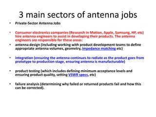


![Electromagnetic Spectrum
• The Electromagnetic Spectrum covers a very wide range of frequency,
from almost DC to gamma rays.
• Radio frequency (RF) is a subset of the EM spectrum and is loosely
defined as:
“The frequency in the portion of the electromagnetic spectrum that is
between the audio-frequency portion and the infrared portion. The present
practical limits of radio frequency are roughly 10 kHz to 100 GHz.” [IEEE
Std 100-1988 Standard Dictionary of Electrical and Electronic Terms]
• EM (Electromagnetic) waves can propagate in vacuum but not acoustic
waves.
40](https://image.slidesharecdn.com/antennafundamentalsnew-converted-190714192613/85/EC6602-Antenna-fundamentals-40-320.jpg)