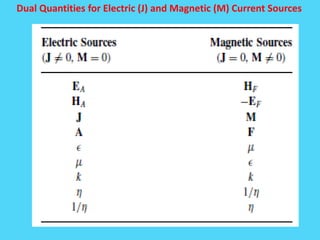
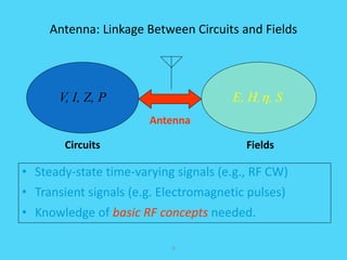
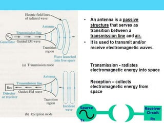
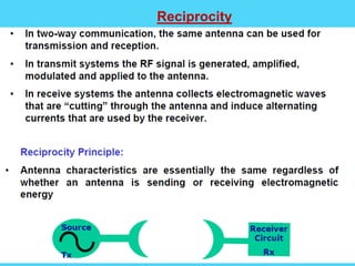
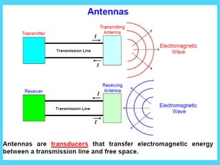
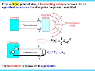
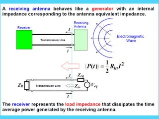
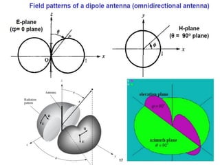
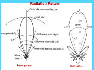
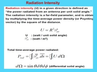
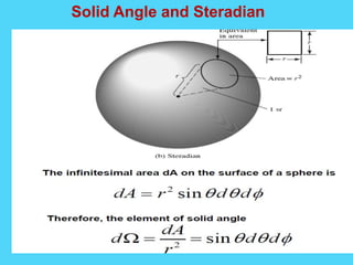
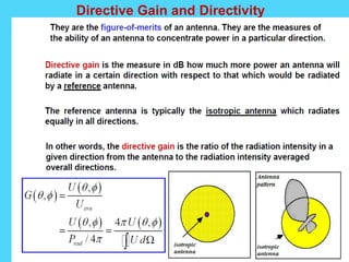
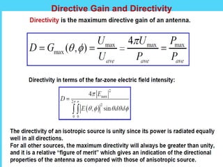
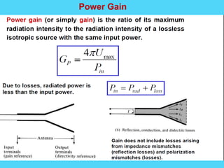
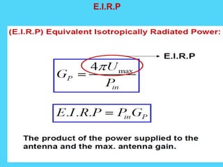
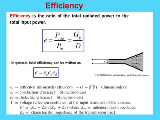
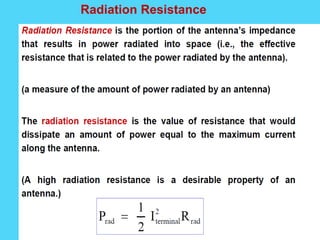
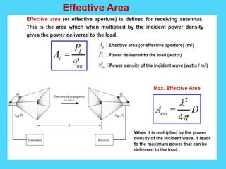
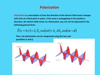
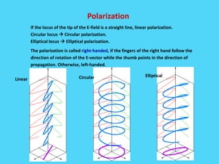
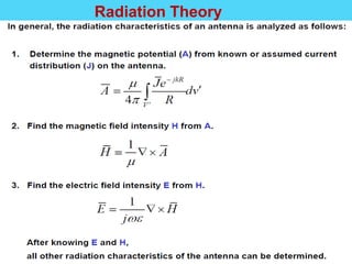
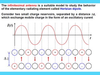
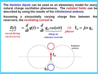
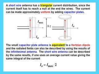
This document discusses electromagnetic radiation and antenna fundamentals. It begins by defining an antenna as a transducer between transmission lines and the surrounding medium that allows efficient launching of electromagnetic waves. The key characteristics of antennas like frequency, mounting location, gain, polarization, and efficiency are discussed. The document then covers topics such as radiation patterns, directivity, power gain, near fields, far fields, and polarization. Dipole antennas and the Friis transmission equation are also summarized.

![Electromagnetic Spectrum
4
• The Electromagnetic Spectrum covers a very wide range of frequency,
from almost DC to gamma rays.
• Radio frequency (RF) is a subset of the EM spectrum and is loosely
defined as:
“The frequency in the portion of the electromagnetic spectrum that is
between the audio-frequency portion and the infrared portion. The present
practical limits of radio frequency are roughly 10 kHz to 100 GHz.” [IEEE
Std 100-1988 Standard Dictionary of Electrical and Electronic Terms]
• EM (Electromagnetic) waves can propagate in vacuum but not acoustic
waves.](https://image.slidesharecdn.com/antennaunit1-converted-190714192402/85/EC6602-AWP-unit-1-4-320.jpg)


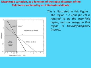

![Magnitude variation, as a function of the radial distance, of the
field terms radiated by an infinitesimal dipole.
The sphere with radius equal to the radiandistan ce
(r = λ/2π) is referred as the radian sphere, and it
defines the region within which the reactive power
density is greater than the radiated power density .
For an antenna, the radian sphere represents the
volume occupied mainly by the stored energy of the
antenna’s electric and magnetic fields. Outside the
radian sphere the radiated power density is greater
than the reactive power density and begins to
dominate as r > λ/2π. Therefore the radian sphere
can be used as a reference, and it defines the
transition between stored energy pulsating
primarily in the ±θ direction and energy radiating in
the radial (r) direction [represented by the first term
the second term represents stored energy pulsating
inwardly and outwardly in the radial (r) direction].
Similar behavior, where the power density near the
antenna is primarily reactive and far away is
primarily real, is exhibited by all antennas, although
not exactly at the radiandistance.](https://image.slidesharecdn.com/antennaunit1-converted-190714192402/85/EC6602-AWP-unit-1-66-320.jpg)