This document discusses transformer per unit calculations and different three-phase transformer connections. It includes the following:
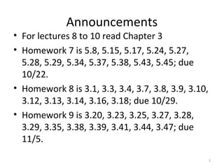
- Homework assignments for chapters 3 and 5 are announced, due on various dates from 10/22 to 11/5.
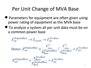
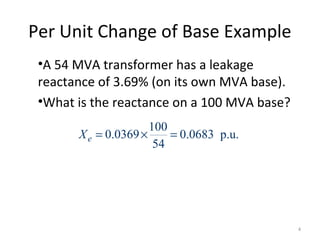
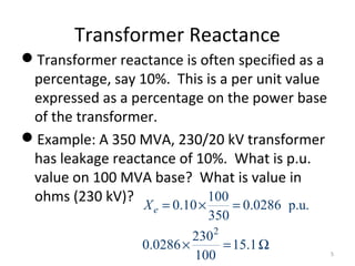
- Per unit calculations are used to convert transformer parameters given on one power base to a common power base for system analysis. An example conversion from 54 MVA base to 100 MVA base is shown.
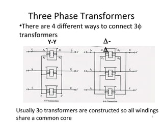
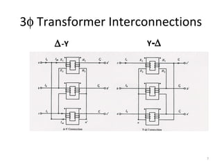
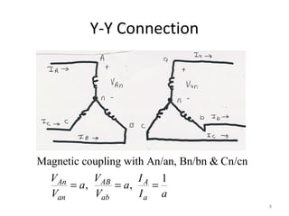
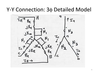
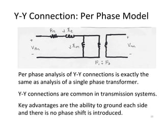
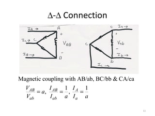
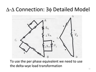
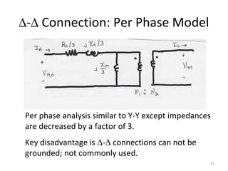
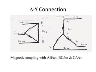
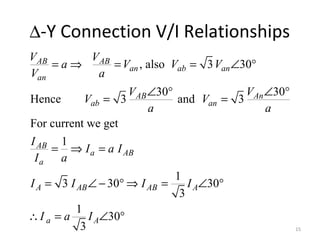
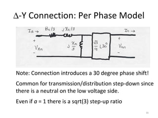
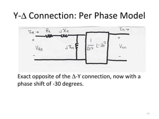
- The four different three-phase transformer connections are presented: Y-Y, Δ-Δ, Δ-Y, and Y-Δ. Detailed models and per-phase equivalents are derived for each. Phase shifts introduced by the Δ-Y and Y-Δ