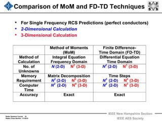
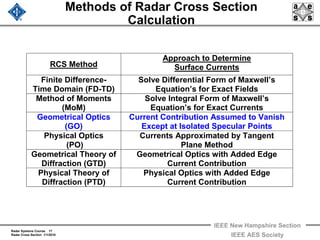
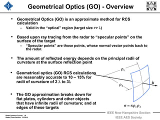
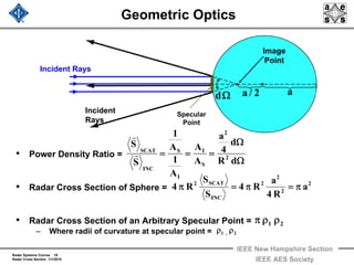
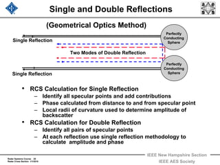
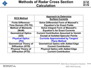
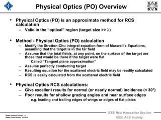
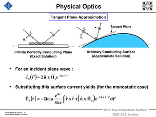
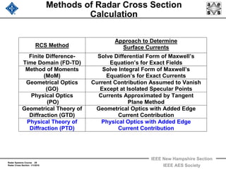
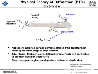
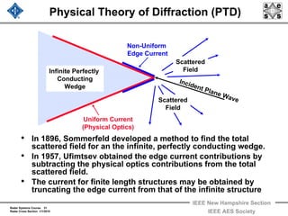
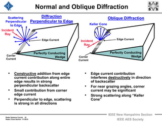
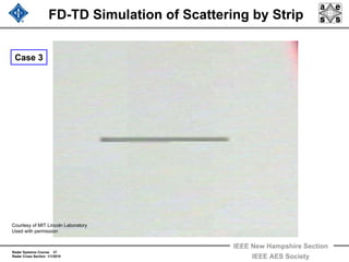
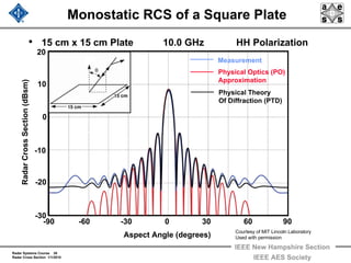
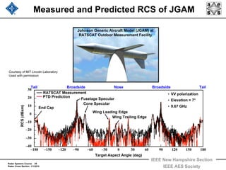
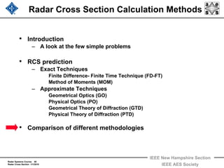
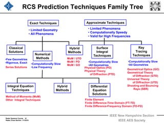
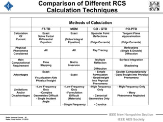
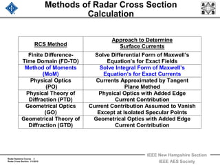
This document discusses various methods for calculating radar cross section (RCS), including the finite difference time domain method, method of moments, geometrical optics, physical optics, geometrical theory of diffraction, and physical theory of diffraction. It provides overviews and comparisons of each method, explaining their approaches and areas of applicability. The document also includes examples of RCS calculations and summaries of key points about specific methods.

![Radar Systems Course 7
Radar Cross Section 1/1/2010
IEEE New Hampshire Section
IEEE AES Society
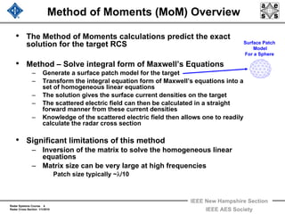
Method of Moments
• Maxwell’s Equations transform to the Stratton and Chu
Equations using the vector Green’s Theorem and yield:
• Free space Green’s function is an spherical wave falling of
as:
• Also, note:
( ) ( ) ( )[ ]
( ) ( ) ( )[ ]
rrR
R4
e
SdHnˆxHxnˆExnˆiH
SdEnˆxExnˆHxnˆiE
ikR
'S
S
'S
S
′−==⎥
⎦
⎤
⎢
⎣
⎡
π
=ψ
′ψ∇⋅−ψ∇−ψεω+=
′ψ∇⋅+ψ∇+ψμω+=
+
∫∫
∫∫
rrrrrr
rrrrrr
Free Space
Green’s Function
SI
SI
HHH
EEE
rrr
rrr
+=
+=
R/1](https://image.slidesharecdn.com/radar-2009-a7-radar-cross-section-2-160213204216/85/Radar-2009-a-7-radar-cross-section-2-7-320.jpg)
![Radar Systems Course 8
Radar Cross Section 1/1/2010
IEEE New Hampshire Section
IEEE AES Society
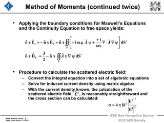
Method of Moments (continued once)
• On the surface of the perfectly conducting target these
equations become:
– Total tangential electric field zero at surface
– No magnetic sources of currents or charges as source of
scattered fields
• Electric Field Integral Equation (EFIE)
• Magnetic Field Integral Equation (MFIE)
• Causes of scattered fields
– Scattered electric field – electric currents and charges
– Scattered magnetic field – electric currents
∫∫∫∫ ′′
′ψ∇=′ψ∇=
SS
S SdxJSdx)Hxnˆ(H
rrr
[ ] Sd
1
JiSd)Enˆ()Hxnˆ(iE
SS
S
′⎥
⎦
⎤
⎢
⎣
⎡
ψ∇ρ
ε
+ψμω+=′ψ∇⋅+ψμω+= ∫∫∫∫ ′′
rrr](https://image.slidesharecdn.com/radar-2009-a7-radar-cross-section-2-160213204216/85/Radar-2009-a-7-radar-cross-section-2-8-320.jpg)
![Radar Systems Course 11
Radar Cross Section 1/1/2010
IEEE New Hampshire Section
IEEE AES Society
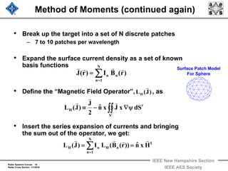
Method of Moments (one last time)
• Multiply by the weighting vector, , and integrating over
the surface:
– Point Testing
– Galerkin’s Method
• This is a set of N equations in N unknowns (current
coefficients, ) of the form:
• The only difficulty is inversion of a very large matrix
( )[ ] 0dSSd))r(B(LWiIdSHxnˆ)r(W n
S
m
'S
N
1n
n
S
I
=′⋅μω−⋅ ∫∫∫∫∑∫∫ =
rrrrr
mW
r
VIZ
vrrr
=
)r(BW mm
rrr
=
)rr(W mm
rrr
−δ=
mI
VZI 1
vrrr −
=
N...,3,2,1m =](https://image.slidesharecdn.com/radar-2009-a7-radar-cross-section-2-160213204216/85/Radar-2009-a-7-radar-cross-section-2-11-320.jpg)