TCL 3205: AntennaEngineering
BACHELOR OF ENGINEERING HONOURS
DEGREE IN TELECOMMUNICATIONS ENGINEERING
2.
REFERENCE TEXTS
John DKraus, Ronald J Marhefka, Ahmed S Khan “Antenna and
wave propagation” 4th Edition 2010
Constantine Balanis. A, “Antenna Theory: Analysis and Design”,
3rd Edition, John Wiley and Sons, 2012.
Abdollah Ghasemi, Ali Abedi, Farshid Ghasemi, “Propagation
Engineering in a Radio Links Design”, Springer Science + Business
media, New York, 2013.
Stutzman, Warren L, Gary A.Thiele, “Antenna theory and design”,
3rd Edition, John Wiley and Sons 2012
Ghasemi, A., Abedi, A. and Ghasemi, F., 2013. Propagation
engineering in radio links design. Springer Science & Business
Media.
Prasad, K.D. and Handa, D., 2003. Antenna and wave propagation.
Satya Prakashan.
Assessment Scheme
Course natureTheory
Assessment Method (Weightage
100%)
In-semester
Assessme
nt tool
Test I
Unit I&II
Test II
Unit
III&IV
Test III
Unit I to
IV
Assignme
nt I Assignmen
t II
Total
Weightag
e
5% 5% 5% 5% 5% 25%
Final Exam End of Semester Examination Weightage : 75%
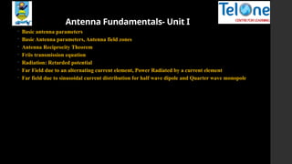
Antenna Fundamentals- UnitI
Basic antenna parameters
Basic Antenna parameters, Antenna field zones
Antenna Reciprocity Theorem
Friis transmission equation
Radiation: Retarded potential
Far Field due to an alternating current element, Power Radiated by a current element
Far field due to sinusoidal current distribution for half wave dipole and Quarter wave monopole
7.
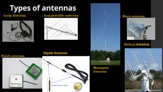
Introduction
A brief overviewof contemporary antenna types used
cellular,
communication links
satellite communication
radar,
other microwave and
millimeter wave systems
Microwave is presumed to cover the frequency spectrum from 800 MHz to 94 GHz
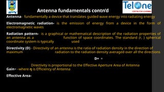
Antenna fundamentals contn’d
Antenna-fundamentally a device that translates guided wave energy into radiating energy
Electromagnetic radiation- is the emission of energy from a device in the form of
electromagnetic waves
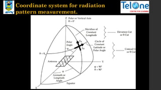
Radiation pattern- is a graphical or mathematical description of the radiation properties of
an antenna as a function of space coordinates. The standard (r, ) spherical
coordinate system is typically used
Directivity (D) - Directivity of an antenna is the ratio of radiation density in the direction of
maximum radiation to the radiation density averaged over all the directions
D= =
Directivity is proportional to the Effective Aperture Area of Antenna
Gain= -where η is Efficiency of Antenna
Effective Area-
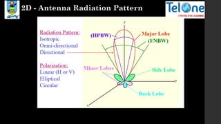
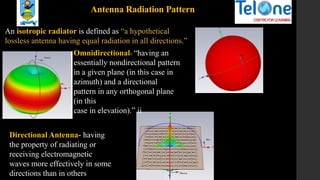
Antenna Radiation Pattern
Anisotropic radiator is defined as “a hypothetical
lossless antenna having equal radiation in all directions.”
Directional Antenna- having
the property of radiating or
receiving electromagnetic
waves more effectively in some
directions than in others
Omnidirectional- “having an
essentially nondirectional pattern
in a given plane (in this case in
azimuth) and a directional
pattern in any orthogonal plane
(in this
case in elevation).” ii
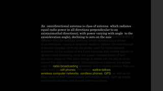
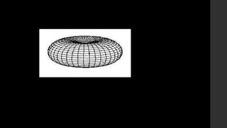
12.
An omnidirectional antennais class of antenna which radiates
equal radio power in all directions perpendicular to an
axis(azimuthal directions), with power varying with angle to the
axis(elevation angle), declining to zero on the axis Note that this is
different from an isotropic antenna, which radiates equal power
in all directions, having a spherical radiation pattern. Omnidirectional
antennas oriented vertically are widely used for nondirectional
antennas on the surface of the Earth because they radiate equally in
all horizontal directions, while the power radiated drops off with
elevation angle so little radio energy is aimed into the sky or down
toward the earth and wasted. Omnidirectional antennas are widely
used for radio broadcasting antennas, and in mobile devices that use
radio such as cell phones, FM radios, walkie-talkies,
wireless computer networks, cordless phones, GPS, as well as for
base stations that communicate with mobile radios, such as police
and taxi dispatchers and aircraft communications.
14.
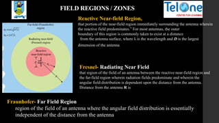
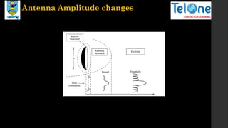
FIELD REGIONS /ZONES
Reactive Near-field Region,
that portion of the near-field region immediately surrounding the antenna wherein
the reactive field predominates.” For most antennas, the outer
boundary of this region is commonly taken to exist at a distance
from the antenna surface, where λ is the wavelength and D is the largest
dimension of the antenna
Fresnel- Radiating Near Field
that region of the field of an antenna between the reactive near-field region and
the far-field region wherein radiation fields predominate and wherein the
angular field distribution is dependent upon the distance from the antenna.
Distance from the antenna R is
Fraunhofer- Far Field Region
region of the field of an antenna where the angular field distribution is essentially
independent of the distance from the antenna
Antenna fundamentals contn’d
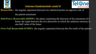
Beamwidth- the angular separation between two identical points on opposite side of
the pattern maximum
Half-Power Beamwidth (HPBW)- the plane containing the direction of the maximum of a
beam, the angle between the two directions in which the radiation intensity is
one-half value of the beam.
First-Null Beamwidth (FNBW)- the angular separation between the first nulls of the pattern
17.
Antenna fundamentals contn’d
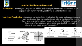
Bandwidth- the range of frequencies within which the performance of the antenna, with
respect to some characteristic, conforms to a specified standard
Antenna Polarization- Polarization of a radiated wave is defined as “that property of an electromagnetic
wave describing the time-varying direction and relative magnitude of the electric-
field vector; specifically, the figure traced as a function of time by the extremity of
the vector at a fixed location in space, and the sense in which it is traced, as
observed along the direction of propagation.”
18.
Antenna fundamentals contn’d
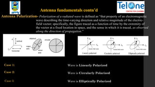
AntennaPolarization- Polarization of a radiated wave is defined as “that property of an electromagnetic
wave describing the time-varying direction and relative magnitude of the electric-
field vector; specifically, the figure traced as a function of time by the extremity of
the vector at a fixed location in space, and the sense in which it is traced, as observed
along the direction of propagation.”
𝑬=𝒂𝜽 𝑬𝜽 𝒄𝒐𝒔𝝎𝒕+𝒂𝝓 𝑬𝝓 𝒄𝒐𝒔(𝝎𝒕+𝜶)
Case 1: Wave is Linearly Polarized
Case 2:
Case 3:
Wave is Circularly Polarized
Wave is Elliptically Polarized
19.
• The polarizationof an antenna is loosely defined as the direction of the
electromagnetic fields produced by the antenna as energy radiates away
from it. These directional fields determine the direction in which the energy
moves away from or is received by an antenna
• It is defined as the orientation of the electric field vector of the radiated
electromagnetic wave by the antenna with a negligible amount of losses.
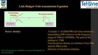
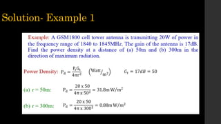
Link Budget- Friistransmission Equation
Power density Example 1- A GSM1800 cell tower antenna is
transmitting 20W of power in the frequency
range of 1840 to 1845MHz. The gain of the
antenna is 17dB.
Find the power density at a distance of (a) 50m
and (b) 300m in the
direction of maximum radiation.
Friis formula is valid for a received signal in
the far field
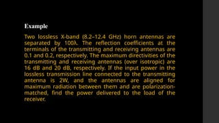
Example
Two lossless X-band(8.2–12.4 GHz) horn antennas are
separated by 100λ. The reflection coefficients at the
terminals of the transmitting and receiving antennas are
0.1 and 0.2, respectively. The maximum directivities of the
transmitting and receiving antennas (over isotropic) are
16 dB and 20 dB, respectively. If the input power in the
lossless transmission line connected to the transmitting
antenna is 2W, and the antennas are aligned for
maximum radiation between them and are polarization-
matched, find the power delivered to the load of the
receiver.
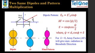
Antenna Arrays
Arrays ofTwo Isotropic Sources
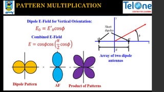
Principles of Pattern Multiplication
Linear Array of N Elements with Uniform Amplitude
Broadside
Ordinary Endfire