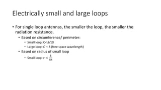
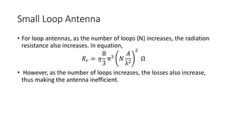
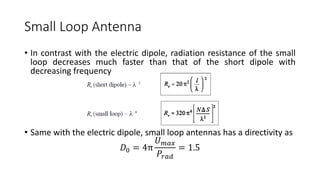
LOOP ANTENNAS
Frank Paul F. Abilay
Outline
• Loop Antenna
• Electrically small and large loop antennas
• Small loop antenna
• Constant and non constant current loop antennas
• Equivalent Circuit of Loop Antennas
• Ferrite Loop
Loop antenna
• An antenna constructed in a form of a loop
• Loops may vary in shape: square, circular, elliptical
• Can be classified as electrically small or electrically large
• Based on circumference/ perimeter:
• Small loop: C< λ/10
• Large loop: C ∼ λ (free space wavelength)
• Common band of application
• HF (3–30 MHz)
• VHF (30–300 MHz)
• UHF (300–3,000 MHz)
• Microwave bands
Loop antenna
• Are inductive in nature
Electrically small and large loops
• For single loop antennas, the smaller the loop, the smaller the
radiation resistance.
• Based on circumference/ perimeter:
• Small loop: C< λ/10
• Large loop: C ∼ λ (free space wavelength)
• Based on radius of small loop
• Small loop: r <
λ
6π
Small Loop Antenna
• The small loops, regardless of their shape, have a far-field pattern very
similar to that of a small electric dipole
• Has a electrical circumference of C< λ/10
• Has an equivalent radiation pattern with electric dipoles
RADIATION PARAMETERS
• Power pattern
𝐹(θ) = 𝑠𝑖𝑛2
θ
• Radiation Resistance for single loop antenna
𝑅 𝑟 = η
8
3
π3
𝐴
λ2
2
Ω
Small Loop Antenna
• For loop antennas, as the number of loops (N) increases, the radiation
resistance also increases. In equation,
𝑅 𝑟 = η
8
3
π3 𝑁
𝐴
λ2
2
Ω
• However, as the number of loops increases, the losses also increase,
thus making the antenna inefficient.
Small Loop Antenna
• In contrast with the electric dipole, radiation resistance of the small
loop decreases much faster than that of the short dipole with
decreasing frequency
• Same with the electric dipole, small loop antennas has a directivity as
𝐷0 = 4π
𝑈 𝑚𝑎𝑥
𝑃𝑟𝑎𝑑
= 1.5
Small Loop Antenna
Circular Loops of Constant Current
• For analysis of circular loops with radius a, and with constant current,
only far fields will be considered.
Circular Loops of Constant Current
• Equations are only valid for loops of thin wires
• Far fields are approximated as:
• Using the Bessel function, far fields can be expressed as:
Constant Current Loop
• For circular loops with
constant currents, as the
radius of the loop increases,
the directivity decreases.
Non constant Current loops
• When wire diameters
increase, the
constant current
approximation does
not apply. Variation in
the radiation
parameters occur.
Input impedance
changes.
Non constant Current loops
• When wire diameters
increase, the
constant current
approximation does
not apply. Variation in
the radiation
parameters occur.
Input impedance
changes.
Equivalent circuit
Loss Resistance
• Caused by high frequencies and proximity effect
• High frequency loss:
• Proximity Loss occurs when two wires are close to each other causing
the skin effect, wherein the fields on the nearby wires interferes and
cancels each other in some extent
Loss resistance
Two wire in cross section view,
showing the proximity effect
Ferrite Loops
• A ferrite loop is formed when a ferrite core is inserted on the loop of the
antenna
• The radiation resistance and radiation efficiency increases with the
insertion of a ferrite core
• High magnetic permeability in the operating frequency band, which
increases magnetic flux, thus increasing induced voltage
• The increase in the magnetic flux, represented as the effective relative
permeability, increases radiation resistance by:
• d

Loop Antennas

  • 1.
  • 2.
    Outline • Loop Antenna •Electrically small and large loop antennas • Small loop antenna • Constant and non constant current loop antennas • Equivalent Circuit of Loop Antennas • Ferrite Loop
  • 3.
    Loop antenna • Anantenna constructed in a form of a loop • Loops may vary in shape: square, circular, elliptical • Can be classified as electrically small or electrically large • Based on circumference/ perimeter: • Small loop: C< λ/10 • Large loop: C ∼ λ (free space wavelength) • Common band of application • HF (3–30 MHz) • VHF (30–300 MHz) • UHF (300–3,000 MHz) • Microwave bands
  • 4.
    Loop antenna • Areinductive in nature
  • 5.
    Electrically small andlarge loops • For single loop antennas, the smaller the loop, the smaller the radiation resistance. • Based on circumference/ perimeter: • Small loop: C< λ/10 • Large loop: C ∼ λ (free space wavelength) • Based on radius of small loop • Small loop: r < λ 6π
  • 6.
    Small Loop Antenna •The small loops, regardless of their shape, have a far-field pattern very similar to that of a small electric dipole • Has a electrical circumference of C< λ/10 • Has an equivalent radiation pattern with electric dipoles RADIATION PARAMETERS • Power pattern 𝐹(θ) = 𝑠𝑖𝑛2 θ • Radiation Resistance for single loop antenna 𝑅 𝑟 = η 8 3 π3 𝐴 λ2 2 Ω
  • 7.
    Small Loop Antenna •For loop antennas, as the number of loops (N) increases, the radiation resistance also increases. In equation, 𝑅 𝑟 = η 8 3 π3 𝑁 𝐴 λ2 2 Ω • However, as the number of loops increases, the losses also increase, thus making the antenna inefficient.
  • 8.
    Small Loop Antenna •In contrast with the electric dipole, radiation resistance of the small loop decreases much faster than that of the short dipole with decreasing frequency • Same with the electric dipole, small loop antennas has a directivity as 𝐷0 = 4π 𝑈 𝑚𝑎𝑥 𝑃𝑟𝑎𝑑 = 1.5
  • 9.
  • 10.
    Circular Loops ofConstant Current • For analysis of circular loops with radius a, and with constant current, only far fields will be considered.
  • 11.
    Circular Loops ofConstant Current • Equations are only valid for loops of thin wires • Far fields are approximated as: • Using the Bessel function, far fields can be expressed as:
  • 12.
    Constant Current Loop •For circular loops with constant currents, as the radius of the loop increases, the directivity decreases.
  • 13.
    Non constant Currentloops • When wire diameters increase, the constant current approximation does not apply. Variation in the radiation parameters occur. Input impedance changes.
  • 14.
    Non constant Currentloops • When wire diameters increase, the constant current approximation does not apply. Variation in the radiation parameters occur. Input impedance changes.
  • 15.
  • 16.
    Loss Resistance • Causedby high frequencies and proximity effect • High frequency loss: • Proximity Loss occurs when two wires are close to each other causing the skin effect, wherein the fields on the nearby wires interferes and cancels each other in some extent
  • 17.
    Loss resistance Two wirein cross section view, showing the proximity effect
  • 18.
    Ferrite Loops • Aferrite loop is formed when a ferrite core is inserted on the loop of the antenna • The radiation resistance and radiation efficiency increases with the insertion of a ferrite core • High magnetic permeability in the operating frequency band, which increases magnetic flux, thus increasing induced voltage • The increase in the magnetic flux, represented as the effective relative permeability, increases radiation resistance by: • d