Downloaded 120 times


![Dwell Time
The time that an antenna beam spends on a target is called dwell time TD.
The dwell time of a 2D–search radar depends predominantly on:
1) the antennas horizontally beam width AZ
2) the turn speed n of the antenna (rotations per minute).
The dwell time can be calculated using the following equation:
TD = (ΘAZ · 60)/(360° · n) ; in [seconds]](https://image.slidesharecdn.com/radarfundamentals-180508074808/85/Radar-fundamentals-21-320.jpg)
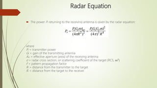
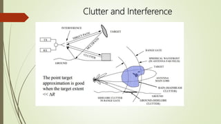
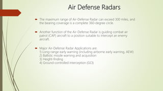


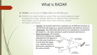
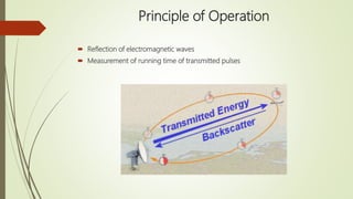
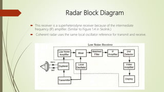
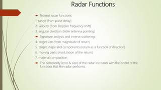
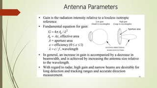
Radar is a system that detects objects using electromagnetic waves to determine their range, altitude, direction, and speed. It operates on principles of wave reflection and measurement of pulse timing, with various functions to analyze target characteristics and clutter. Different radar types are designed for specific applications such as air defense, air traffic control, and precision approaches in challenging conditions.