Downloaded 152 times
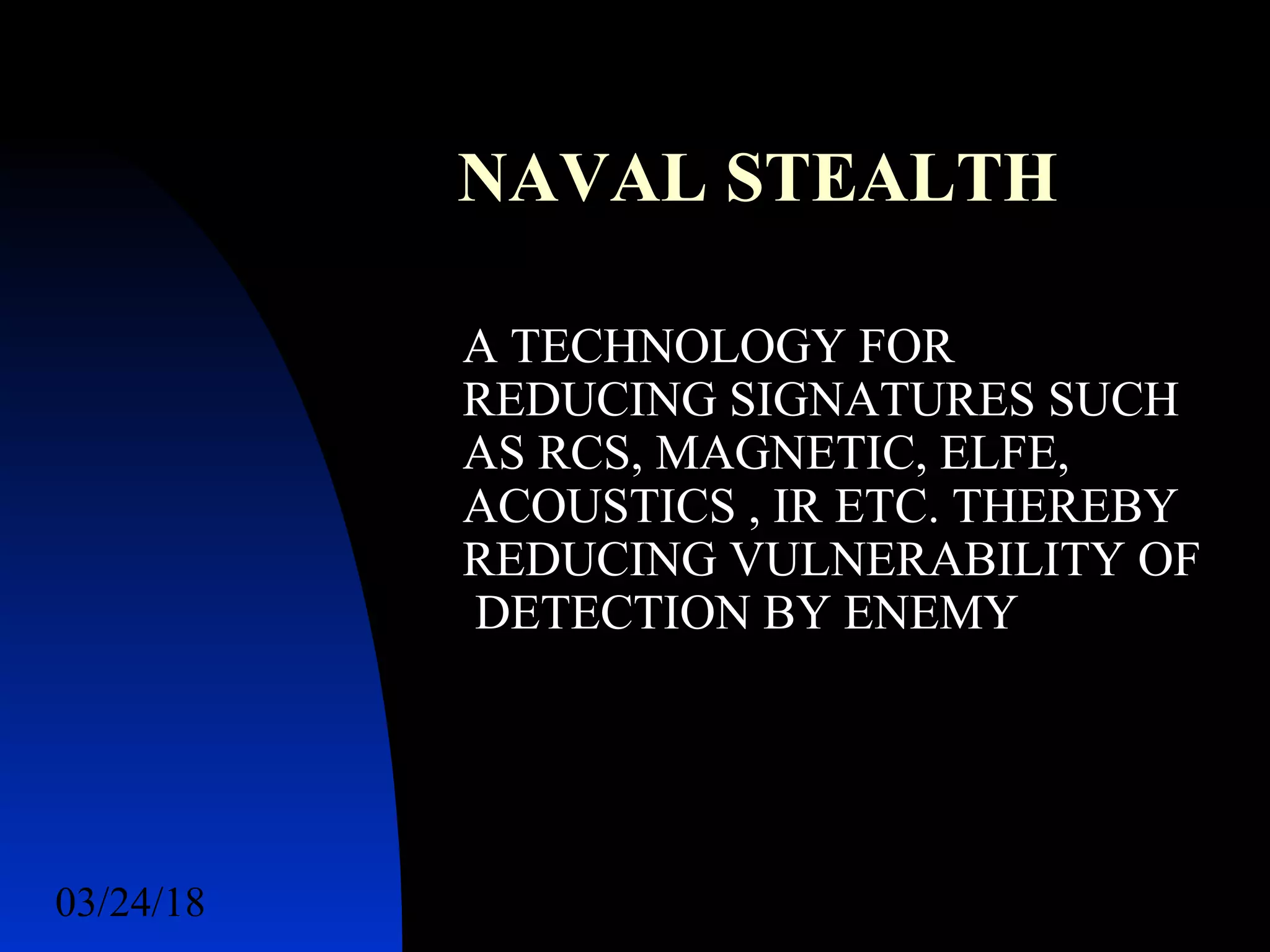
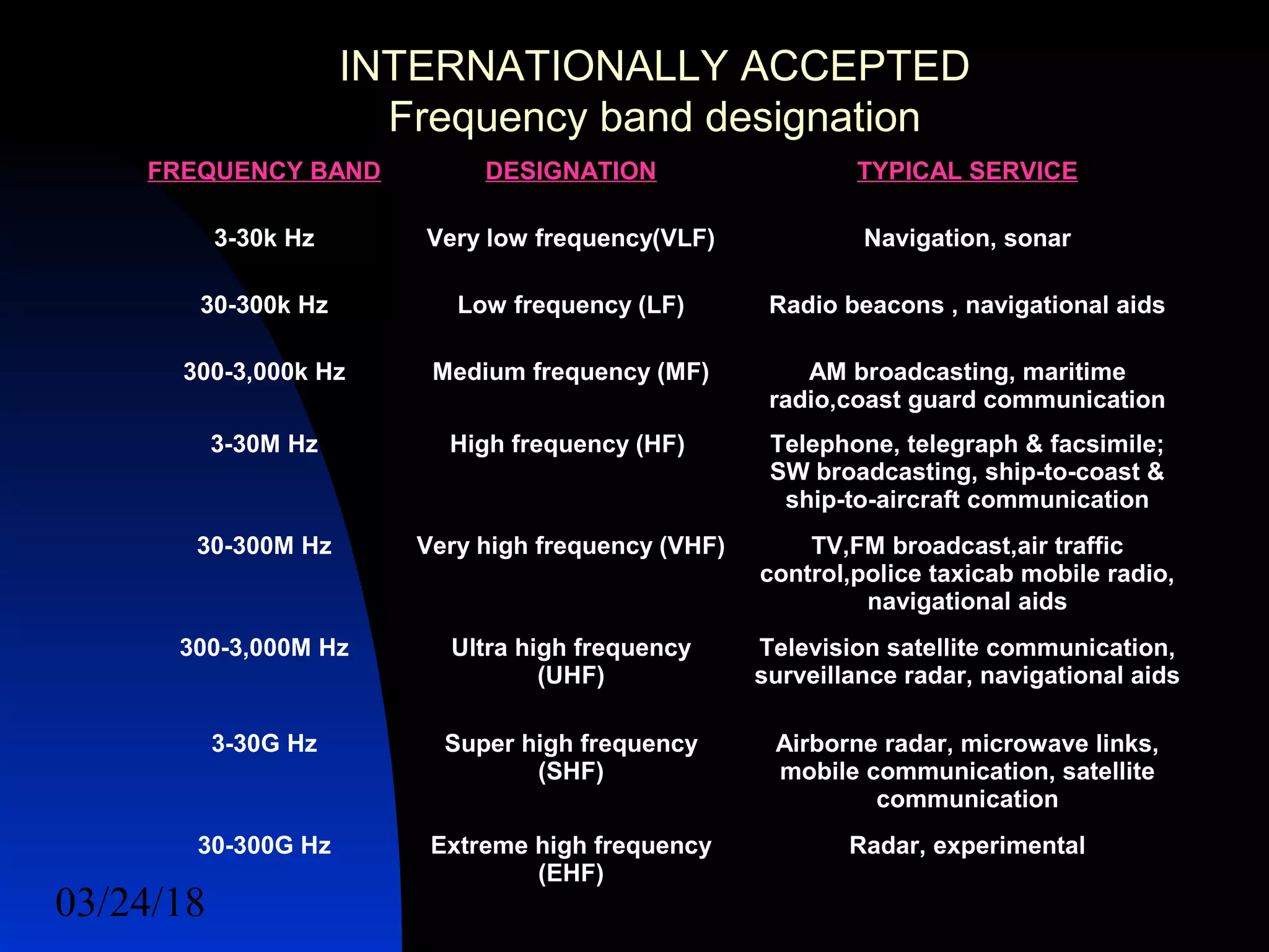
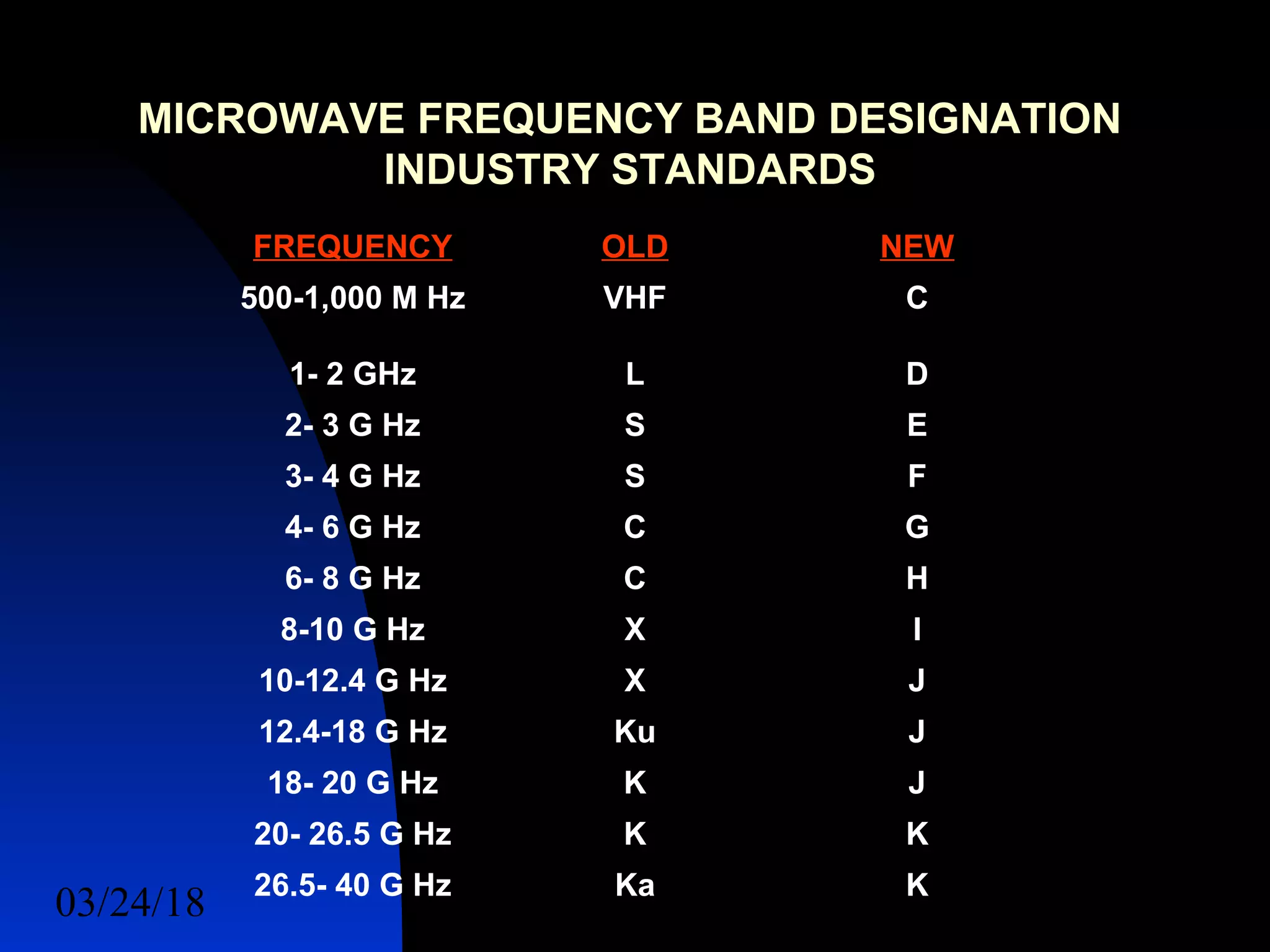
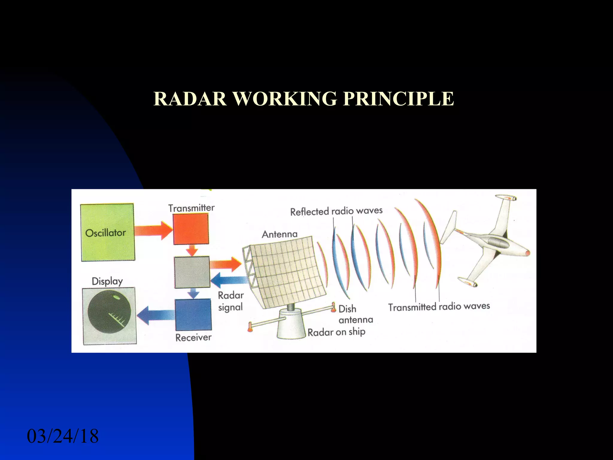
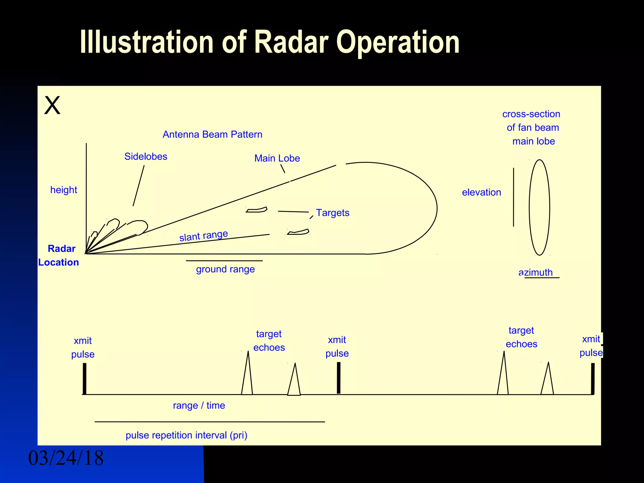
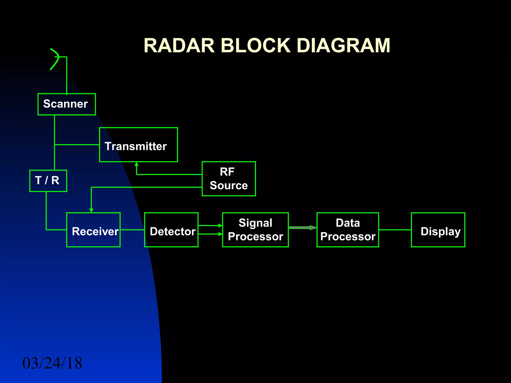
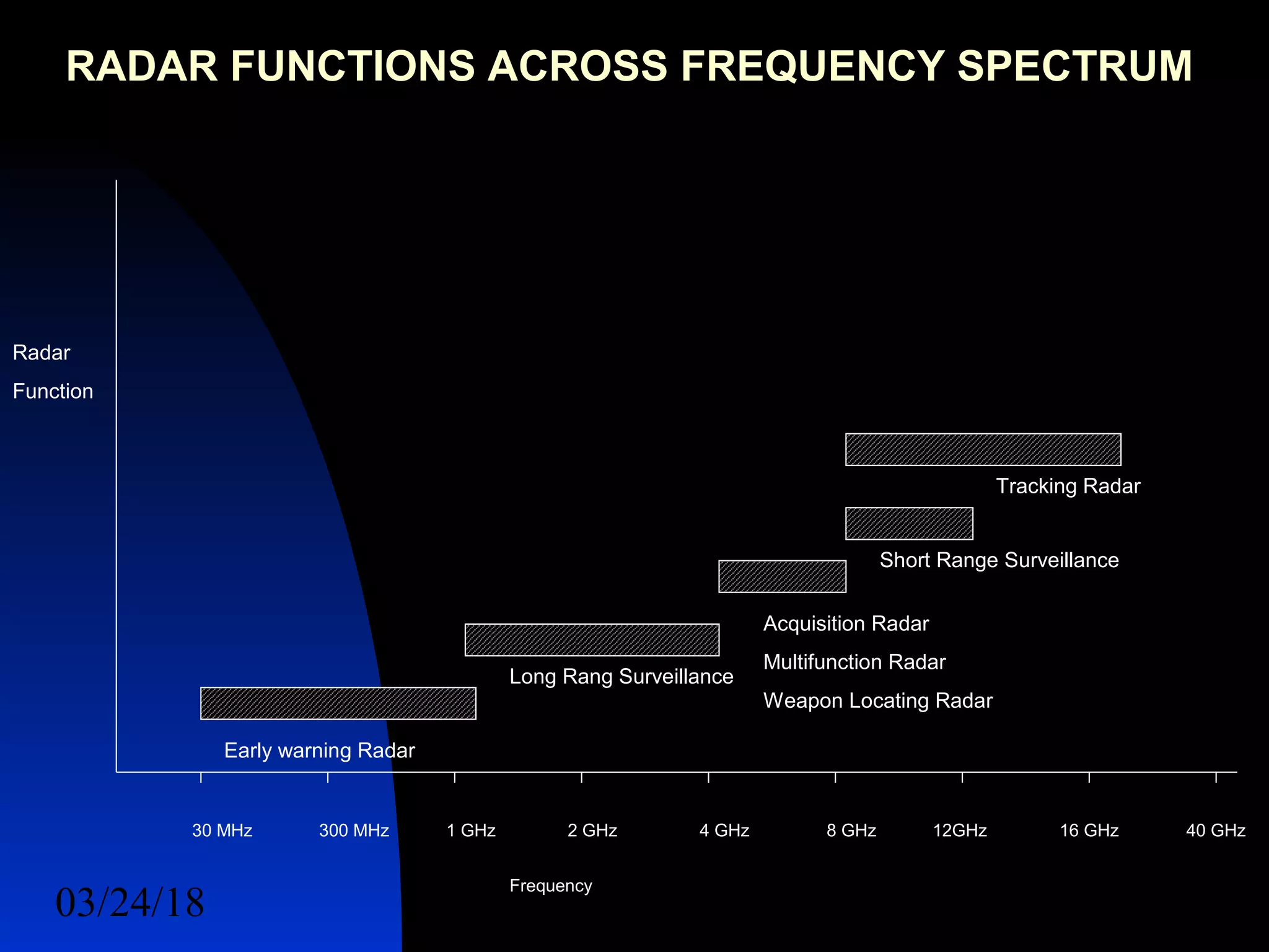
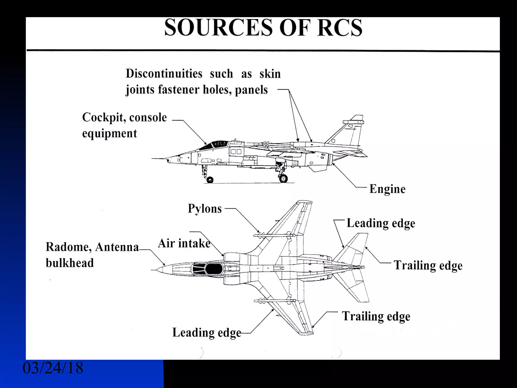
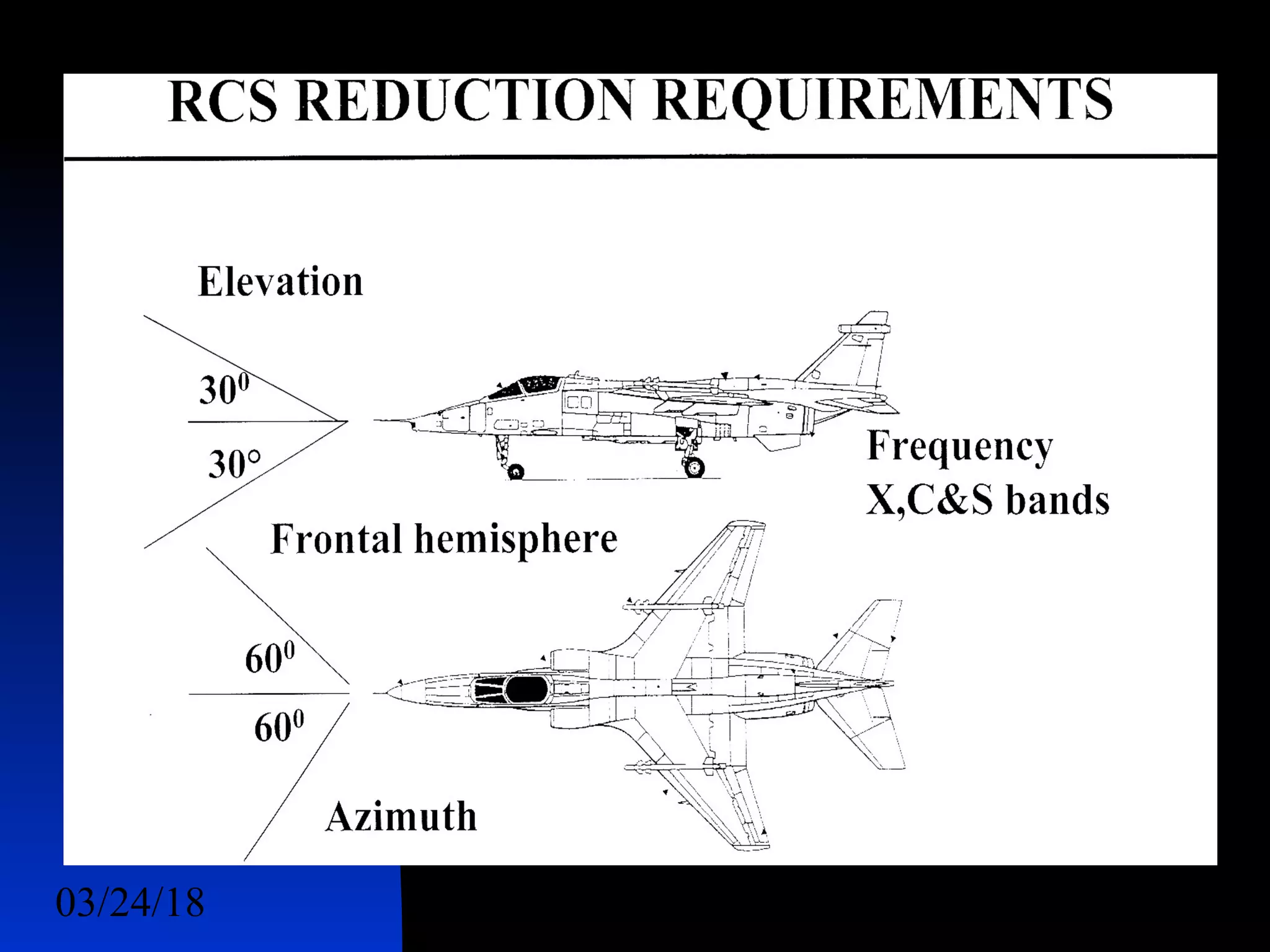

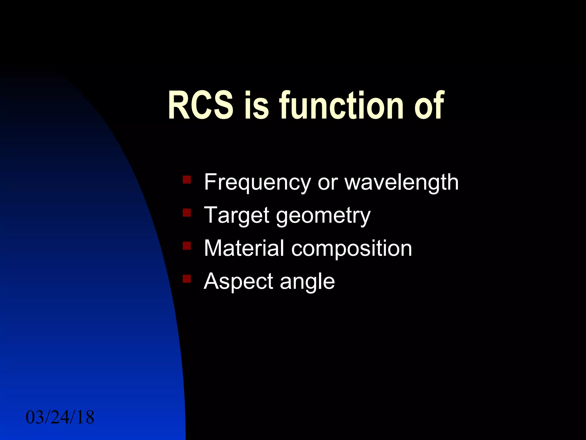

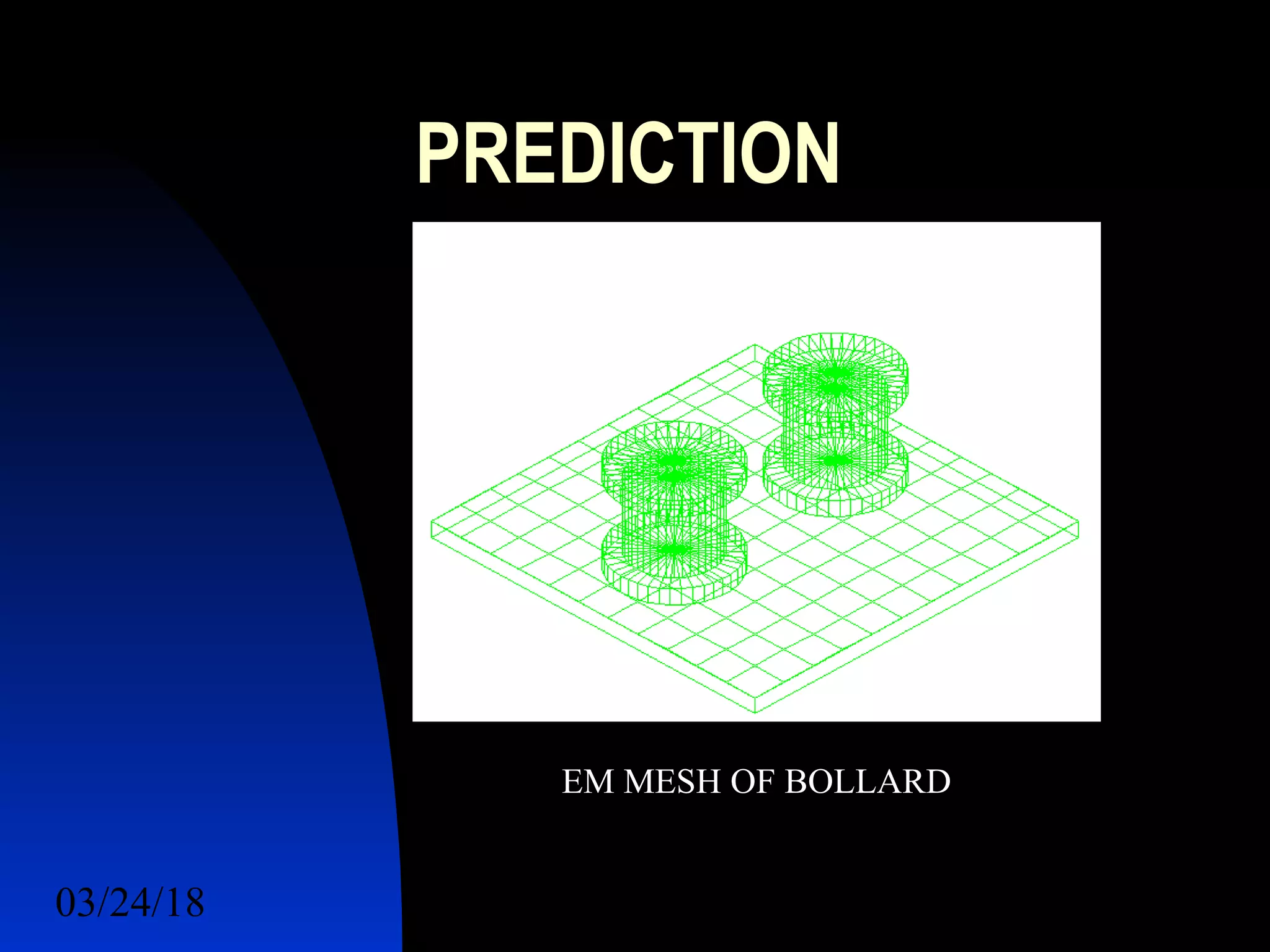
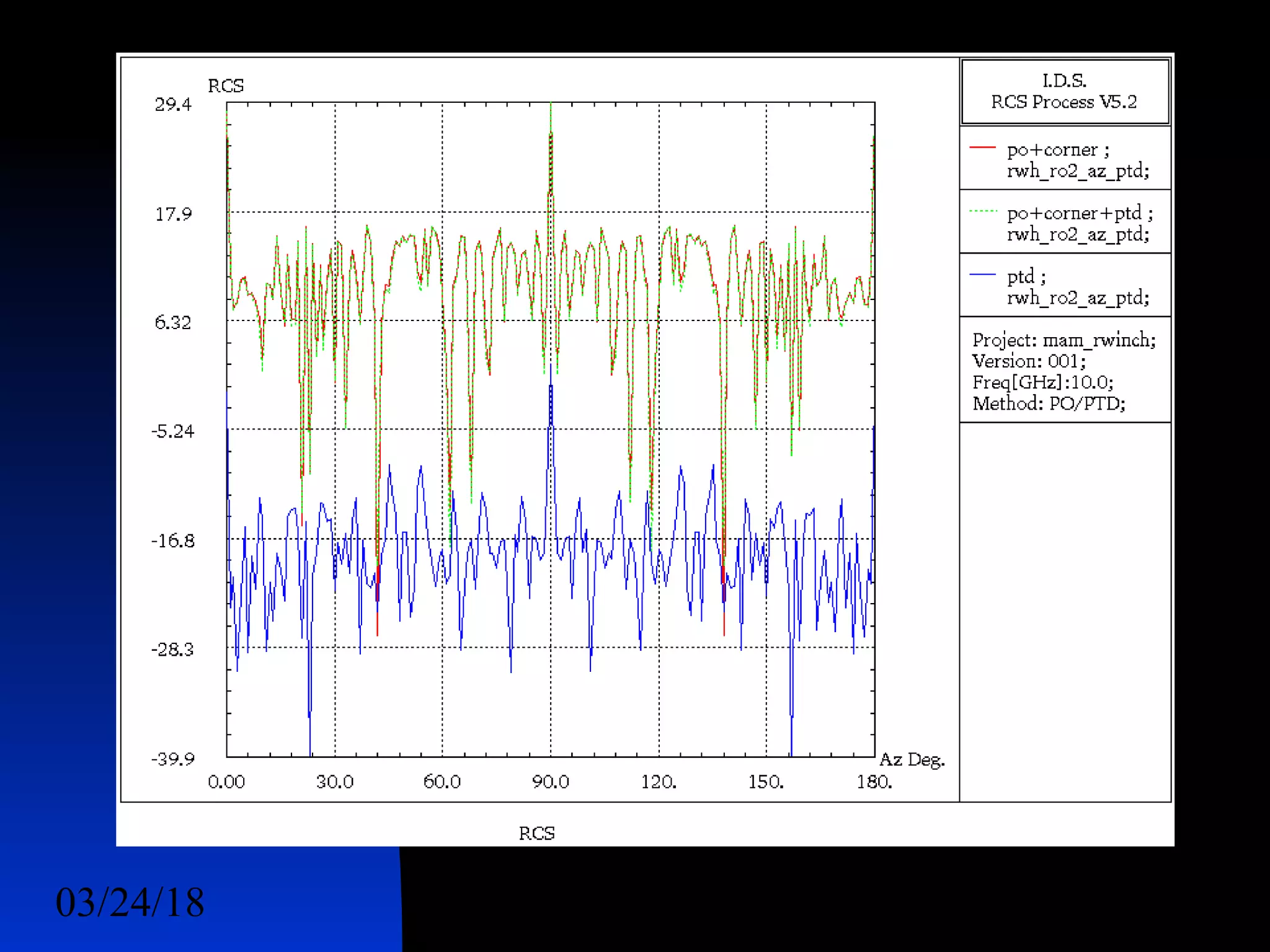
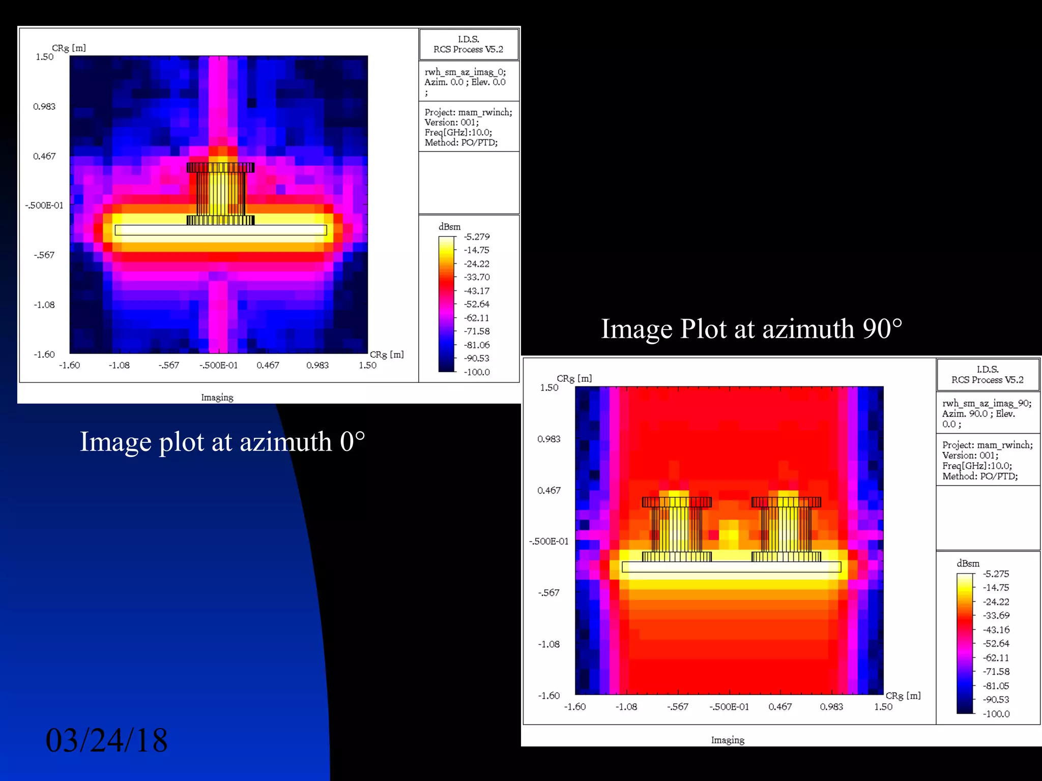
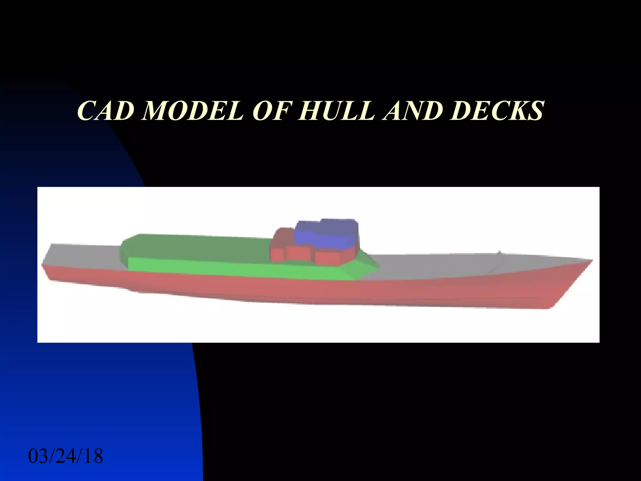
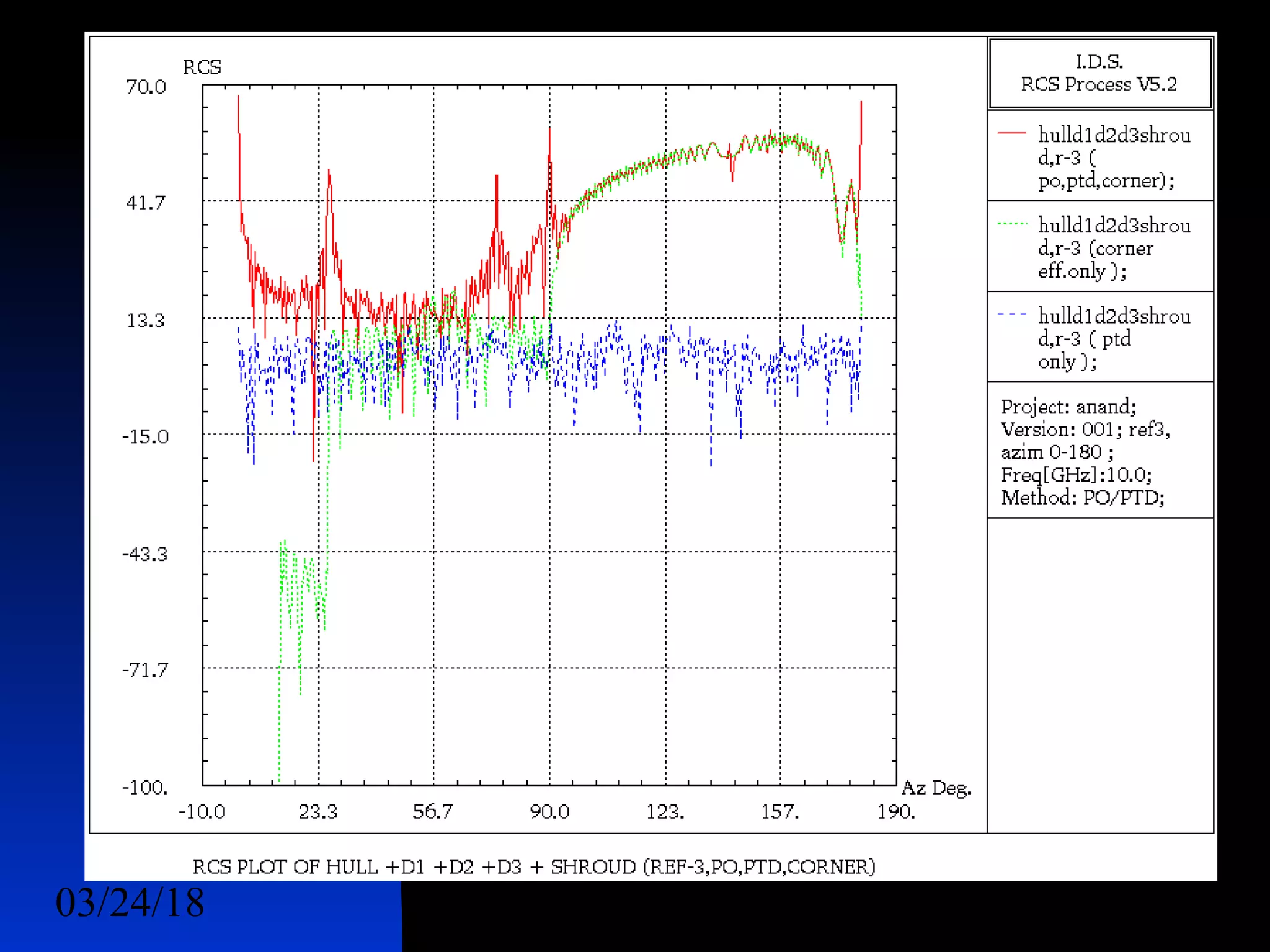
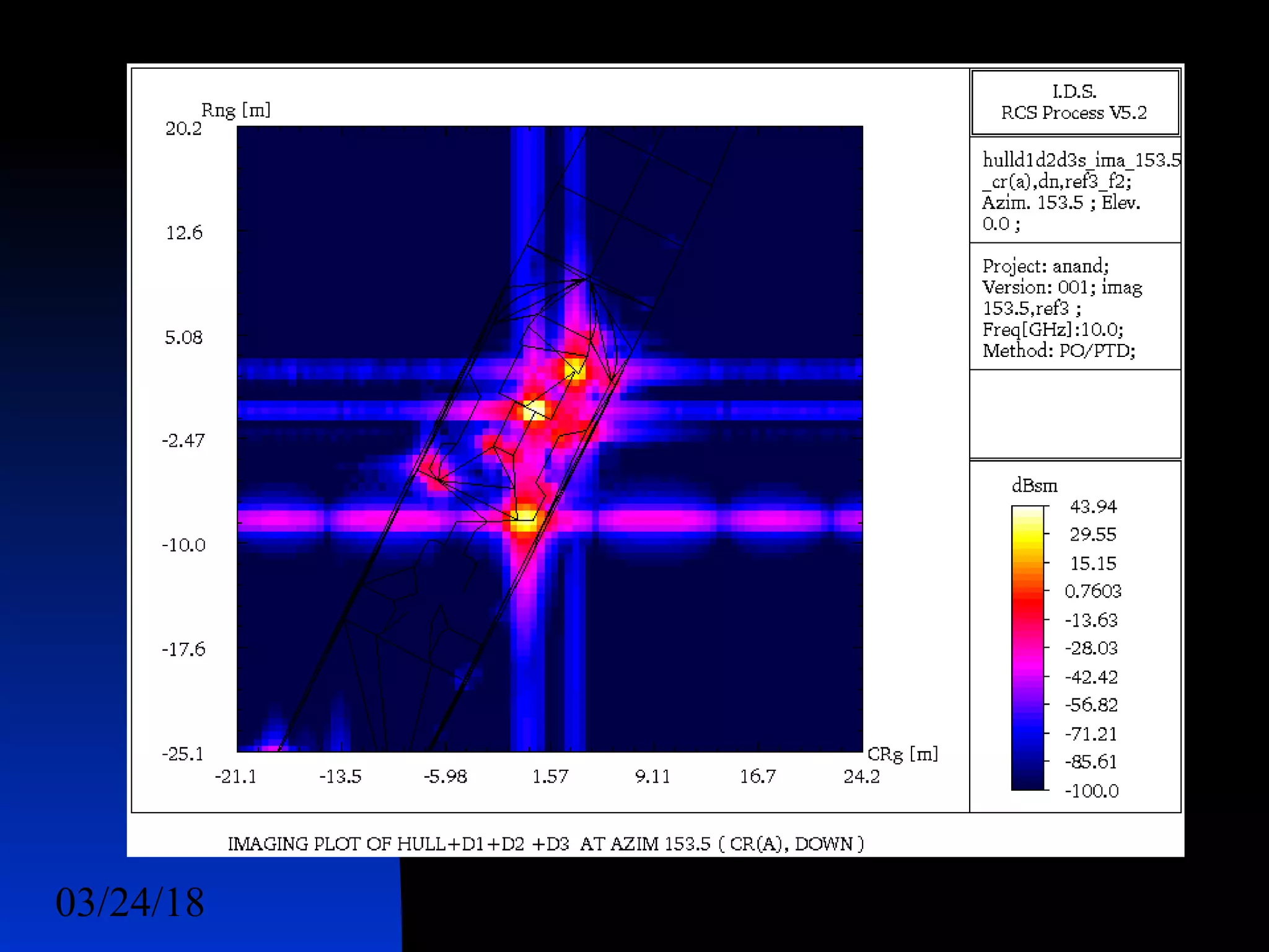
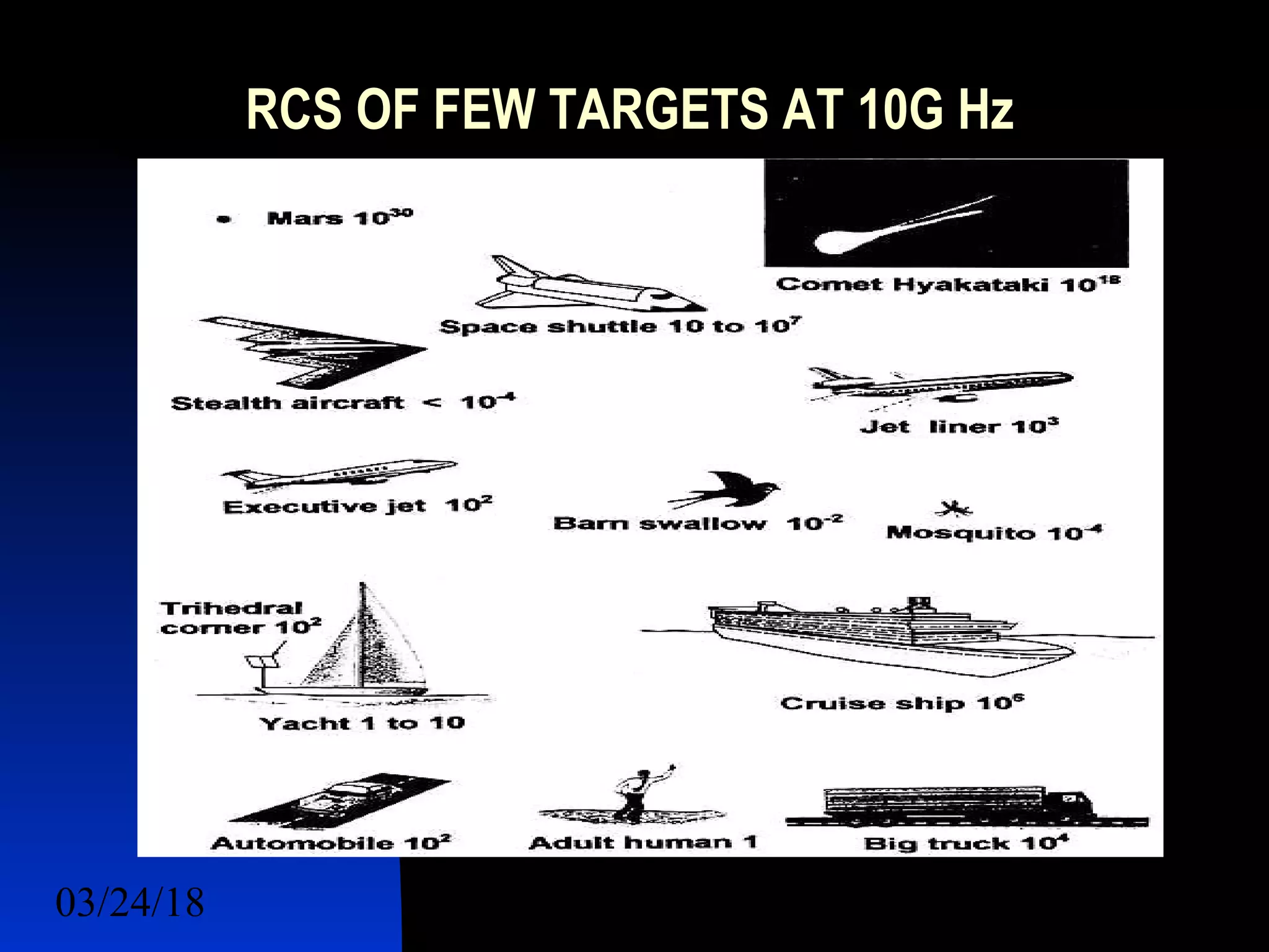
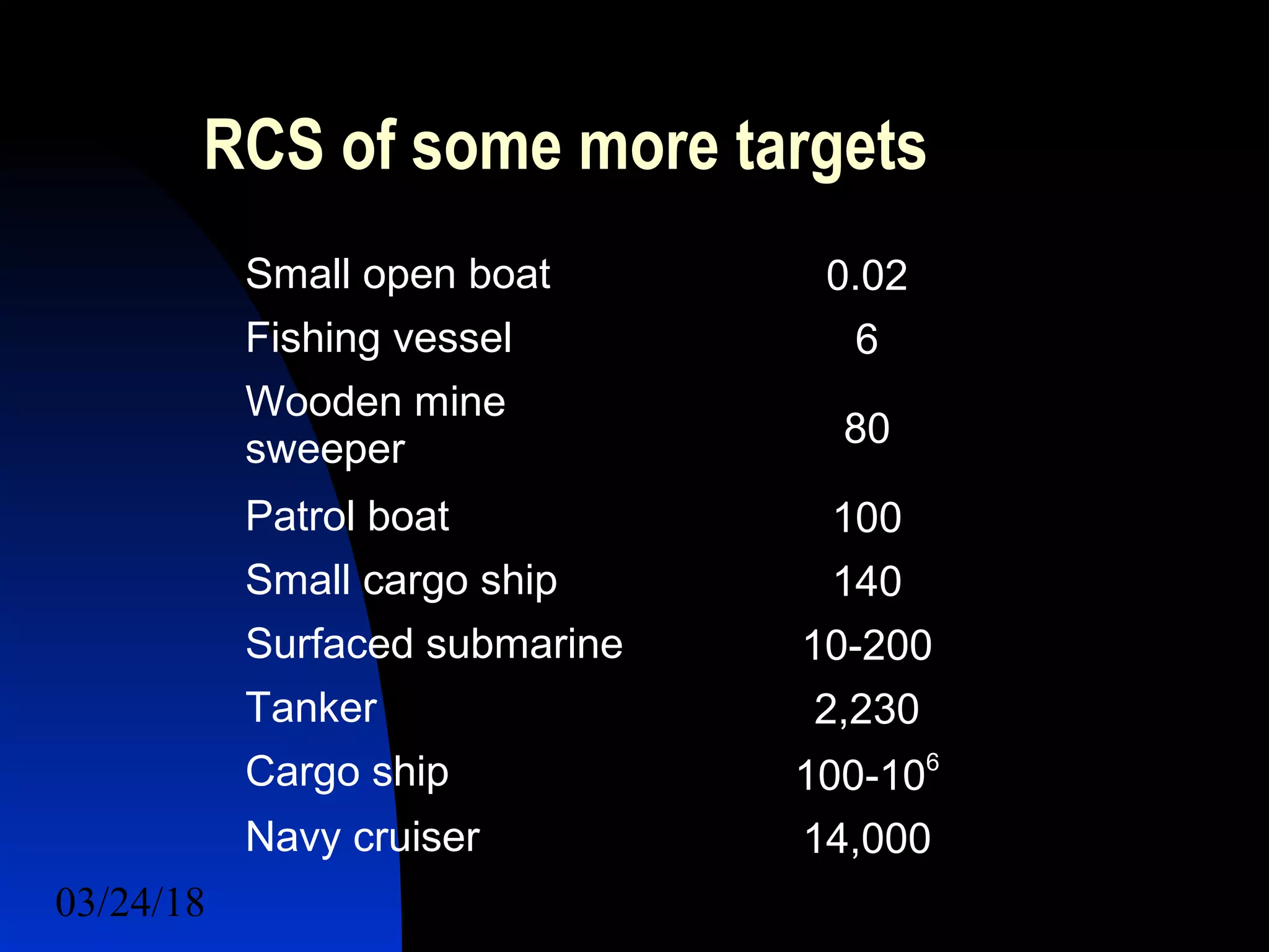
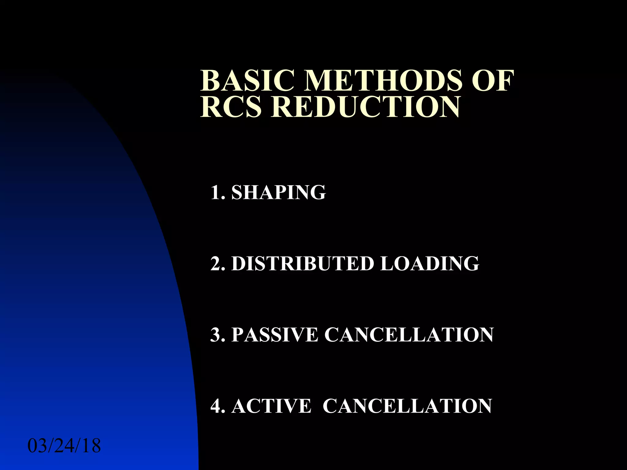
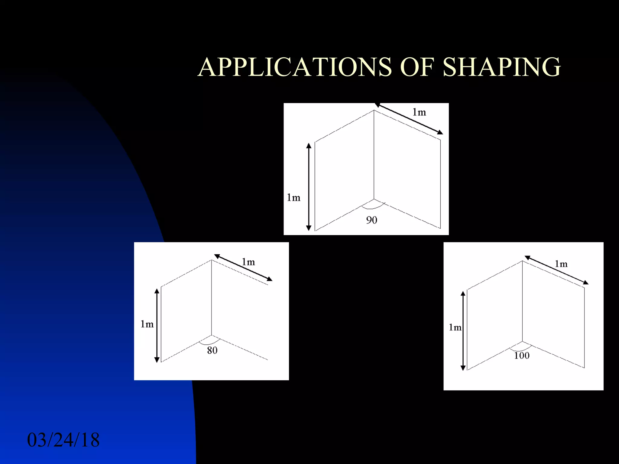
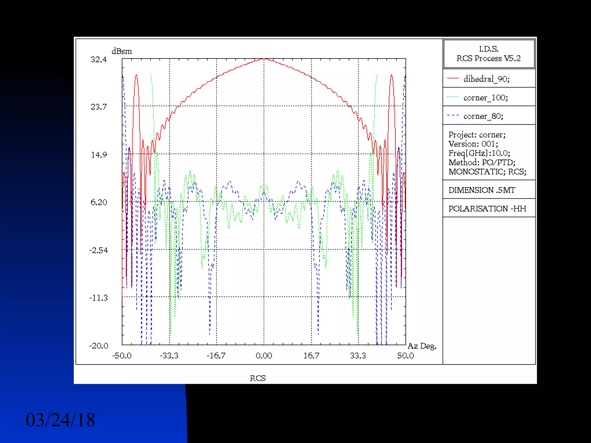
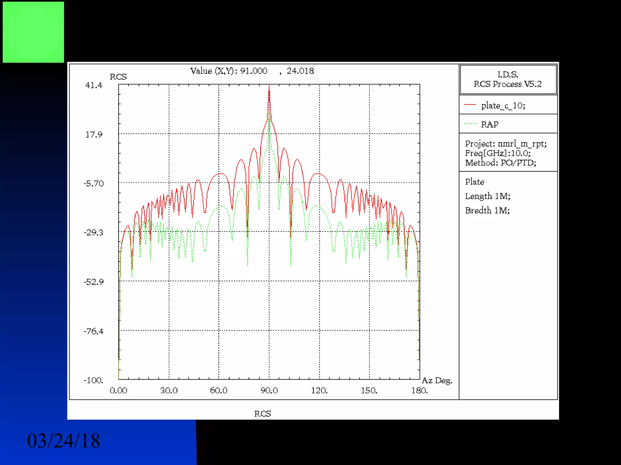
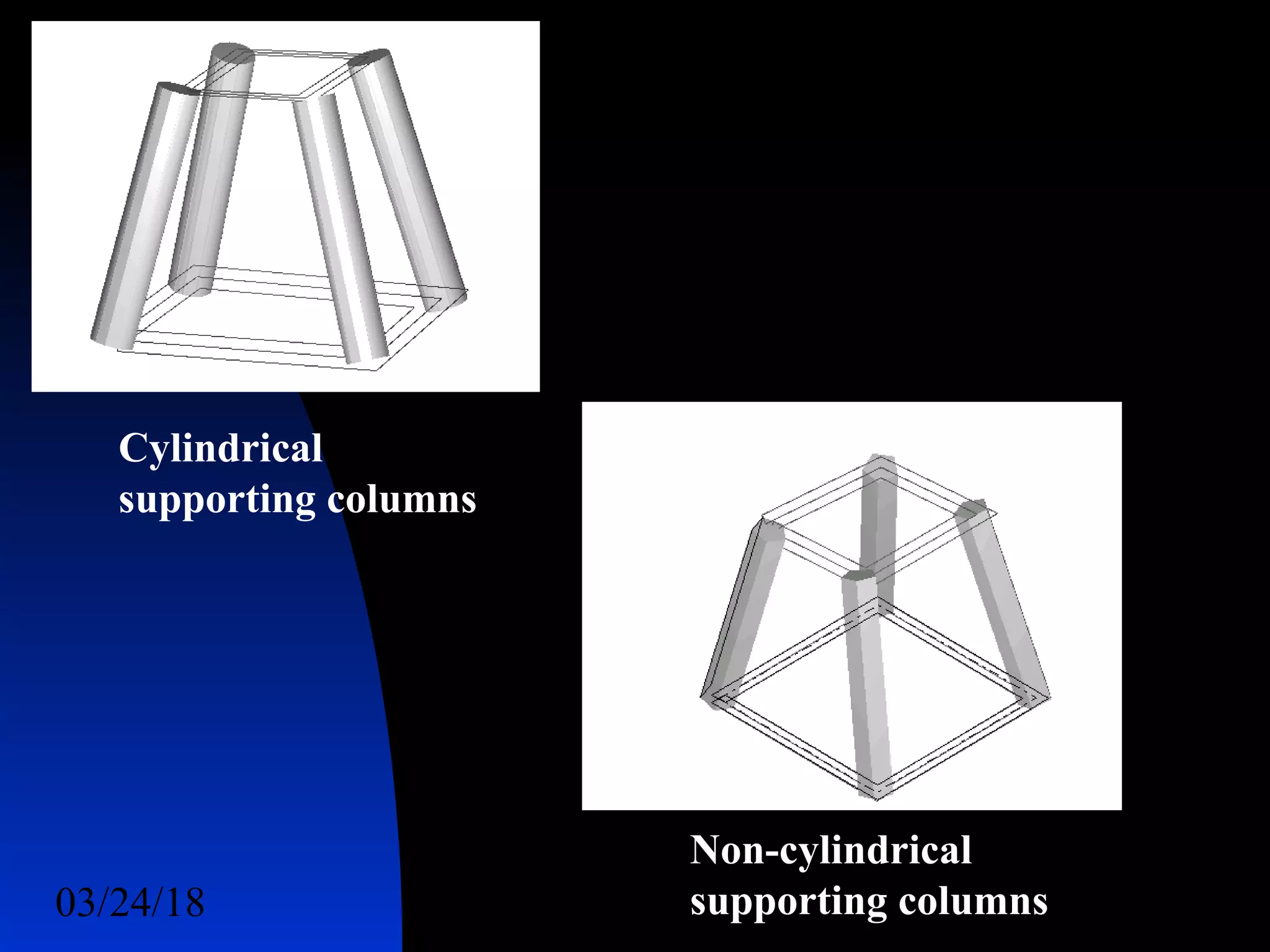
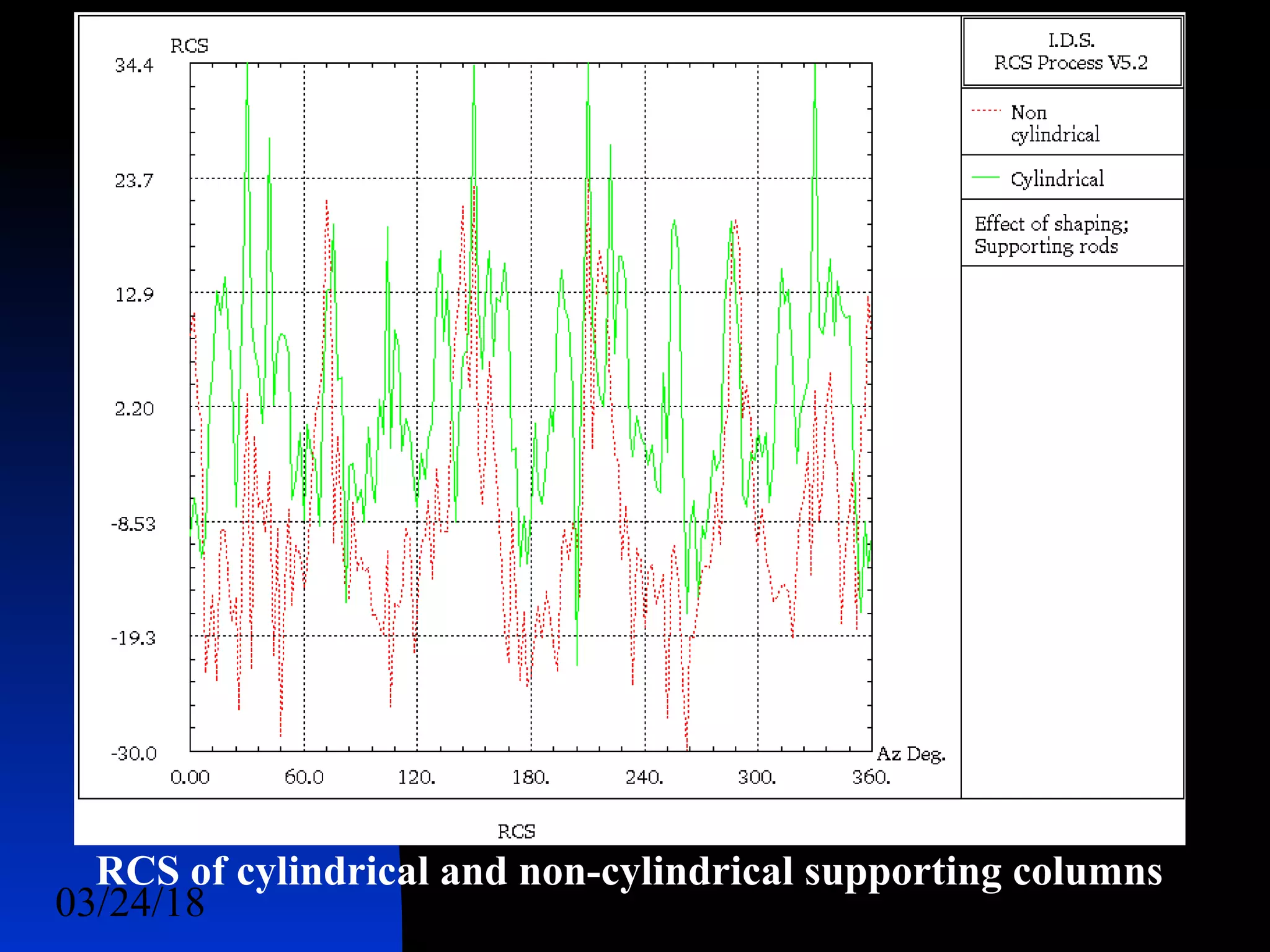
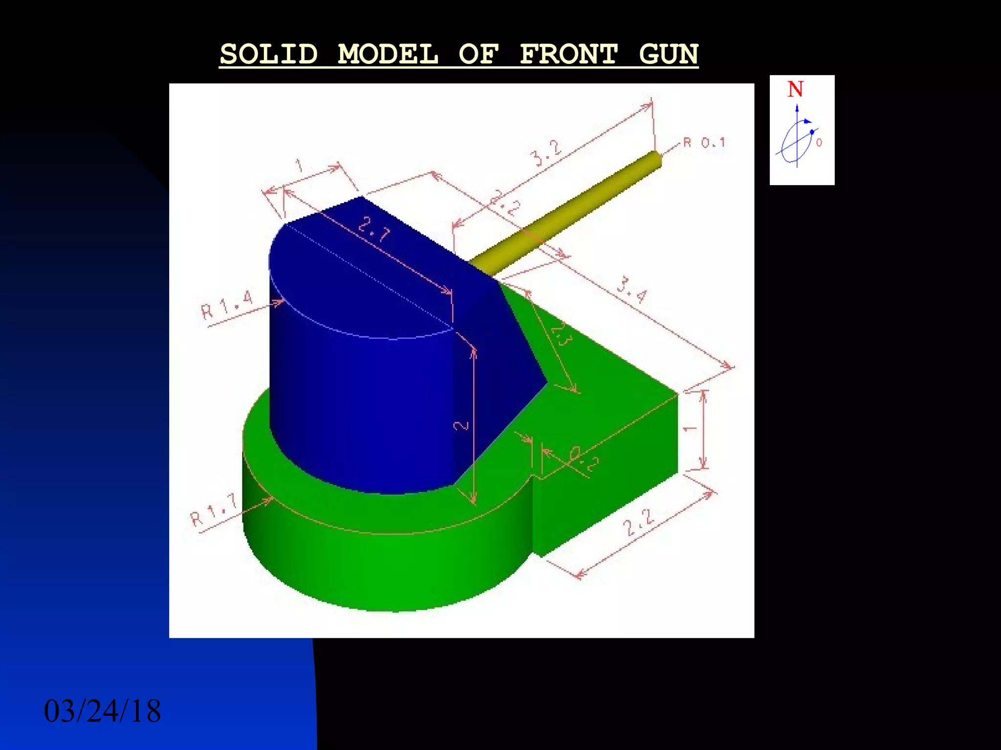
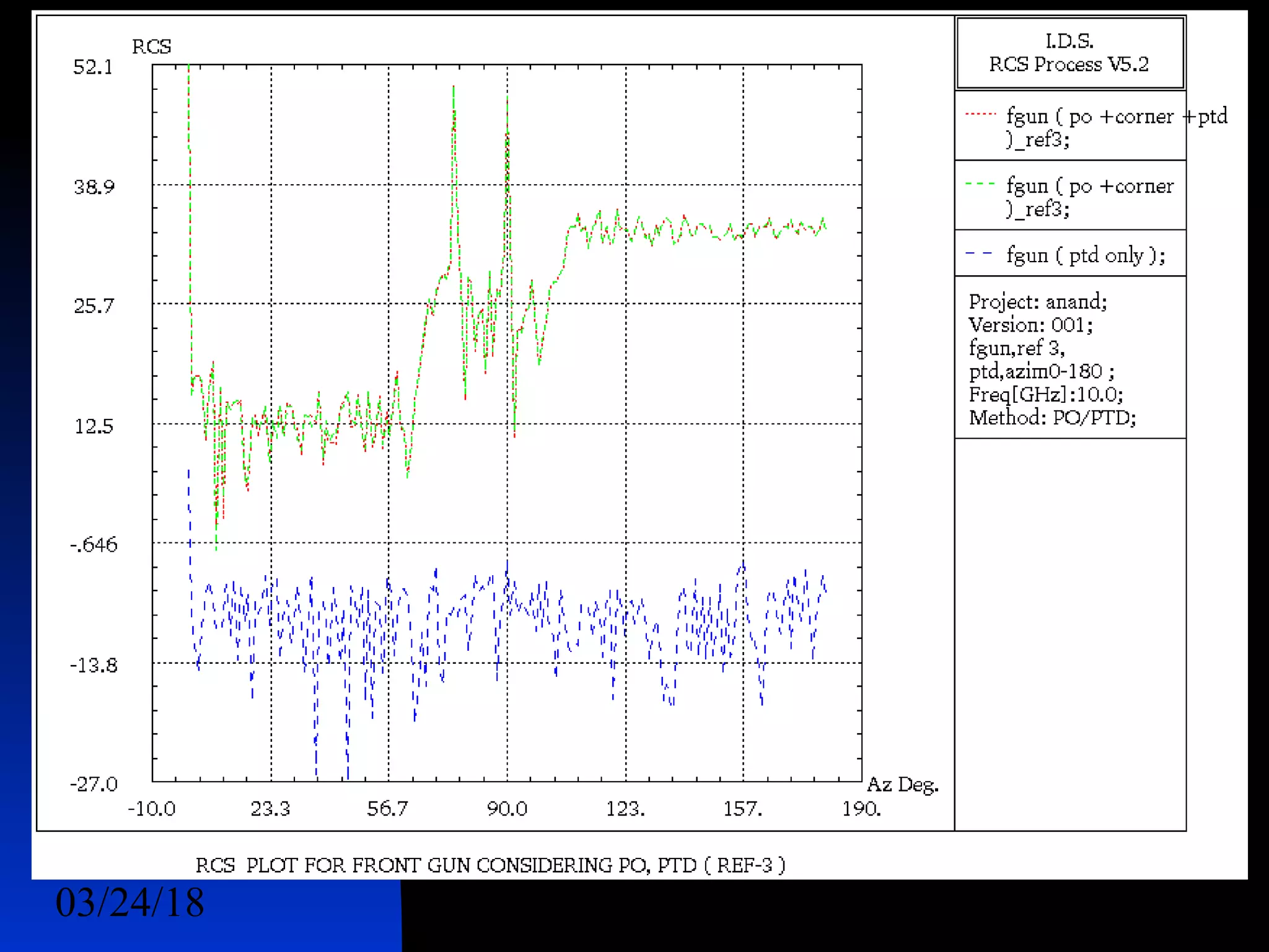
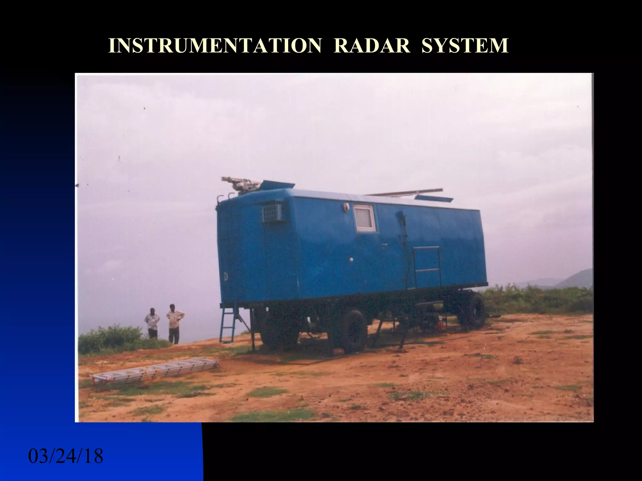
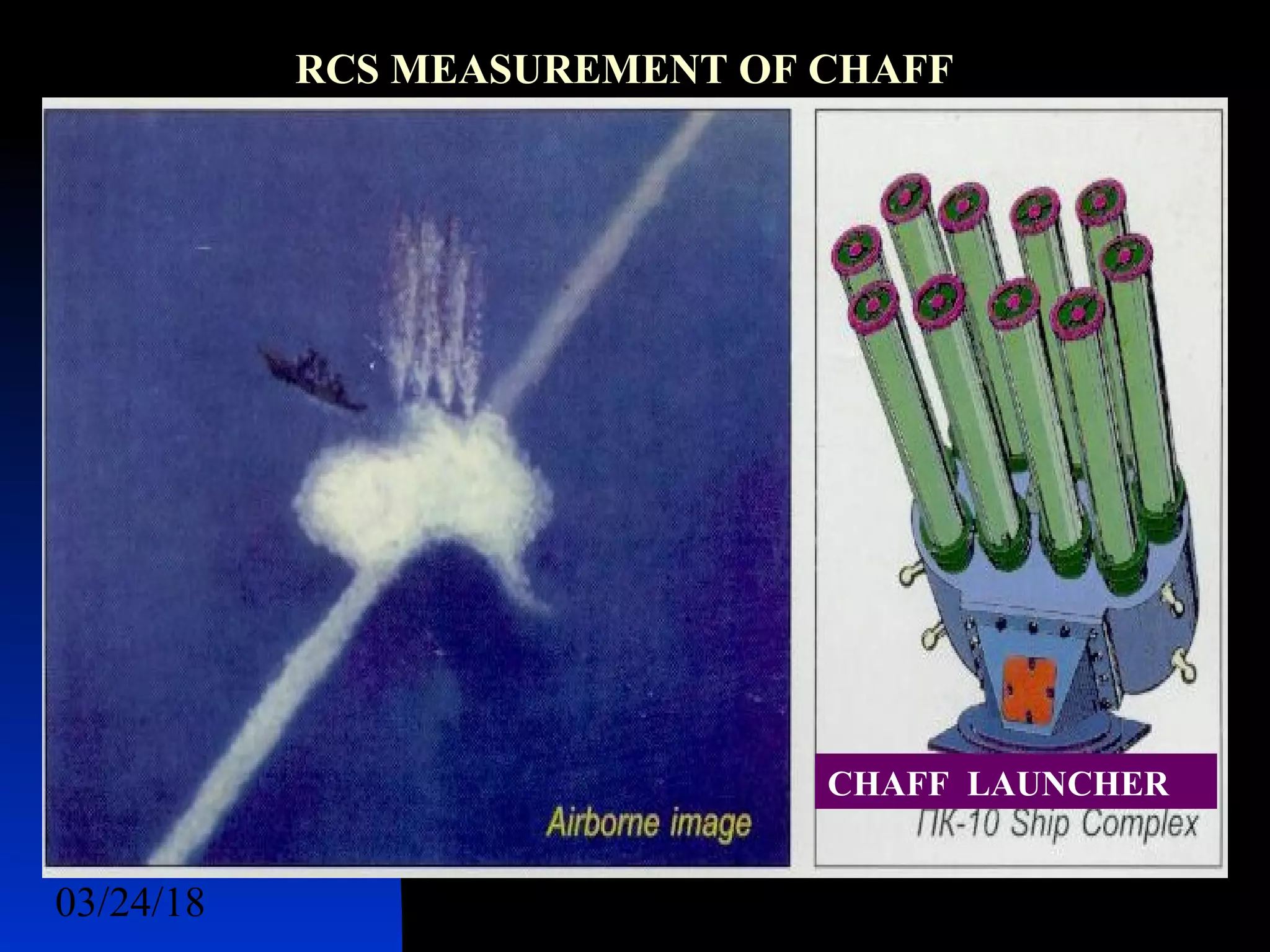
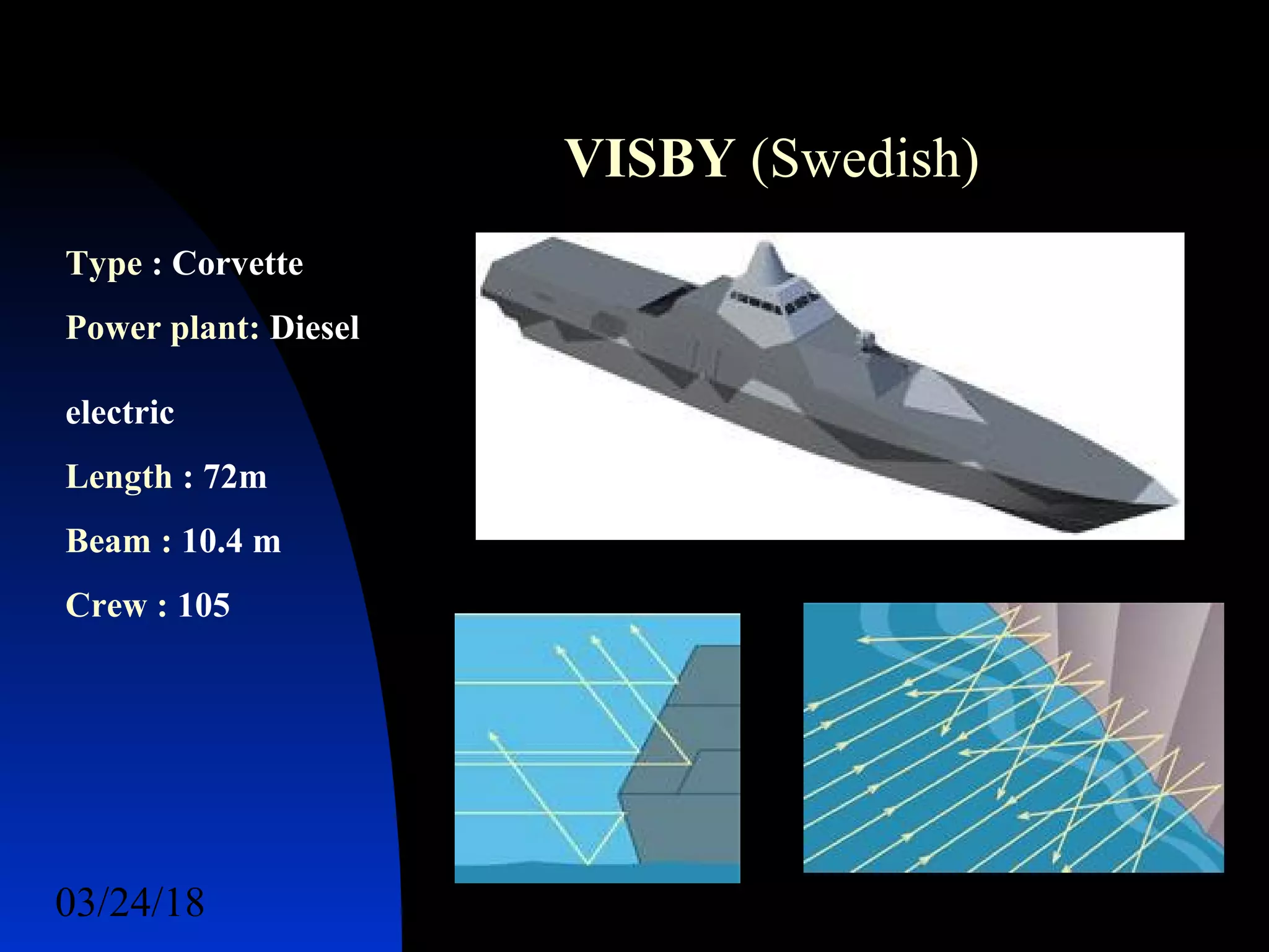
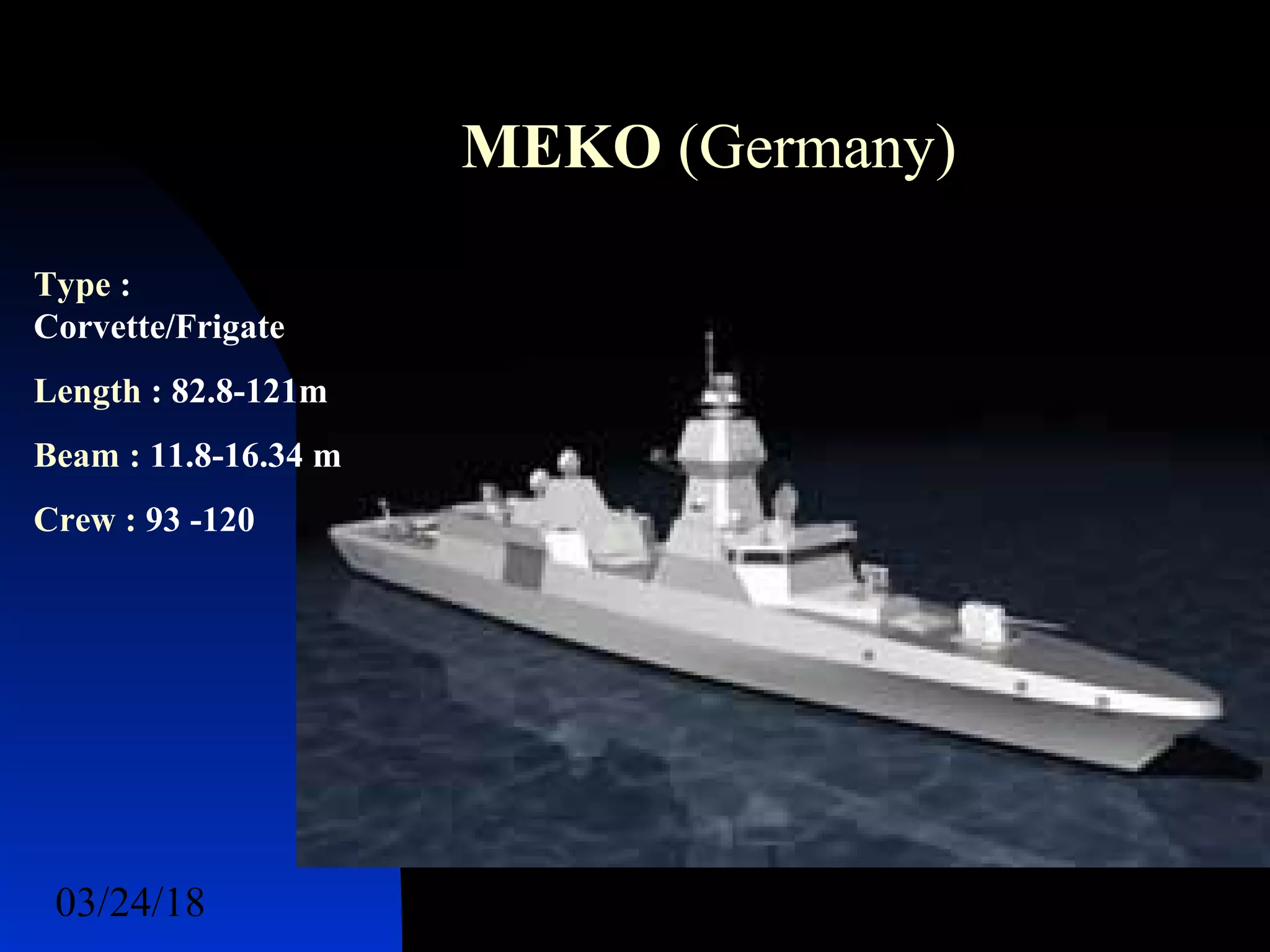
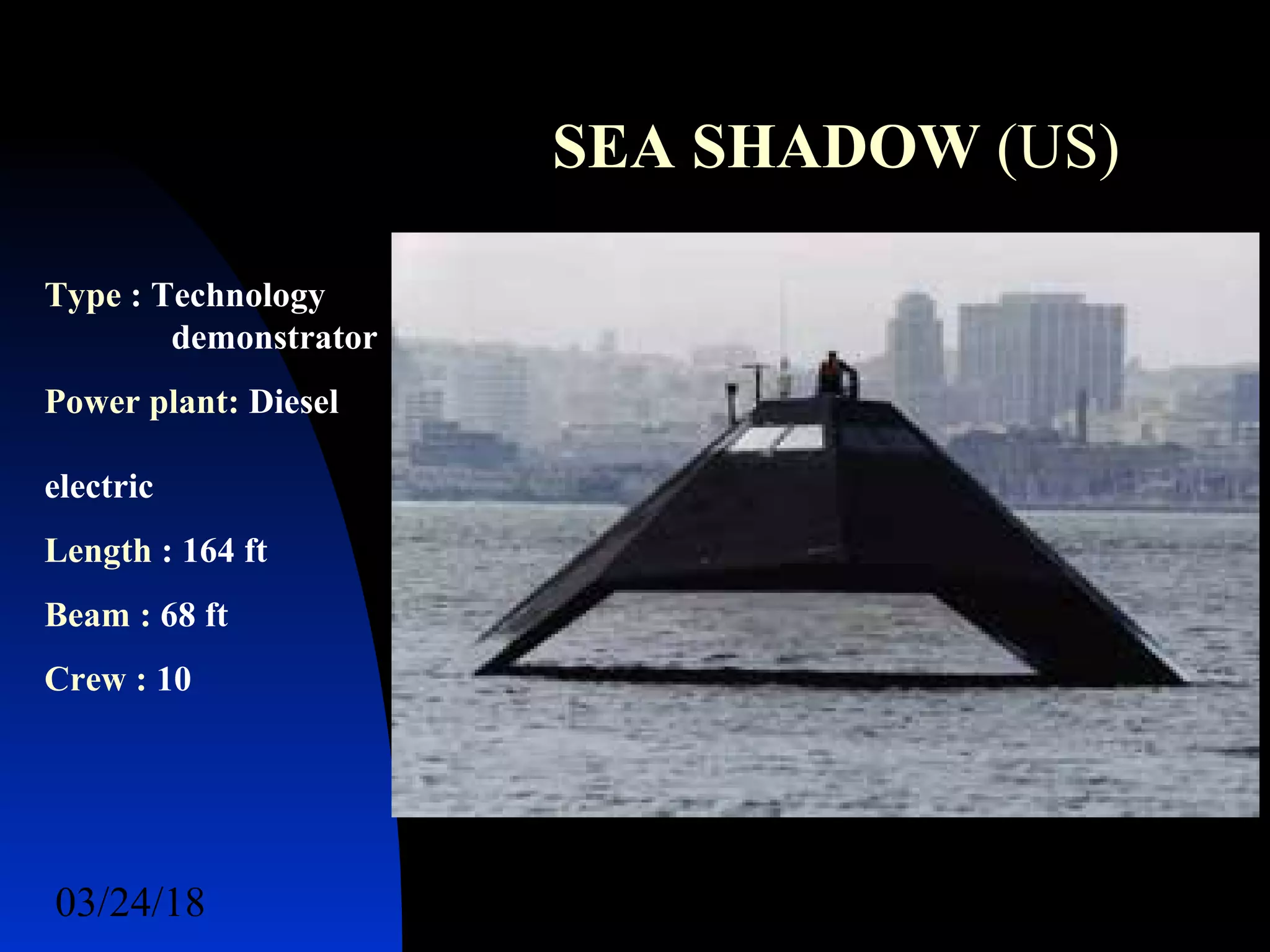
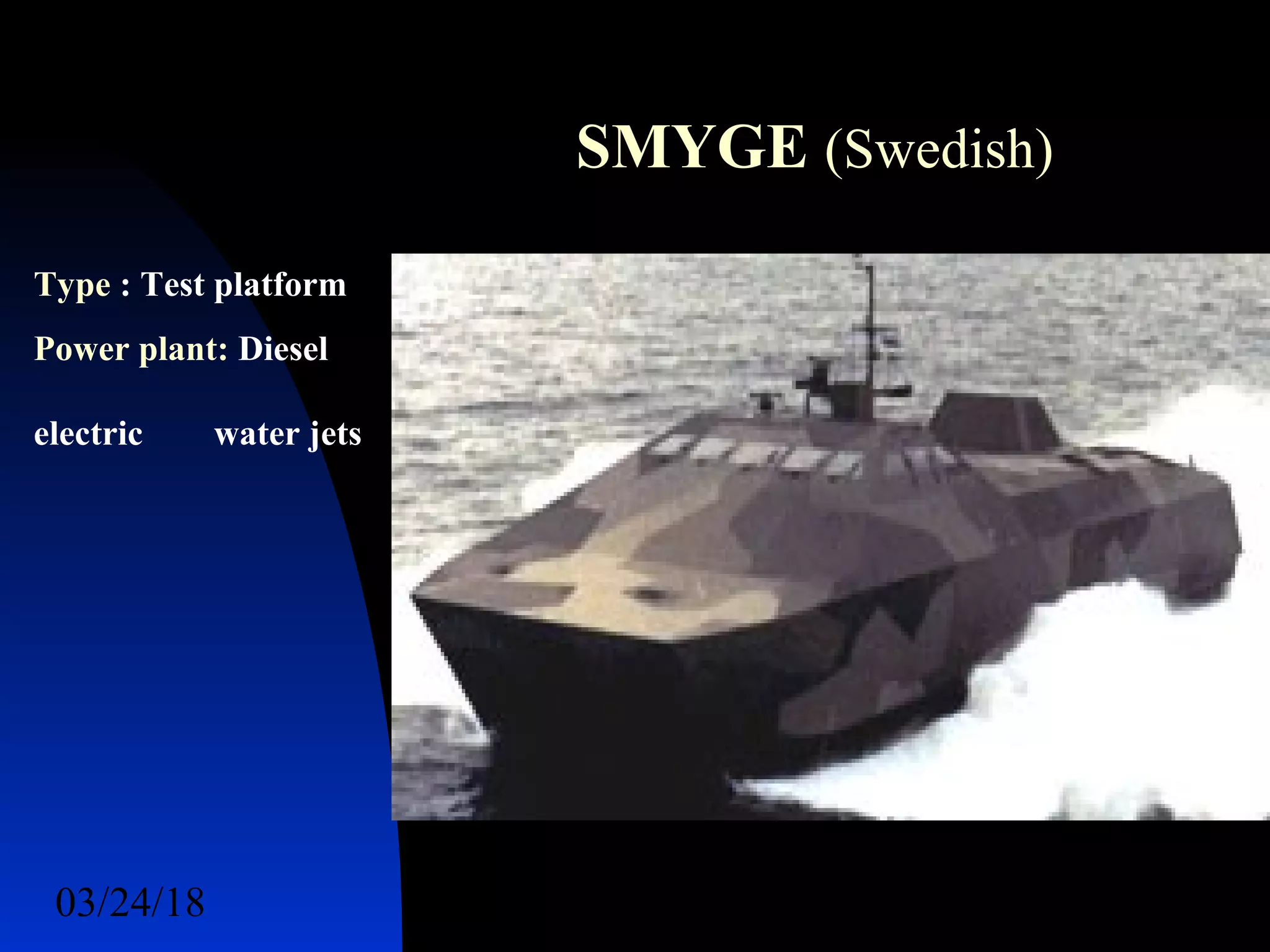
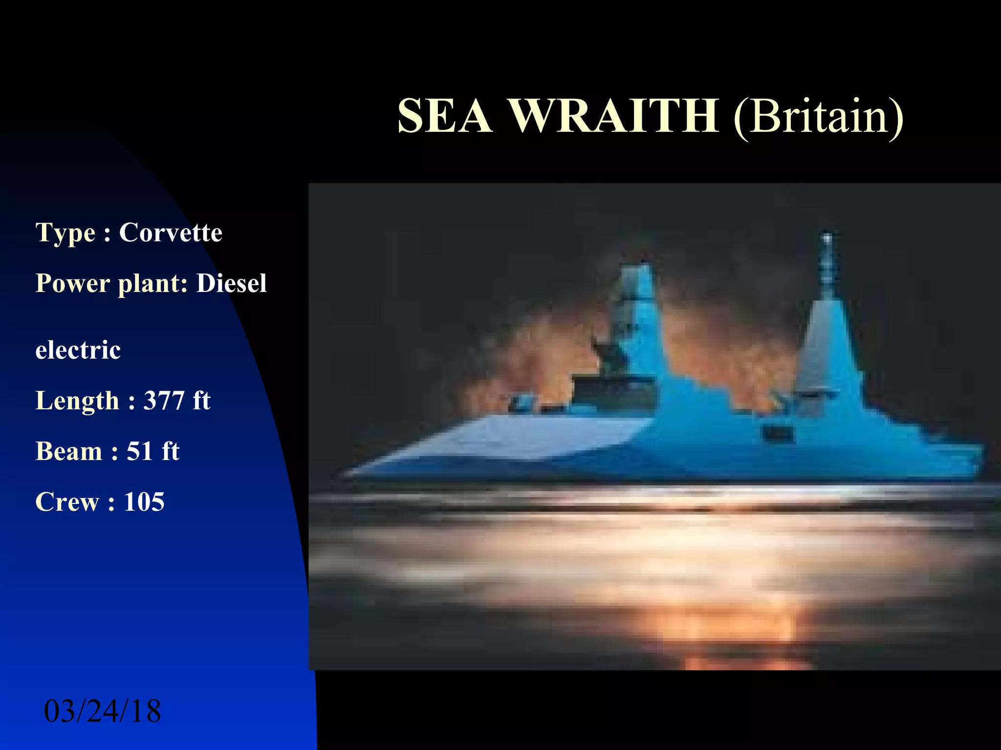
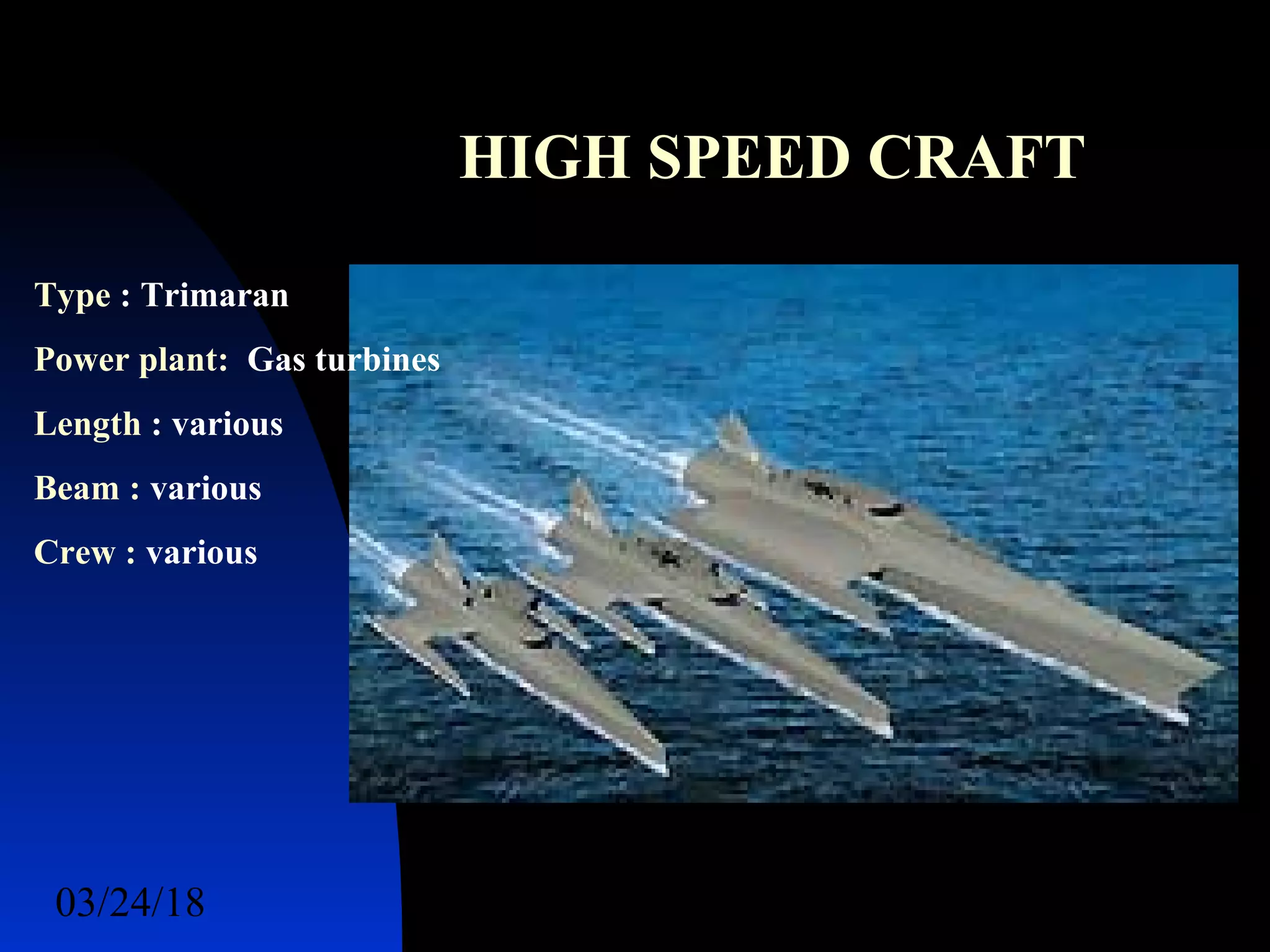

The document discusses various topics related to naval stealth technology including radar cross section (RCS) reduction techniques. It provides information on radar frequencies and functions, radar working principles, RCS prediction methods, and examples of stealth ships. Key points covered include how shaping, radar absorbing materials, and passive/active cancellation can be used to reduce the RCS and vulnerability of detection of naval vessels. Prediction software, instrumentation systems, and examples of reduced RCS for components like gun barrels are also summarized.


![Coded Agents – with UiPath SDK + LangGraph [Virtual Hands-on Workshop]](https://cdn.slidesharecdn.com/ss_thumbnails/codedagentsdeck-251215155422-5497c599-thumbnail.jpg?width=640&height=640&fit=bounds)


