This document provides an overview of transformers and per unit analysis in power systems. Key points include:
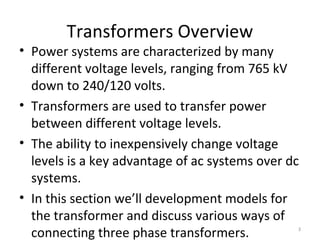
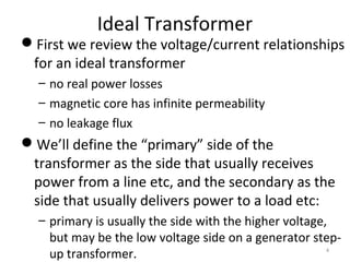
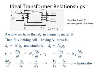
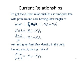
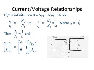
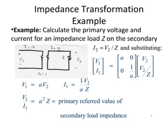
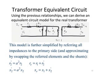
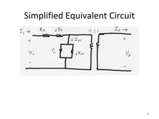
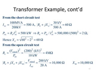
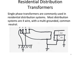
1) Transformers are used to transfer power between different voltage levels in power systems. An ideal transformer model and a more accurate model accounting for losses and leakage flux are described.
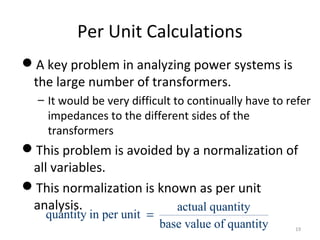
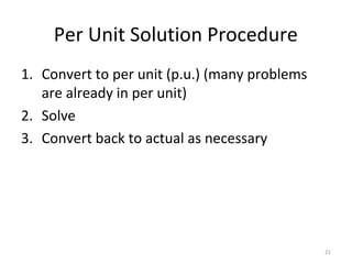
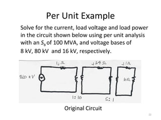
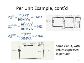
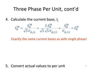
2) Per unit analysis is introduced as a method to normalize variables across different voltage bases. All values are expressed relative to selected system base values.
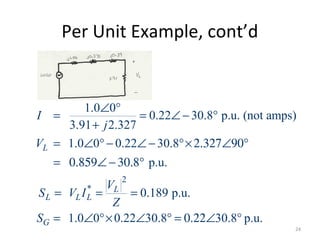
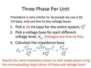
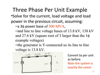
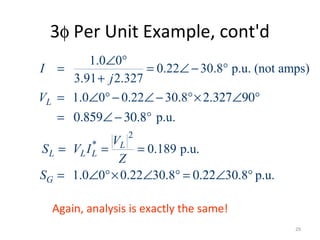
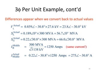
3) Examples of per unit analysis are provided for both single phase and three phase systems, showing how quantities can be converted between per unit and actual values.