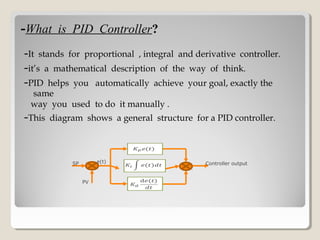
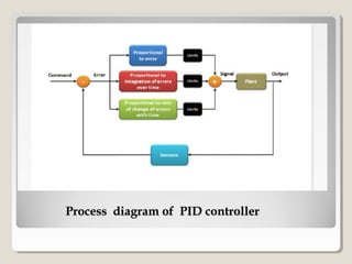
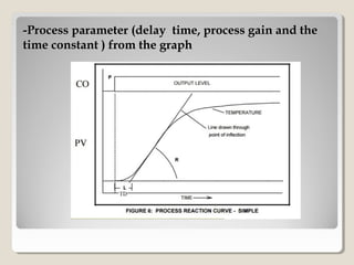
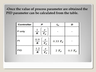
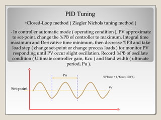
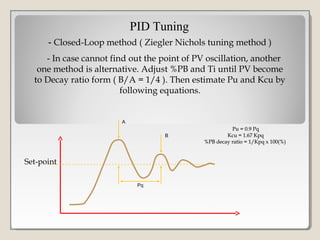
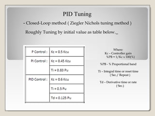
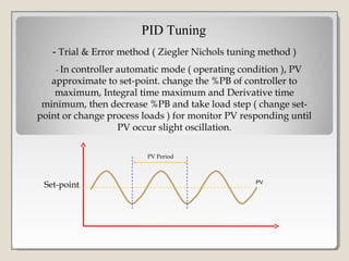
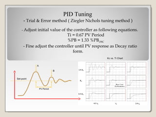
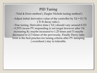
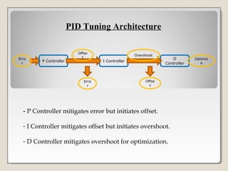
PID CONTROLLER
TUNING
BY MITESH KUMAR
ROLL NO-10300513026
Applied Electronics & Instrumentation Engg.
Haldia Institute Of Technology
CONTENTSCONTENTS
-WHAT IS PID CONTROLLER?
-WHAT DO YOU NEED TO FORM A PID CONTROLLER?
-HOW DO YOU TUNE YOUR PID PARAMETERS TO THE
OPTIMAL RESPONSE?
-WHAT PERFORMANCE CRITERION SHOULD BE USE FOR
THE SELECTION AND THE TUNING OF THE
CONTROLLER?
-PID TUNING BY( ZIEGLER NICHOLUS METHOD)
:OPEN LOOP METHOD
: CLOSED LOOP METHOD
: TRIAL AND ERROR METHOD
-PID ARCHITECTURE
--What is PID ControllerWhat is PID Controller??
-It stands for proportional , integral and derivative controller.
-it’s a mathematical description of the way of think.
-PID helps you automatically achieve your goal, exactly the
same
way you used to do it manually .
-This diagram shows a general structure for a PID controller.
SP
PV
Controller outpute(t)
Process diagram of PID controllerProcess diagram of PID controller
--What do you need to form a PID Controller?What do you need to form a PID Controller?
-you need the following six basic elements:
-Error: it is the difference between your command and the output
the output of the controller.
-Proportional term P: it is a constant directly related to the amount
of the error .if you have large error ,the term gives you a large
output. and if you have a small error ,it will give you a small
output the simple! The p term affects the speed to reach your
target.
-Integral term: it is constant related to the integration (summation)
of errors over time. If your error is increasing, this term give you a
large output. however if the error is decreasing ,the I term give
you a small output.thu its used to the fine tune your results ,i.e,
when u almost reach your goal ,the p term canot serve you any
more
I term is the one you can count on to drive you error signal to zero.
How to tune PID Controller?How to tune PID Controller?
-Derivative term D:it is constant related to the rate of change
(derivative) of errors with time .
-what does this mean?
it means that if your error signal changes rapidly , i.e., you have a
highly dynamic system like a multi copter , the D term will give
you higher output to catch up with the changes .on the other hand if
your error changes slowly like in the room temperature example ,
the D term won’t find amplify . Thus it ‘ll look for your noise
signal(which usually has a high frequency ) and amplify it to make
your life miserable!
-the D term is a very dangerous controller if it’s not tuned perfectly!
Limits: you need to limit the output of each of the previous controller!
-Finally , you need your system of course unless you are satisfied with
controller
-How do you tune your PID parameters to the-How do you tune your PID parameters to the
optimal response?optimal response?
-Most often tuning is an art more than a science.
- Observe the system and use your intuitive guess and logical
Reasoning.
Here are seven golden rules for general PID tuning:
1.After nulling all the parameters ,increase the P term so that the
output reaches the target in the shortest possible time.
2.If your output starts oscillating ,it means you have too much P.
lower your P term until the oscillation disappears. you will end up
Slightly higher or lower than your target. don’t worry; we will fix that
in the next step.
3.Now increase I term slightly until your errors goes away. note that
usual I values are very small(in the order of one thousandth for
example)
-PID TUNING-PID TUNING
-and they are dependent on the update rate of your PID loop.
The I term is very useful when you have outside error signal affecting
your system (e.g. wind in a multi copter).
-It drives your error to zero whenever possible.
4.If you feel your output is oscillating and it was not before you
adjusted your I term , lower I slightly.
5.For many slow dynamic system ,your job is almost done! You just
have to jump to the last step . when dealing with highly dynamic
system however you need to adjust the D term .
If you feel your output “lagging” behind the error variation and trying
hard but falling to catch them ,increase this term slightly.
6.f your system starts to oscillate with high frequency and small
transition, you probably have to much D term which is amplifying
Your noise. Decrease D appropriately. If your system ,however has to
much noise it is better to keep this parameter to zero.
PID TUNINGPID TUNING
7.At the last watch your limit ! If you were changing the previous
parameters without any noticeable change in the output ,
Remember that limits cut down your output signal. Increase them
Probably but be careful not to burn or saturate your system.
Simulation figure of PID Controller
-What performance criterion should be use for the
selection and the tuning of the controller?
-There are a variety of performance criteria we could use ,such as:
-Keep the maximum deviation (error) as small as possible .
-Achieve short settling time .
-Minimize the integral of the errors until the process has settled to
its desired set point, and so on
-The most often quoted simple performance criteria are:
-overshoot(A/B)
-Rise time
-Settling time
- Decay ratio(C/A)
Performance criteriaPerformance criteria
PID TuningPID Tuning
-- OPEN LOOP METHOD(ZIEGLER NICHOLUS METHOD)OPEN LOOP METHOD(ZIEGLER NICHOLUS METHOD)
-It is done in manual mode
-It is way of relating the process parameters( i.e delay time ,process
gain and time constant) to the controller parameters (i.e .controller
gain and reset time)
-It has been developed for use on delay-followed -by-first-order-lag
processes.
-Process parameter (delay time, process gain and the-Process parameter (delay time, process gain and the
time constant ) from the graphtime constant ) from the graph
-Once the value of process parameter are obtained the-Once the value of process parameter are obtained the
PID parameter can be calculated from the table.PID parameter can be calculated from the table.
-Closed-Loop method (Closed-Loop method ( Ziegler Nichols tuning methodZiegler Nichols tuning method )
PID TuningPID Tuning
- In controller automatic mode ( operating condition ), PV approximate
to set-point. change the %PB of controller to maximum, Integral time
maximum and Derivative time minimum, then decrease %PB and take
load step ( change set-point or change process loads ) for monitor PV
responding until PV occur slight oscillation. Record %PB of oscillate
condition ( Ultimate controller gain, Kcu ) and Band width ( ultimate
period, Pu ).
Set-point
Pu
PV
%PB osc = 1/Kcu x 100(%)%PB osc = 1/Kcu x 100(%)
- Closed-Loop method ( Ziegler Nichols tuning method )
PID Tuning
- In case cannot find out the point of PV oscillation, another
one method is alternative. Adjust %PB and Ti until PV become
to Decay ratio form ( B/A = 1/4 ). Then estimate Pu and Kcu by
following equations.
Set-point
Pq
A
B
Pu = 0.9 PqPu = 0.9 Pq
Kcu = 1.67 KpqKcu = 1.67 Kpq
%PB decay ratio = 1/Kpq x 100(%)%PB decay ratio = 1/Kpq x 100(%)
- Closed-Loop method ( Ziegler Nichols tuning method )
PID Tuning
Roughly Tuning by initial value as table below.
Where:Where:
Kc – Controller gainKc – Controller gain
%PB = 1/Kc x 100(%)%PB = 1/Kc x 100(%)
%PB - % Proportional band%PB - % Proportional band
Ti – Integral time or reset timeTi – Integral time or reset time
( Sec./ Repeat )( Sec./ Repeat )
Td – Derivative time or rateTd – Derivative time or rate
( Sec.)( Sec.)
- Trial & Error method ( Ziegler Nichols tuning method )
PID Tuning
- In controller automatic mode ( operating condition ), PV
approximate to set-point. change the %PB of controller to
maximum, Integral time maximum and Derivative time
minimum, then decrease %PB and take load step ( change set-
point or change process loads ) for monitor PV responding until
PV occur slight oscillation.
Set-point
PV Period
PV
- Trial & Error method ( Ziegler Nichols tuning method )
PID Tuning
- Adjust initial value of the controller as following equations.
Ti = 0.67 PV Period
%PB = 1.33 %PBOSC
- Fine adjust the controller until PV response as Decay ratio
form.
Set-point
PV Period
A
B
Kc vs. Ti Chart
- Trial & Error method ( Ziegler Nichols tuning method )
PID Tuning
- Adjust initial derivative value of the controller by Td = 0.1 Ti
( Ti @ decay ratio ).
- Fine tuning, Derivative time ( Td ) should vary around 0.1Ti
– 0.25Ti incase PV responding is not target however after Td
increasing Kc maybe increased to 1.25 times and Ti maybe
decreased to 2/3 times of the previously, Finally Decry ratio
form is the best practice for tuning criteria after PV damping
( overshoot ) stay in tolerable.
- P Controller mitigates error but initiates offset.
- I Controller mitigates offset but initiates overshoot.
- D Controller mitigates overshoot for optimization.
PID Tuning Architecture
Erro
r
P Controller I Controller
D
Controller
Optimiz
e
Offse
t
Erro
r
Overshoot
Offse
t
Pid controller by Mitesh Kumar

Pid controller by Mitesh Kumar

  • 1.
    PID CONTROLLER TUNING BY MITESHKUMAR ROLL NO-10300513026 Applied Electronics & Instrumentation Engg. Haldia Institute Of Technology
  • 2.
    CONTENTSCONTENTS -WHAT IS PIDCONTROLLER? -WHAT DO YOU NEED TO FORM A PID CONTROLLER? -HOW DO YOU TUNE YOUR PID PARAMETERS TO THE OPTIMAL RESPONSE? -WHAT PERFORMANCE CRITERION SHOULD BE USE FOR THE SELECTION AND THE TUNING OF THE CONTROLLER? -PID TUNING BY( ZIEGLER NICHOLUS METHOD) :OPEN LOOP METHOD : CLOSED LOOP METHOD : TRIAL AND ERROR METHOD -PID ARCHITECTURE
  • 3.
    --What is PIDControllerWhat is PID Controller?? -It stands for proportional , integral and derivative controller. -it’s a mathematical description of the way of think. -PID helps you automatically achieve your goal, exactly the same way you used to do it manually . -This diagram shows a general structure for a PID controller. SP PV Controller outpute(t)
  • 4.
    Process diagram ofPID controllerProcess diagram of PID controller
  • 5.
    --What do youneed to form a PID Controller?What do you need to form a PID Controller? -you need the following six basic elements: -Error: it is the difference between your command and the output the output of the controller. -Proportional term P: it is a constant directly related to the amount of the error .if you have large error ,the term gives you a large output. and if you have a small error ,it will give you a small output the simple! The p term affects the speed to reach your target. -Integral term: it is constant related to the integration (summation) of errors over time. If your error is increasing, this term give you a large output. however if the error is decreasing ,the I term give you a small output.thu its used to the fine tune your results ,i.e, when u almost reach your goal ,the p term canot serve you any more I term is the one you can count on to drive you error signal to zero.
  • 6.
    How to tunePID Controller?How to tune PID Controller? -Derivative term D:it is constant related to the rate of change (derivative) of errors with time . -what does this mean? it means that if your error signal changes rapidly , i.e., you have a highly dynamic system like a multi copter , the D term will give you higher output to catch up with the changes .on the other hand if your error changes slowly like in the room temperature example , the D term won’t find amplify . Thus it ‘ll look for your noise signal(which usually has a high frequency ) and amplify it to make your life miserable! -the D term is a very dangerous controller if it’s not tuned perfectly! Limits: you need to limit the output of each of the previous controller! -Finally , you need your system of course unless you are satisfied with controller
  • 7.
    -How do youtune your PID parameters to the-How do you tune your PID parameters to the optimal response?optimal response? -Most often tuning is an art more than a science. - Observe the system and use your intuitive guess and logical Reasoning. Here are seven golden rules for general PID tuning: 1.After nulling all the parameters ,increase the P term so that the output reaches the target in the shortest possible time. 2.If your output starts oscillating ,it means you have too much P. lower your P term until the oscillation disappears. you will end up Slightly higher or lower than your target. don’t worry; we will fix that in the next step. 3.Now increase I term slightly until your errors goes away. note that usual I values are very small(in the order of one thousandth for example)
  • 8.
    -PID TUNING-PID TUNING -andthey are dependent on the update rate of your PID loop. The I term is very useful when you have outside error signal affecting your system (e.g. wind in a multi copter). -It drives your error to zero whenever possible. 4.If you feel your output is oscillating and it was not before you adjusted your I term , lower I slightly. 5.For many slow dynamic system ,your job is almost done! You just have to jump to the last step . when dealing with highly dynamic system however you need to adjust the D term . If you feel your output “lagging” behind the error variation and trying hard but falling to catch them ,increase this term slightly. 6.f your system starts to oscillate with high frequency and small transition, you probably have to much D term which is amplifying Your noise. Decrease D appropriately. If your system ,however has to much noise it is better to keep this parameter to zero.
  • 9.
    PID TUNINGPID TUNING 7.Atthe last watch your limit ! If you were changing the previous parameters without any noticeable change in the output , Remember that limits cut down your output signal. Increase them Probably but be careful not to burn or saturate your system. Simulation figure of PID Controller
  • 10.
    -What performance criterionshould be use for the selection and the tuning of the controller? -There are a variety of performance criteria we could use ,such as: -Keep the maximum deviation (error) as small as possible . -Achieve short settling time . -Minimize the integral of the errors until the process has settled to its desired set point, and so on -The most often quoted simple performance criteria are: -overshoot(A/B) -Rise time -Settling time - Decay ratio(C/A)
  • 11.
  • 12.
    PID TuningPID Tuning --OPEN LOOP METHOD(ZIEGLER NICHOLUS METHOD)OPEN LOOP METHOD(ZIEGLER NICHOLUS METHOD) -It is done in manual mode -It is way of relating the process parameters( i.e delay time ,process gain and time constant) to the controller parameters (i.e .controller gain and reset time) -It has been developed for use on delay-followed -by-first-order-lag processes.
  • 13.
    -Process parameter (delaytime, process gain and the-Process parameter (delay time, process gain and the time constant ) from the graphtime constant ) from the graph
  • 14.
    -Once the valueof process parameter are obtained the-Once the value of process parameter are obtained the PID parameter can be calculated from the table.PID parameter can be calculated from the table.
  • 15.
    -Closed-Loop method (Closed-Loopmethod ( Ziegler Nichols tuning methodZiegler Nichols tuning method ) PID TuningPID Tuning - In controller automatic mode ( operating condition ), PV approximate to set-point. change the %PB of controller to maximum, Integral time maximum and Derivative time minimum, then decrease %PB and take load step ( change set-point or change process loads ) for monitor PV responding until PV occur slight oscillation. Record %PB of oscillate condition ( Ultimate controller gain, Kcu ) and Band width ( ultimate period, Pu ). Set-point Pu PV %PB osc = 1/Kcu x 100(%)%PB osc = 1/Kcu x 100(%)
  • 16.
    - Closed-Loop method( Ziegler Nichols tuning method ) PID Tuning - In case cannot find out the point of PV oscillation, another one method is alternative. Adjust %PB and Ti until PV become to Decay ratio form ( B/A = 1/4 ). Then estimate Pu and Kcu by following equations. Set-point Pq A B Pu = 0.9 PqPu = 0.9 Pq Kcu = 1.67 KpqKcu = 1.67 Kpq %PB decay ratio = 1/Kpq x 100(%)%PB decay ratio = 1/Kpq x 100(%)
  • 17.
    - Closed-Loop method( Ziegler Nichols tuning method ) PID Tuning Roughly Tuning by initial value as table below. Where:Where: Kc – Controller gainKc – Controller gain %PB = 1/Kc x 100(%)%PB = 1/Kc x 100(%) %PB - % Proportional band%PB - % Proportional band Ti – Integral time or reset timeTi – Integral time or reset time ( Sec./ Repeat )( Sec./ Repeat ) Td – Derivative time or rateTd – Derivative time or rate ( Sec.)( Sec.)
  • 18.
    - Trial &Error method ( Ziegler Nichols tuning method ) PID Tuning - In controller automatic mode ( operating condition ), PV approximate to set-point. change the %PB of controller to maximum, Integral time maximum and Derivative time minimum, then decrease %PB and take load step ( change set- point or change process loads ) for monitor PV responding until PV occur slight oscillation. Set-point PV Period PV
  • 19.
    - Trial &Error method ( Ziegler Nichols tuning method ) PID Tuning - Adjust initial value of the controller as following equations. Ti = 0.67 PV Period %PB = 1.33 %PBOSC - Fine adjust the controller until PV response as Decay ratio form. Set-point PV Period A B Kc vs. Ti Chart
  • 20.
    - Trial &Error method ( Ziegler Nichols tuning method ) PID Tuning - Adjust initial derivative value of the controller by Td = 0.1 Ti ( Ti @ decay ratio ). - Fine tuning, Derivative time ( Td ) should vary around 0.1Ti – 0.25Ti incase PV responding is not target however after Td increasing Kc maybe increased to 1.25 times and Ti maybe decreased to 2/3 times of the previously, Finally Decry ratio form is the best practice for tuning criteria after PV damping ( overshoot ) stay in tolerable.
  • 21.
    - P Controllermitigates error but initiates offset. - I Controller mitigates offset but initiates overshoot. - D Controller mitigates overshoot for optimization. PID Tuning Architecture Erro r P Controller I Controller D Controller Optimiz e Offse t Erro r Overshoot Offse t