Downloaded 22 times

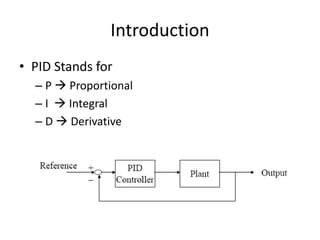
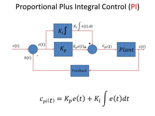
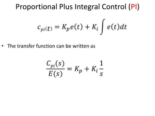
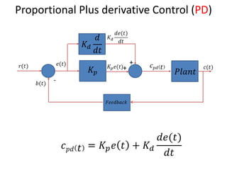
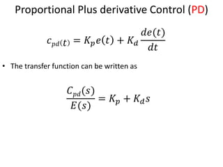
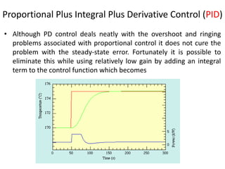
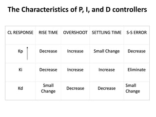

The document discusses PID controllers, detailing their components: Proportional, Integral, and Derivative, and their roles in control systems. It highlights the advantages and disadvantages of each controller type, emphasizing their applicability, tuning methods, and effects on system stability. PID controllers are noted for their widespread use in industry, with over half of existing controllers being PID or modified versions.