This document summarizes pneumatic process control. It discusses that pneumatic controls are powered by compressed air and are safer than electronic controls in explosive environments like chemical plants. It then describes the basic components of a closed-loop pneumatic control system including a controller, actuator and measuring device. Finally, it explains some common pneumatic control devices like flapper nozzles, volume boosters, and force balance transducers and how proportional and proportional-integral controllers work in pneumatic systems.
Prepared by: Bestin V Kallely
Karunya University
M.Tech Mechanical
Engg.
PR11ME1008
2.
• Pneumatic controlsare powered by compressed
air.
• Pneumatic Process control are safer than
Electronic and controller's, when used in
Explosive atmosphere like Chemical or
Petrochemical plats.
3.
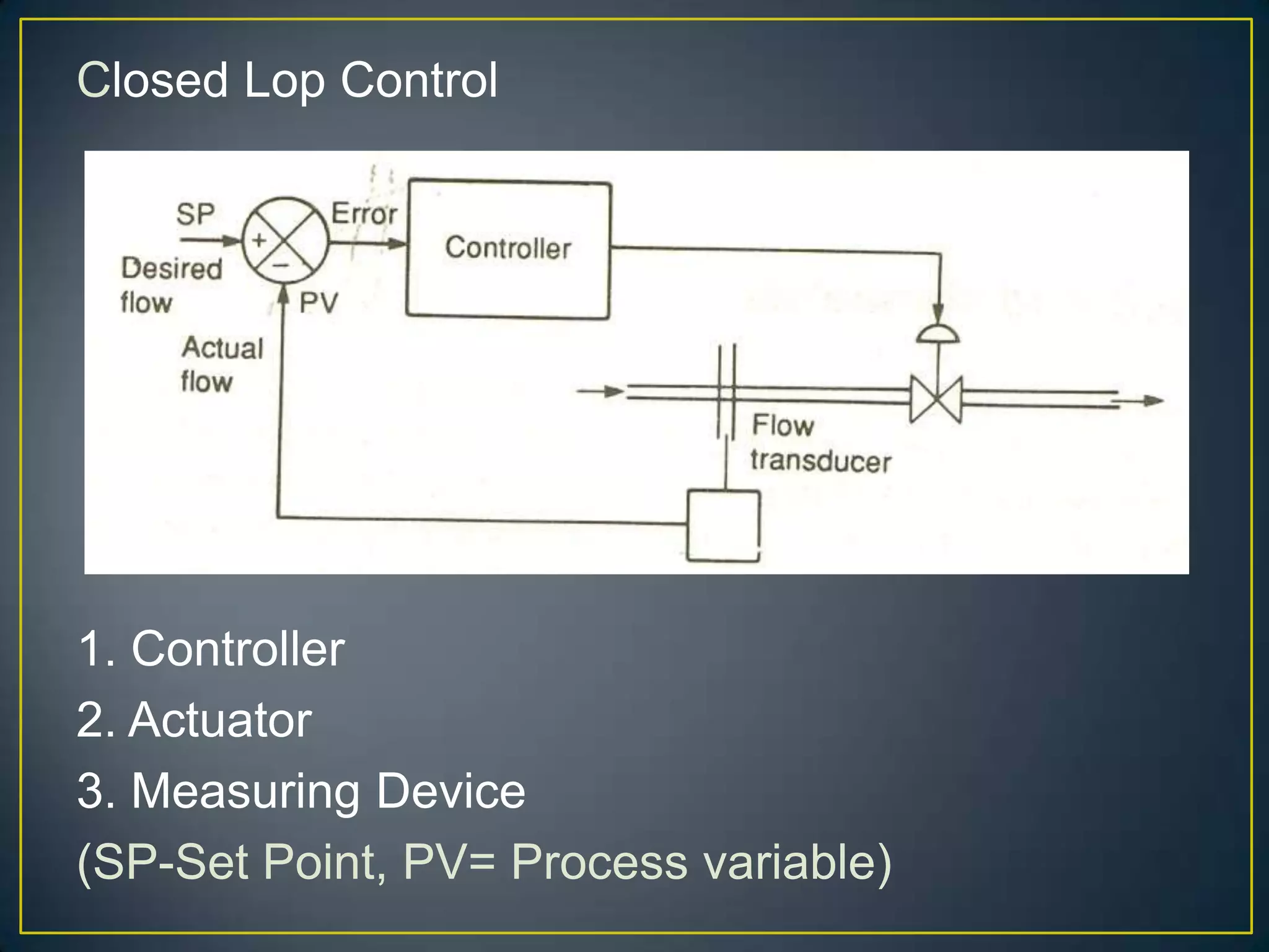
Closed Lop Control
1.Controller
2. Actuator
3. Measuring Device
(SP-Set Point, PV= Process variable)
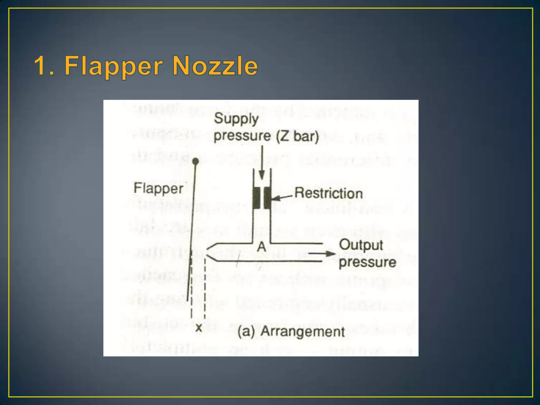
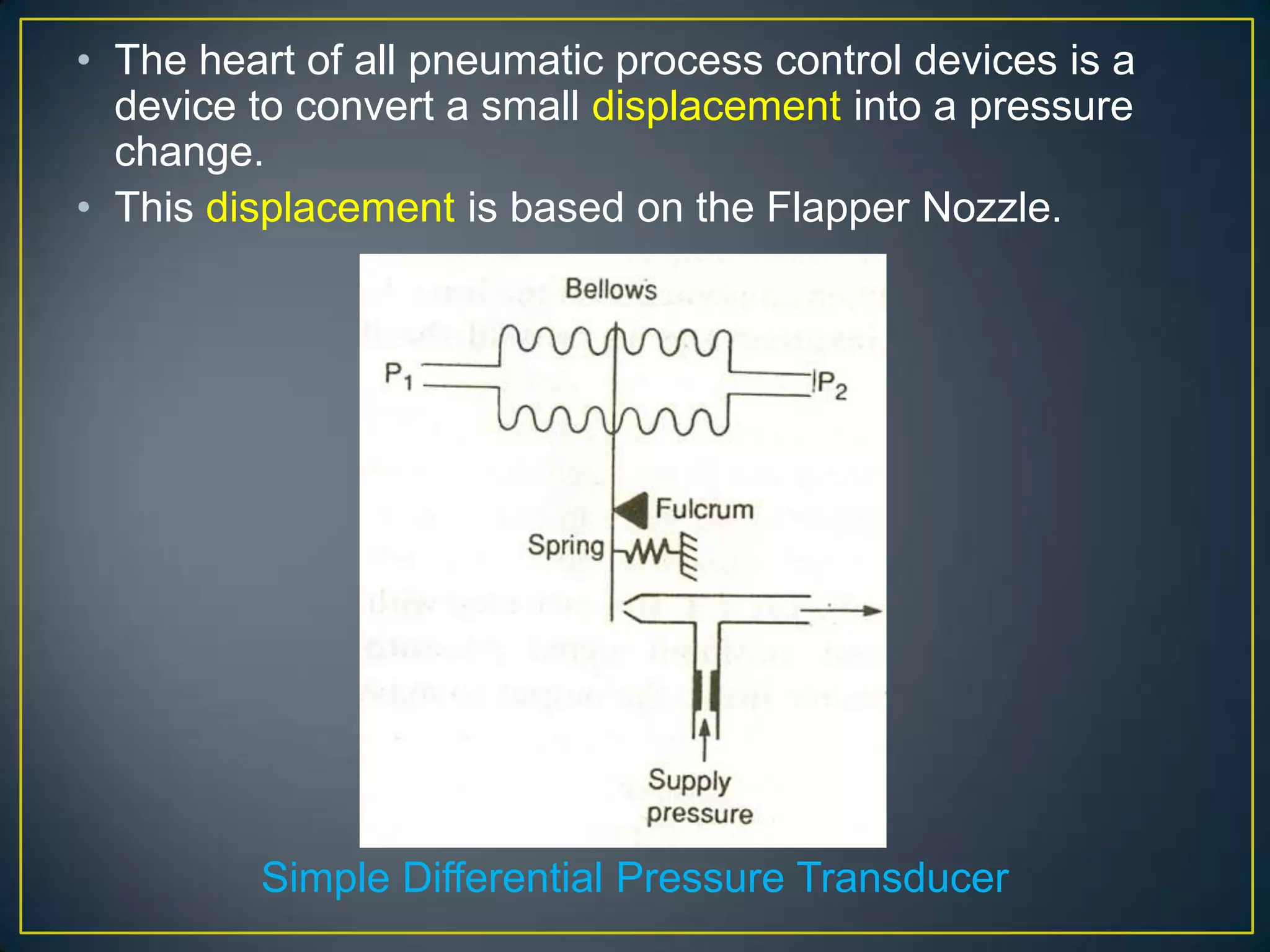
• The heartof all pneumatic process control devices is a
device to convert a small displacement into a pressure
change.
• This displacement is based on the Flapper Nozzle.
Simple Differential Pressure Transducer
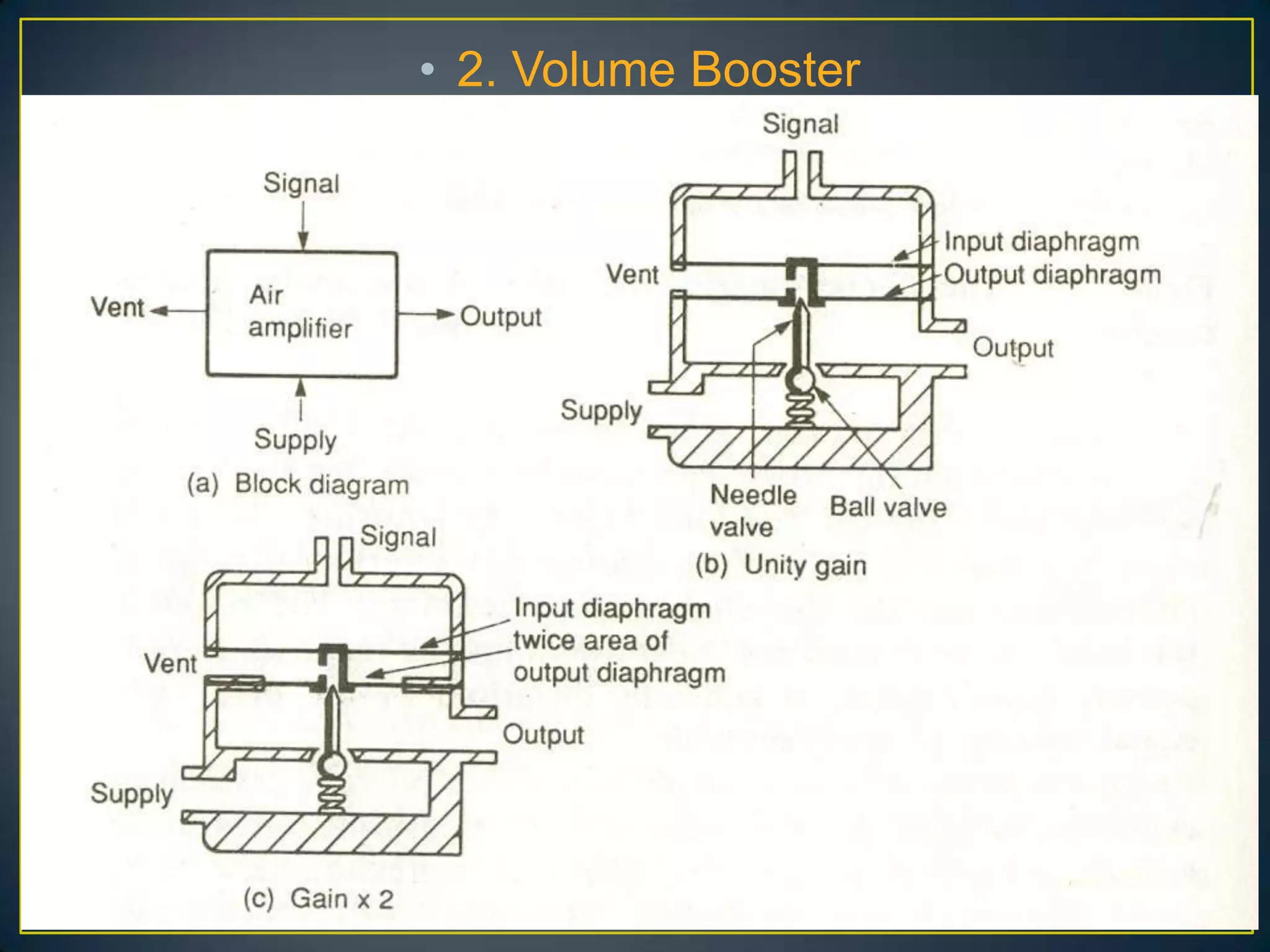
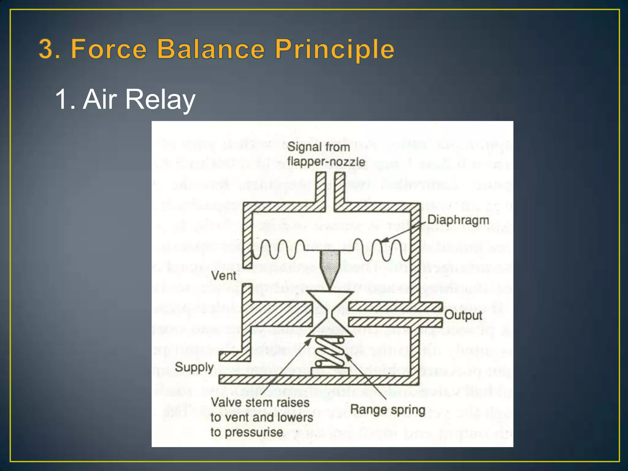
• An increasein input signal cause air to pas from
the supply to the load, while a decreasing input
signal cause air to vent from the load.
12.
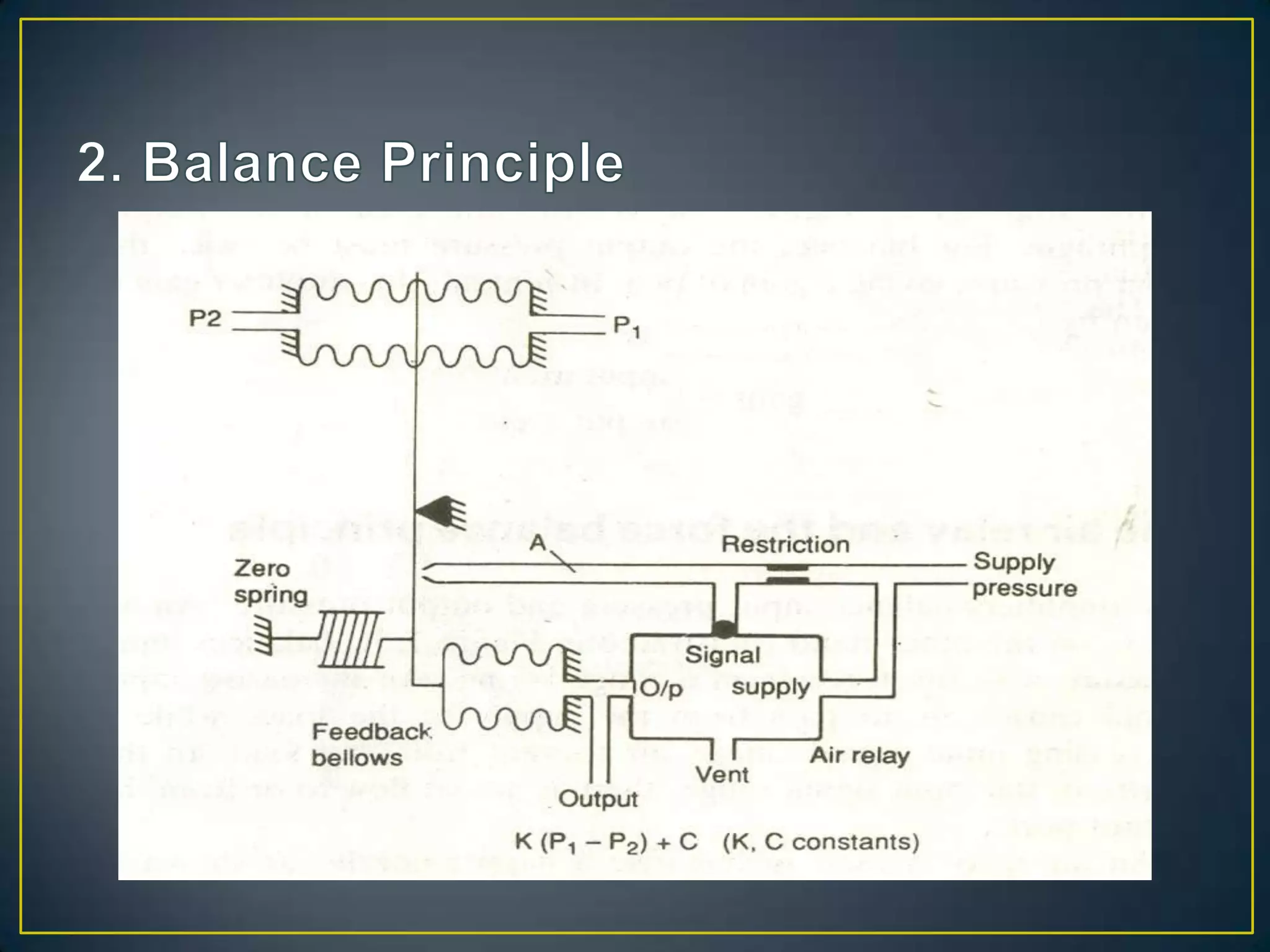
• The forcefrom the feedback bellows match
the force from the input signal bellows and
output pressure directly proportional to
(P1-P2)
13.
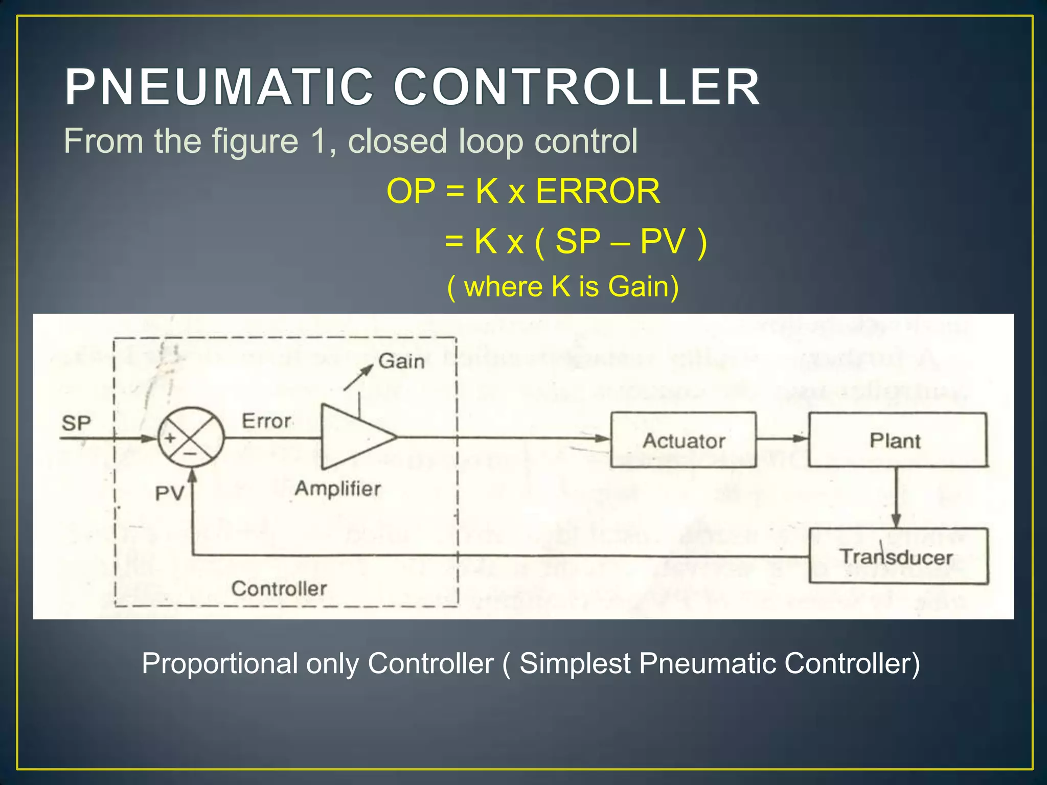
From the figure1, closed loop control
OP = K x ERROR
= K x ( SP – PV )
( where K is Gain)
Proportional only Controller ( Simplest Pneumatic Controller)
15.
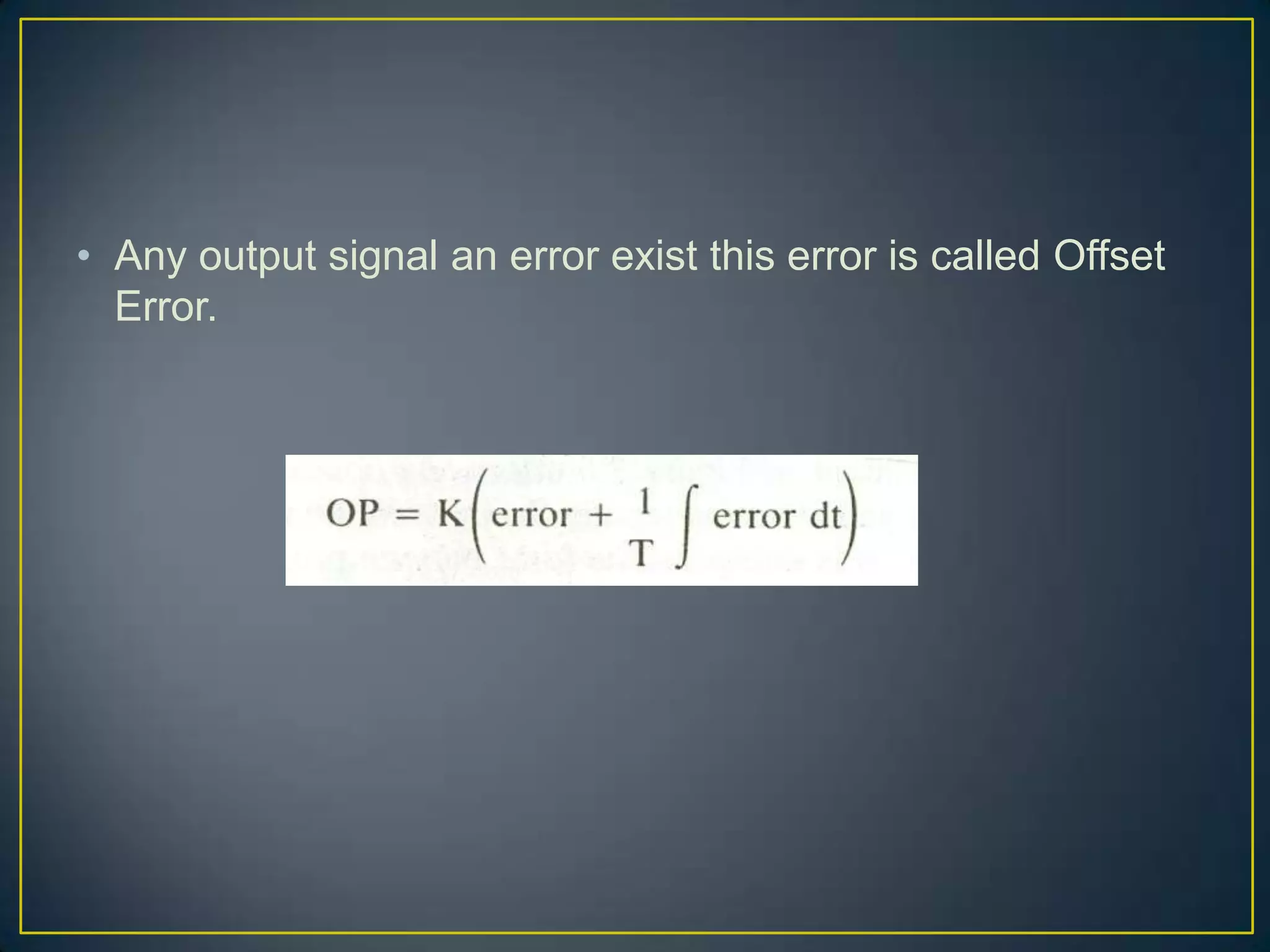
• Any outputsignal an error exist this error is called Offset
Error.