Downloaded 243 times

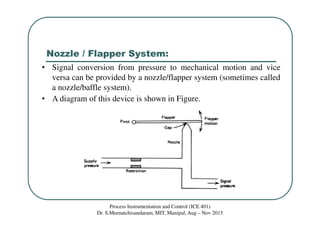
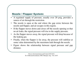
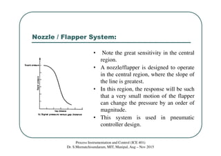
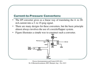
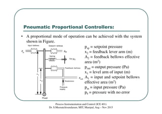
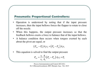
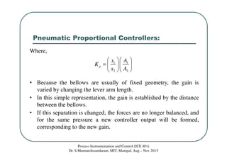
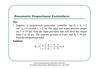

The document describes the operation of a pneumatic nozzle/flapper system used in pneumatic controllers. It discusses how a nozzle/flapper system can convert a pressure signal to mechanical motion and vice versa using a regulated air supply and a nozzle and flapper. It then discusses how this system is used in current-to-pressure converters to translate a 4-20 mA current signal to a 3-15 psi pressure signal. Finally, it describes how a proportional mode can be achieved in a pneumatic controller using bellows, levers, and a nozzle/flapper system to balance pressures and provide a controller output proportional to the input error.