This document summarizes a lab where students characterized the performance of PID and bang-bang control schemes on a motor/flywheel system using LabVIEW. Students implemented both PID and bang-bang control and analyzed the performance of each by varying control parameters. PID control had smoother operation than bang-bang and was better at compensating for rise time, stability, and steady-state error. Bang-bang control resulted in more erratic behavior and was unable to eliminate steady-state error. Students also tuned the PID controller manually and using the Ziegler-Nichols method to minimize error.
![<Section 7042_Lab2> Double Click to Edit 2
2
proportional gain value. The proportional gain value is set three
different values (0.0001, 0.0005 and 0.001) and data is recorded
for each of the values. After this is done, the proportional gain
is increased until the system becomes unstable and the
associated gain is recorded.
Determining “feel” of PID gains
The “feel” of the gains is a qualitative assessment ofhow the
system responds when an opposing motion is applied to the
flywheel. In order to perform this task, the magnitude is set to
zero as well as the derivative and integral gains. The
proportional gain is then set to 0.0001 and then the flywheel is
manually rotated by the students and system response is felt.
The proportional gain is then increased by factors of 10, 100
and 1,000 and the system response is felt. This is done in a
similar fashion for the derivative gain. The derivative/integral
gains are done in a similar fashion. For the derivative gain, the
numerical derivative and tachometer input are used to compute
the error and the feel of each is assessed. For the integral gain,
the points to integrate overis assessedat 30 and then at 200 and
then compared.
Tuning the PID controller
A. Manual tuning method
The goal of manual tuning is to reduce rise time, overshoot
and steady-state error. This is done by increasing the
proportional gain until the output starts to oscillate. This gain
value is then divided in half to obtain the quarter amp decay.
Next, the integral gain is increased until the offset is corrected.
Lastly, the derivative gain is increased to reduce overshoot and
excessive response [1].
B. Ziegler-Nichols tuning method
The steps to perform the Ziegler-Nichols tuning method is
described in [2]. Essentially, students manually turn the
flywheel and release it until the systemgoes unstable and then
they slowly decrease the proportional gain value until the
systemhas a stable, oscillatory response.This gain value is 𝐾𝑢.
The associated period of one cycle of this oscillation is 𝑃𝑢. The
following equations showhowthe gains can be calculated from
these parameters.
𝐾𝑝 = 0.60𝐾𝑢 (4)
𝐾𝑖 =
2𝐾𝑝
𝑃𝑢
(5)
𝐾𝑑 =
𝐾𝑝 𝑃𝑢
8
(6)
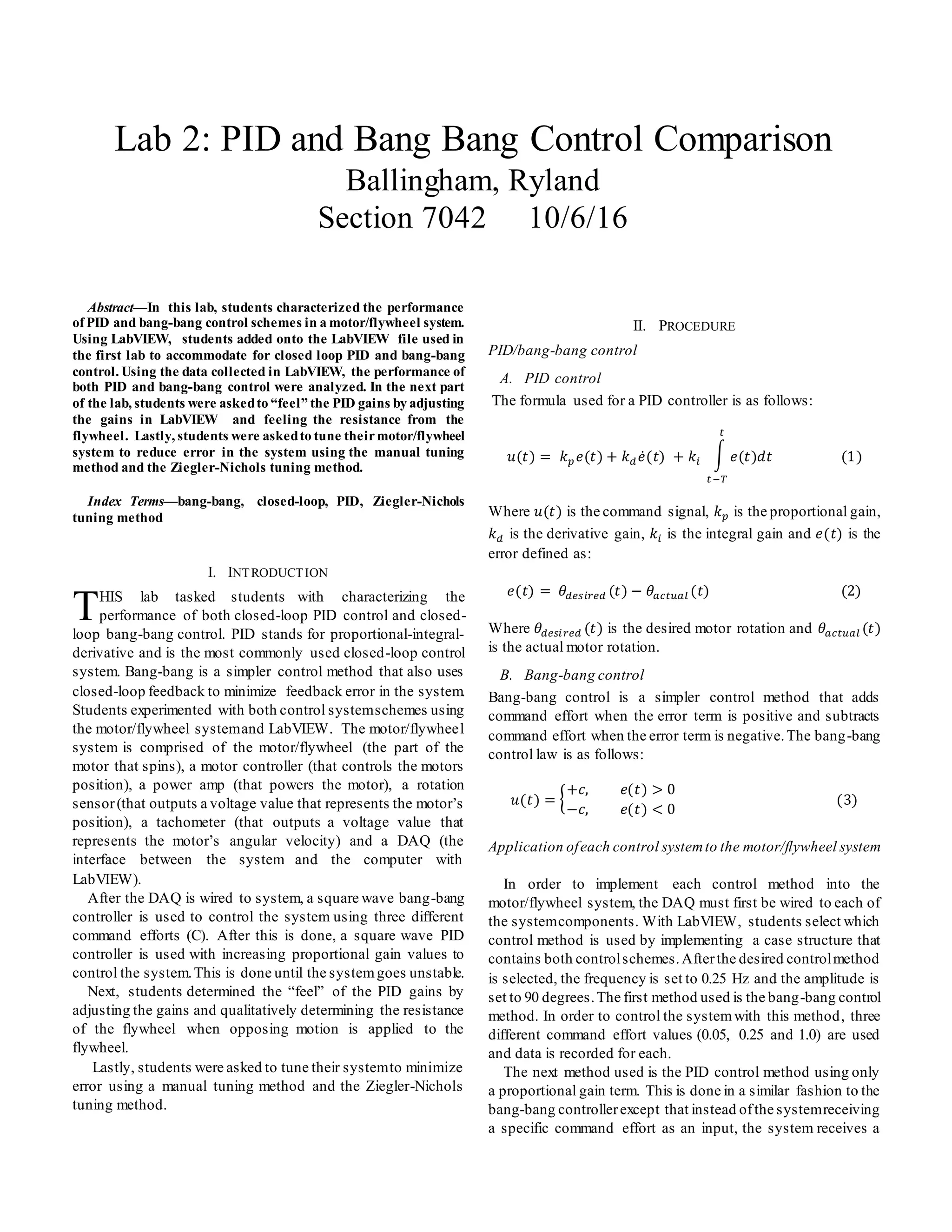
III. RESULTS
TABLE I
MEAN/STANDARD DEVIATION OF ERROR/COMMAND SIGNALS
Control
scheme
Mean,
error
Standard
deviation,error
Command,
error
Command,
standard.
deviation
Bang-bang
(C=0.05)
3.45 86.83 0.05 0
Bang-bang
(C=0.25)
-1.88 85.89 0.25 0
Bang-bang
(C=1.0)
4.94 73.65 1 0
PID
(Kp=0.0001)
11.84 89.24 0.009 5.11E-05
PID
(Kp=0.0005)
-1.14 56.83 0.018 0.022
PID
(Kp=0.001)
-2.47 59.39 0.033 0.050
Manual
tuning
0.137 52.41 0.0003 0.111
Ziegler-
Nichols
tuning
6.06 59.14 0.004 0.234
TABLE II
ROOT-MEAN SQUARE VALUES
Control
Scheme
Error, rms Command, rms
Bang-bang
(C=0.05)
86.90 0.05
Bang-bang
(C=0.25)
85.91 0.25
Bang-bang
(C=1)
73.82 1.0
PID
(Kp=0.0001)
90.02 0.009
PID
(Kp=0.0005)
56.84 0.028
PID
(Kp=0.001)
59.44 0.059
Manual-
tuning
52.41 0.111
Ziegler-
Nichols
tuning
59.46 0.145
TABLE III
RISE-TIME/OVERSHOOT VALUES
Control
Scheme
Rise-time (s) Overshoot (deg)
Bang-bang
(C=0.05)
0.281 156.78
Bang-bang
(C=0.25)
0.279 162.76
Bang-bang
(C=1)
0.262 167.89
PID
(Kp=0.0001)
N/A N/A
PID
(Kp=0.0005)
0.406 -11.26
PID
(Kp=0.001)
0.537 11.07
Manual-
tuning
0.348 5.09
Ziegler-
Nichols
tuning
0.378 8.11](https://image.slidesharecdn.com/60d07239-9b05-40d0-a61d-2201014ceb96-161224023117/75/ControlsLab2-2-2048.jpg)
![<Section 7042_Lab2> Double Click to Edit 4
4
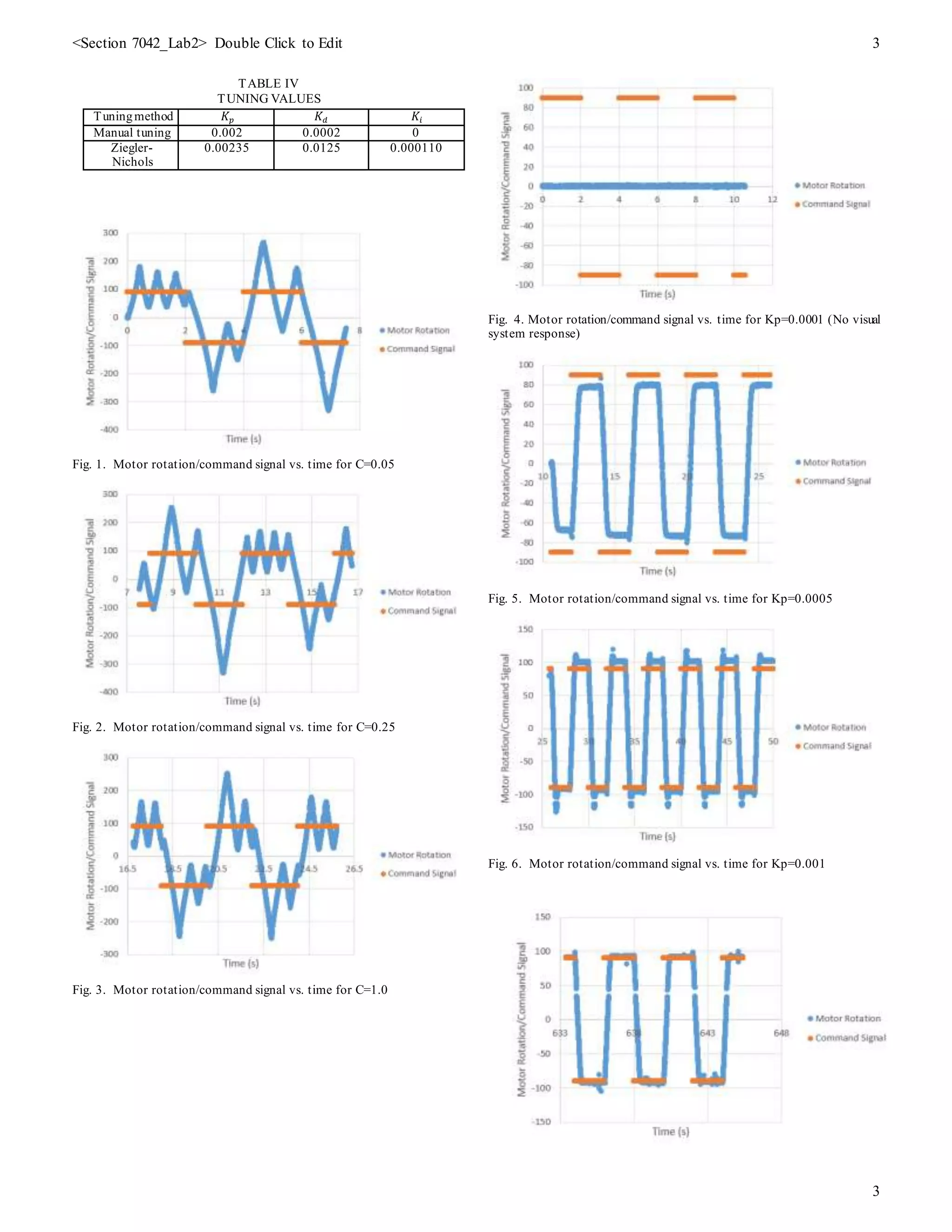
Fig. 7. Motor rotation/command signal vs. time manual tuning
IV. DISCUSSION
A. Root Mean Square of mean/standard deviation for
error/command signals
Table I shows all the values for mean and standard
deviations of the error and command signals. From table II, it
can be seen that with increasing command effort for the bang-
bang controller, the root mean square of the error signal
decreases. For the PID controller, with increasing
proportional gain, the root mean square of the error signal
decreases up until a proportional gain value of 0.005 and then
it increased. The formulas used to find these values can be
found in the appendix section
B. Bang-bang vs. PID comparison
The bang-bang and PID controllers performed much
differently. From figs 1-3, it is clear that the bang-bang
controller is much more erratic in behavior as it always has
large oscillations around the desired command signal. Because
of this, bang-bang controllers can’t compensate for steady-state
error in an efficient fashion. For bang-bang controllers,
overshoot is always going to be a problem since the controller
is either on or off. There is no condition for a bang-bang
controller in which the error is zero.
The PID controller has much a smoother operation than the
bang-bang controller as seen in figs 4-7. The PID controller is
better at compensating for rise-time, stability and steady-state
error as it has proportional gain term that is used to manipulate
rise-time, a derivative gain term for adjusting the stability of the
system and an integral gain term that focuses on reducing
steady-state error.
C. Control effort magnitude effect
When the control effort magnitude is increased for the
bang-bang controller, the rise-time decreases and the percent
overshoot increases. With large effort values,the systemgoes
unstable.
D. Effect of proportional gain value on system performance
The larger the proportional gain value, the faster the rise-
time and the more likely that overshoot will occur. If the gain
value is increased to a value too large, the system will go
unstable. This systemwent unstable at 𝐾𝑝 = 0.015.
E. “Feel” of PID gains
The higher the 𝐾𝑝 value, the more the flywheel resist manual
movements in a linear fashion (the more force used to turn to
the flywheel, the more it resists the motion). This is because the
proportional gain is proportional to position. The higher 𝐾𝑑
value, the more the flywheel fights against manual hand
movements in an incremental fashion (The faster the flywheel
is rotated, the more it resists the motion). This is because the
derivative gain is proportional to the velocity of the flywheel.
For 𝐾𝑖, there was no visual response until 𝐾𝑖 was increased to
1. From there 𝐾𝑖 was gradually decreased until the flywheel
could be manually turned without risk of injury. The system
response seemed very slow. It doesn’t resist manual hand turns
initially, but after some time the flywheel resistance gradually
increases with time. This because the error term is being
integrated over a long time interval thus the errors of position
are becoming greater and greater.
F. Tuning method Comparison
The manual tuning method had betterresults and was easier
to implement. The manual tuning method was less intricate
and allowed for the system to be tuned in a more visual
manner. The Ziegler-Nichols method was much more time
consuming as well. Table IV shows the results forboth tuning
methods.
V. CONCLUSION
A. Bang-bang vs. PID
PID is a better way to control the motor flywheel systemdue
to its less erratic behavior. Bang-bang control seems to be much
too crude to have effective closed-loop control for the
motor/flywheel system. Since PID control has gains that can be
adjusted, it is much easier to fine tune a system properly to
increase rise time, yet decrease overshoot and steady-state
errors.
B. Manual tuning vs. Ziegler-Nichols tuning
In the lab, manual tuning yielded better results than Ziegler-
Nichols tuning. This is likely because there is less error
propagation using manual tuning as it is a less arbitrary tuning
method and it is more simple to implement.
C. Ways to improve lab
Unfortunately, while performing the lab the motor that was
being used kept overheating.This was frustrating as the there
was a large amount of down time waiting for the motor to cool
off. If the lab had a better way of keeping the motors cool it
would be highly beneficial to lab efficiency.
APPENDIX
.
𝐸𝑟𝑟𝑜𝑟𝑅𝑀 𝑆 = √ 𝑀𝑒𝑎𝑛 𝐸𝑟𝑟𝑜𝑟2 + 𝑆𝑇𝐷 𝐸𝑟𝑟𝑜𝑟2 (7)
𝐶𝑜𝑚𝑚𝑎𝑛𝑑 𝑅𝑀𝑆
= √ 𝑀𝑒𝑎𝑛 𝐶𝑜𝑚𝑚𝑎𝑛𝑑 2 + 𝑆𝑇𝐷 𝐶𝑜𝑚𝑚𝑎𝑛𝑑2
(8)
REFERENCES
[1] Wikipedia, “PID Controller”, 2016 [Online].
Available: https://en.wikipedia.org/wiki/PID_controller. Accessed: Oct
7th
, 2016
[2] LabAssignment 2, S. Banks, 2016](https://image.slidesharecdn.com/60d07239-9b05-40d0-a61d-2201014ceb96-161224023117/75/ControlsLab2-4-2048.jpg)


