Downloaded 312 times
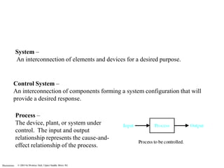
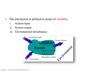
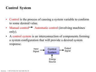
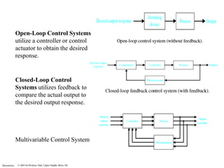
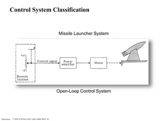
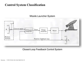
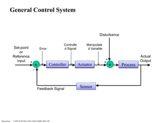
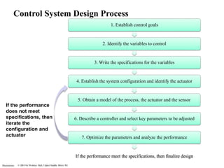
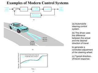
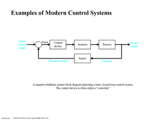


This document provides an overview of control systems. It defines a control system as an interconnection of components that provides a desired response. It discusses open and closed loop systems, control system classification, components, design process, examples, and the future of control systems. The document is being used to provide background on control principles and their engineering applications for a class.


