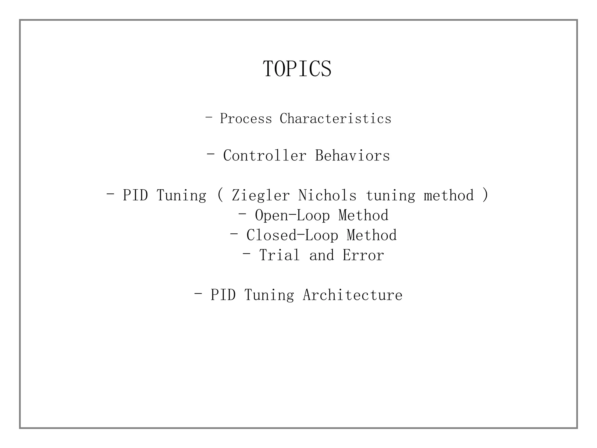
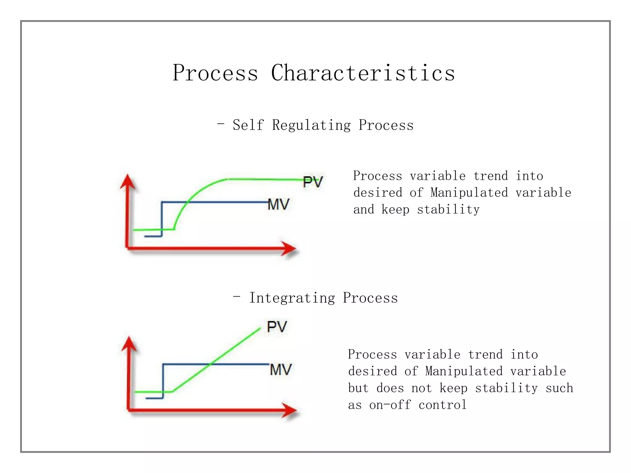
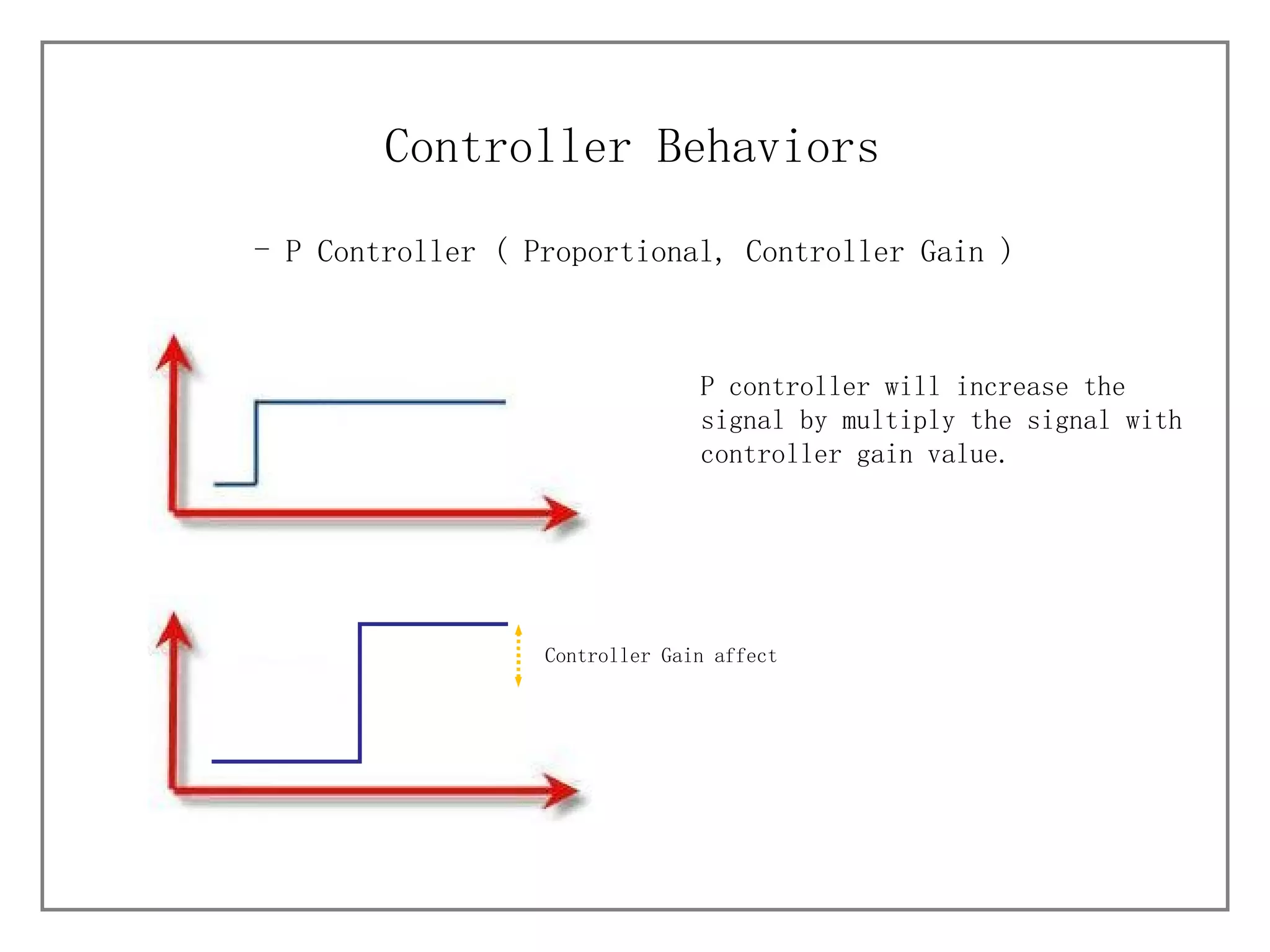
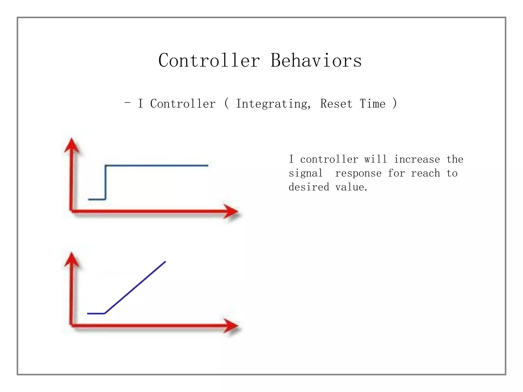
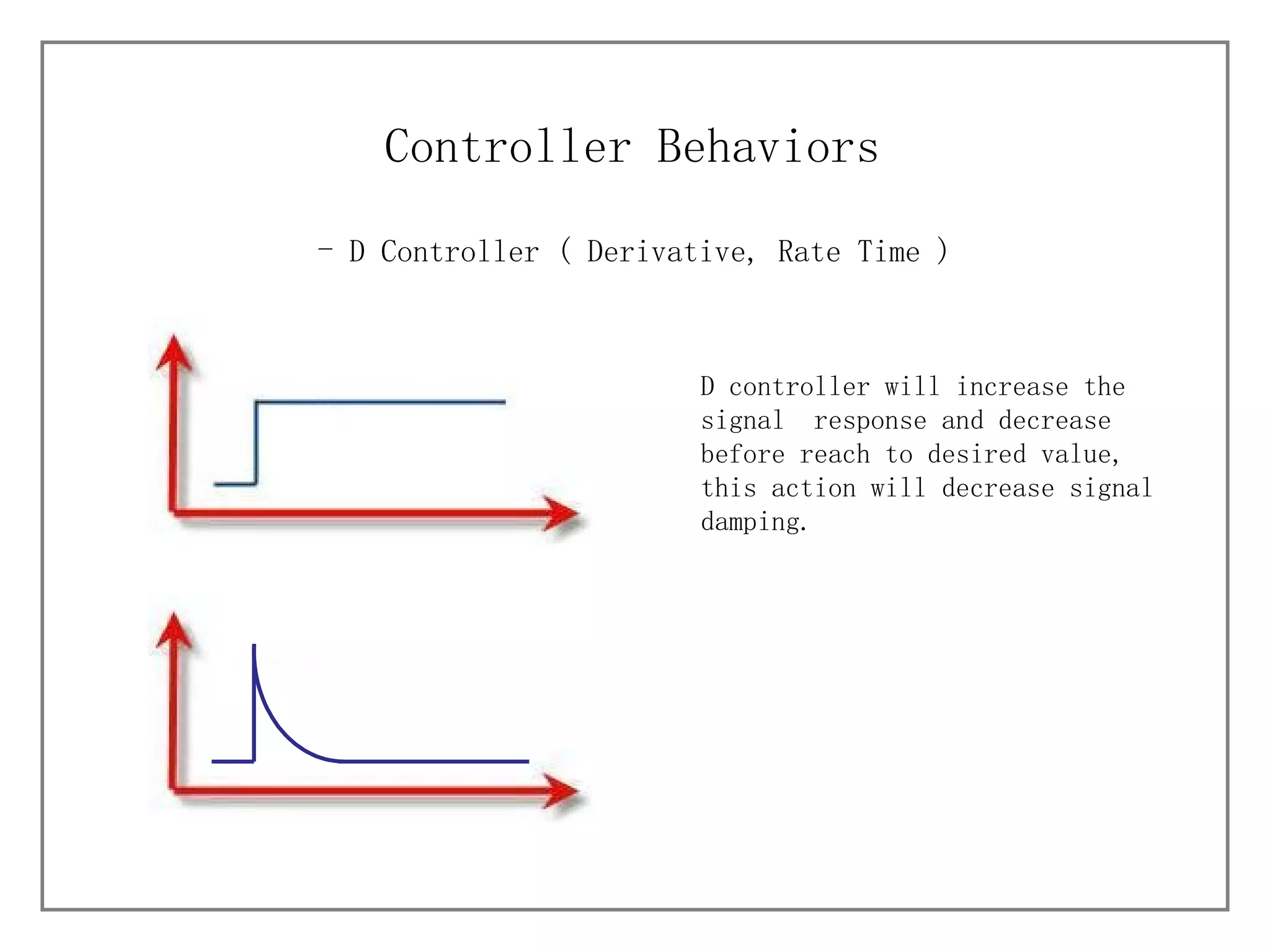
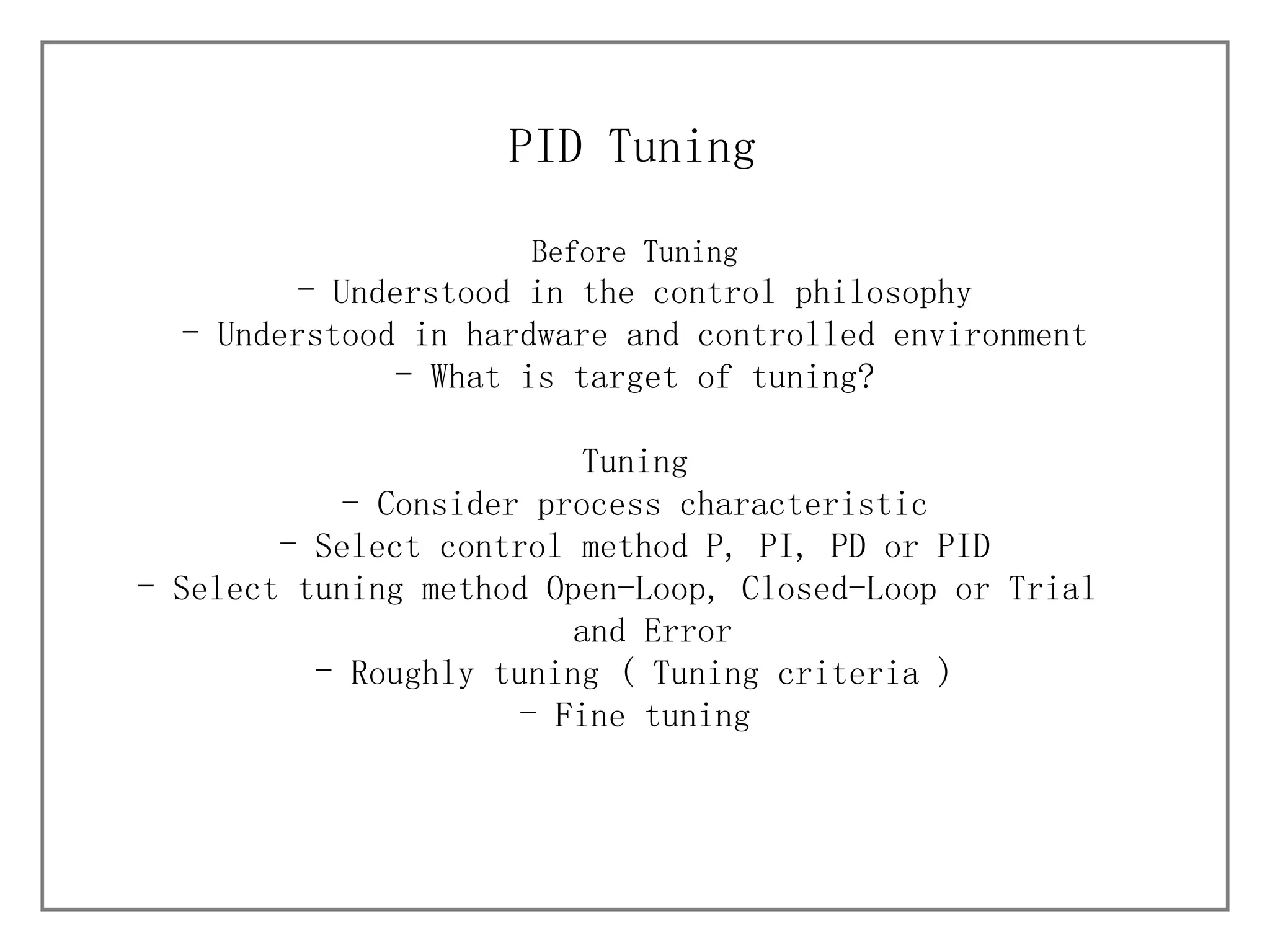
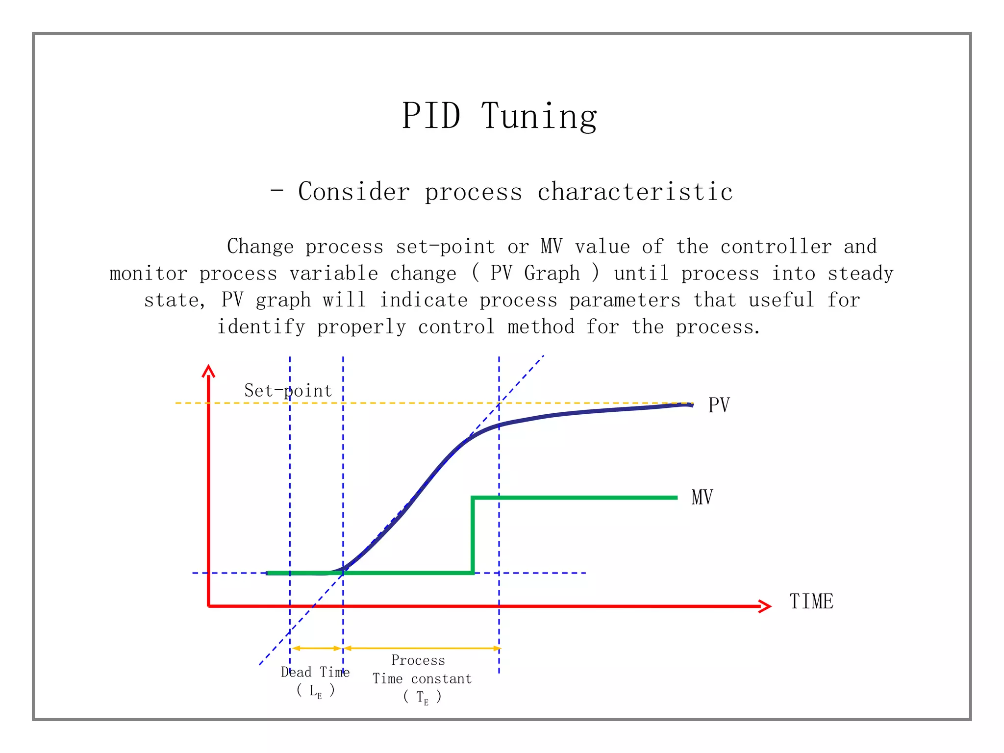
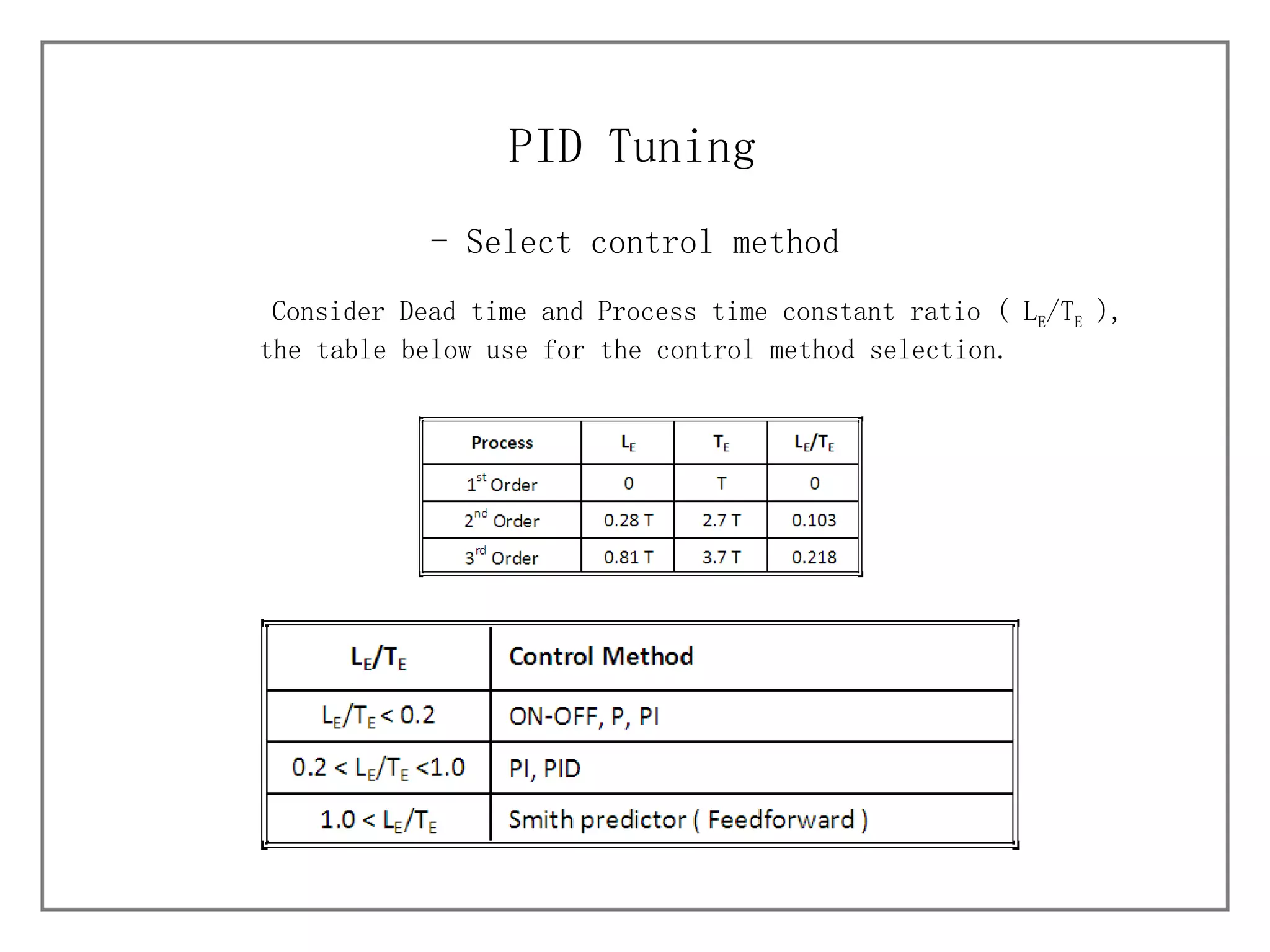
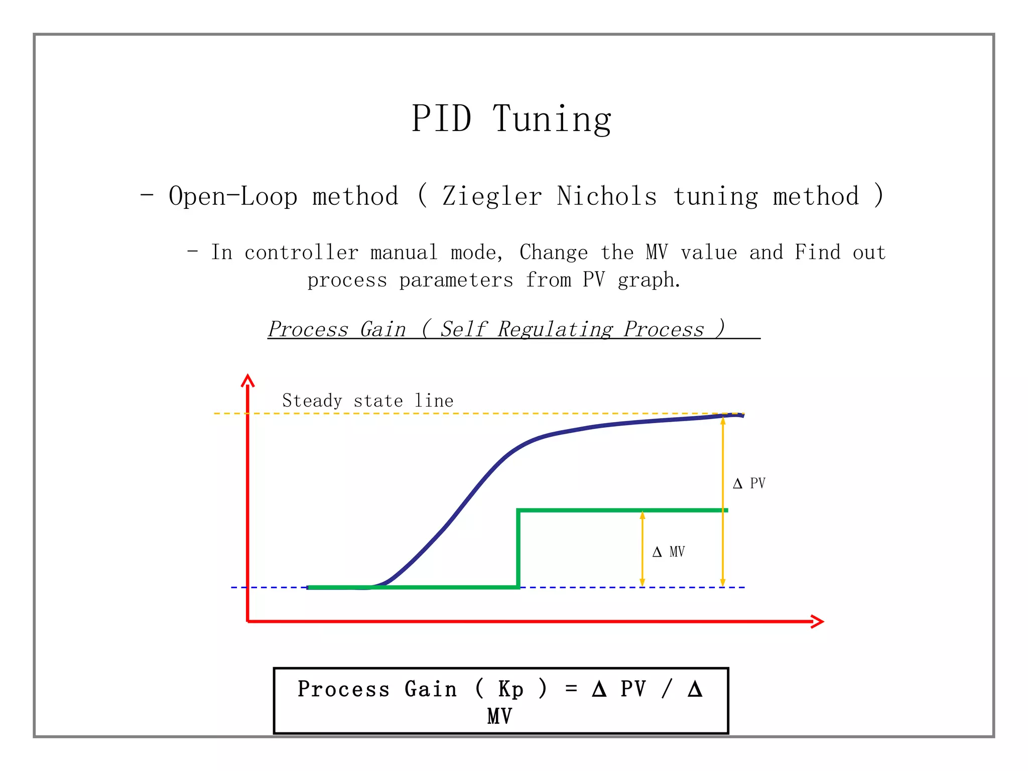
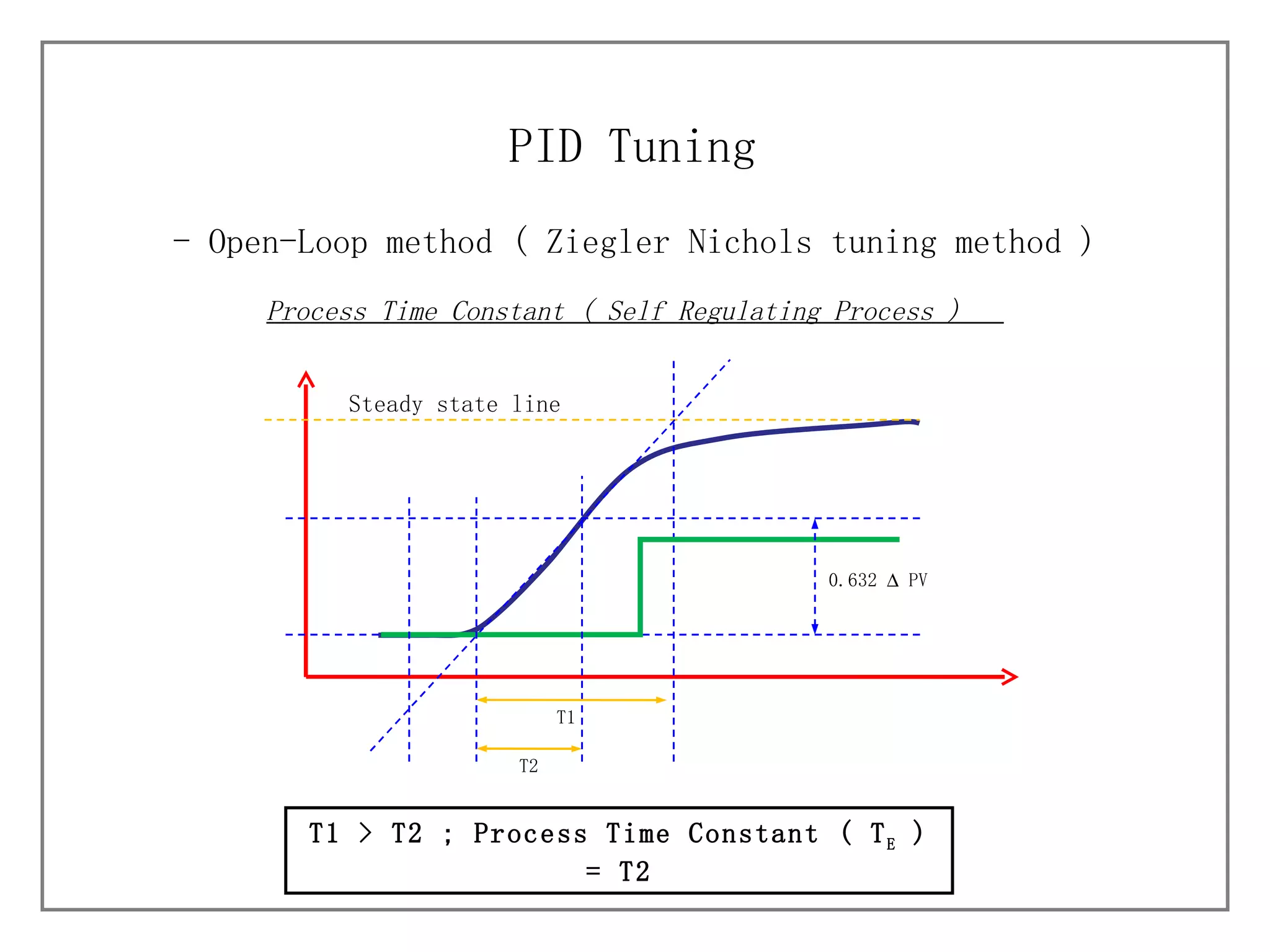
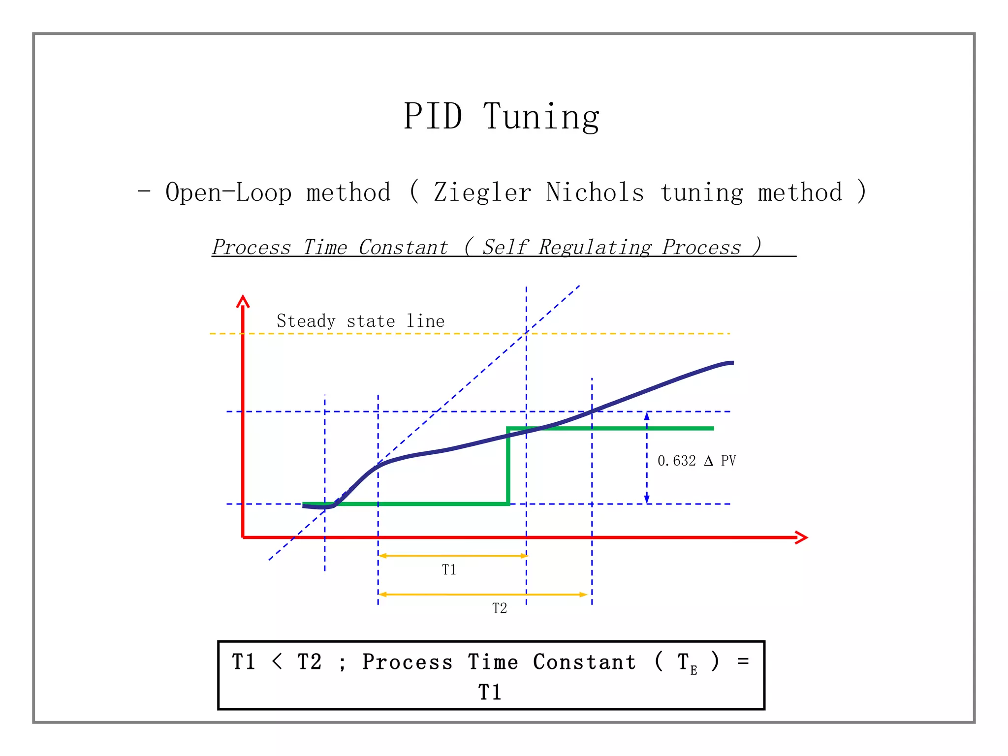
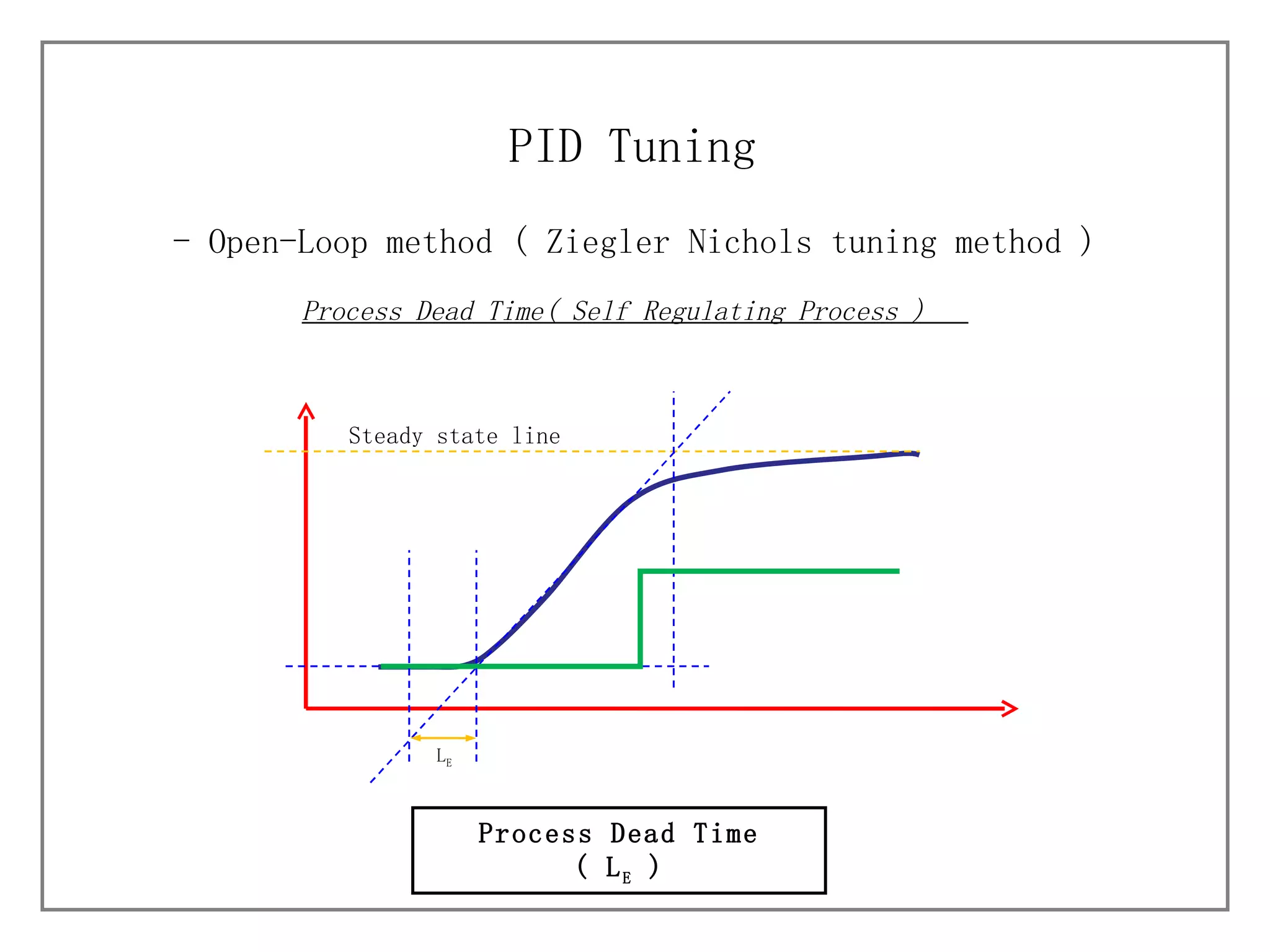
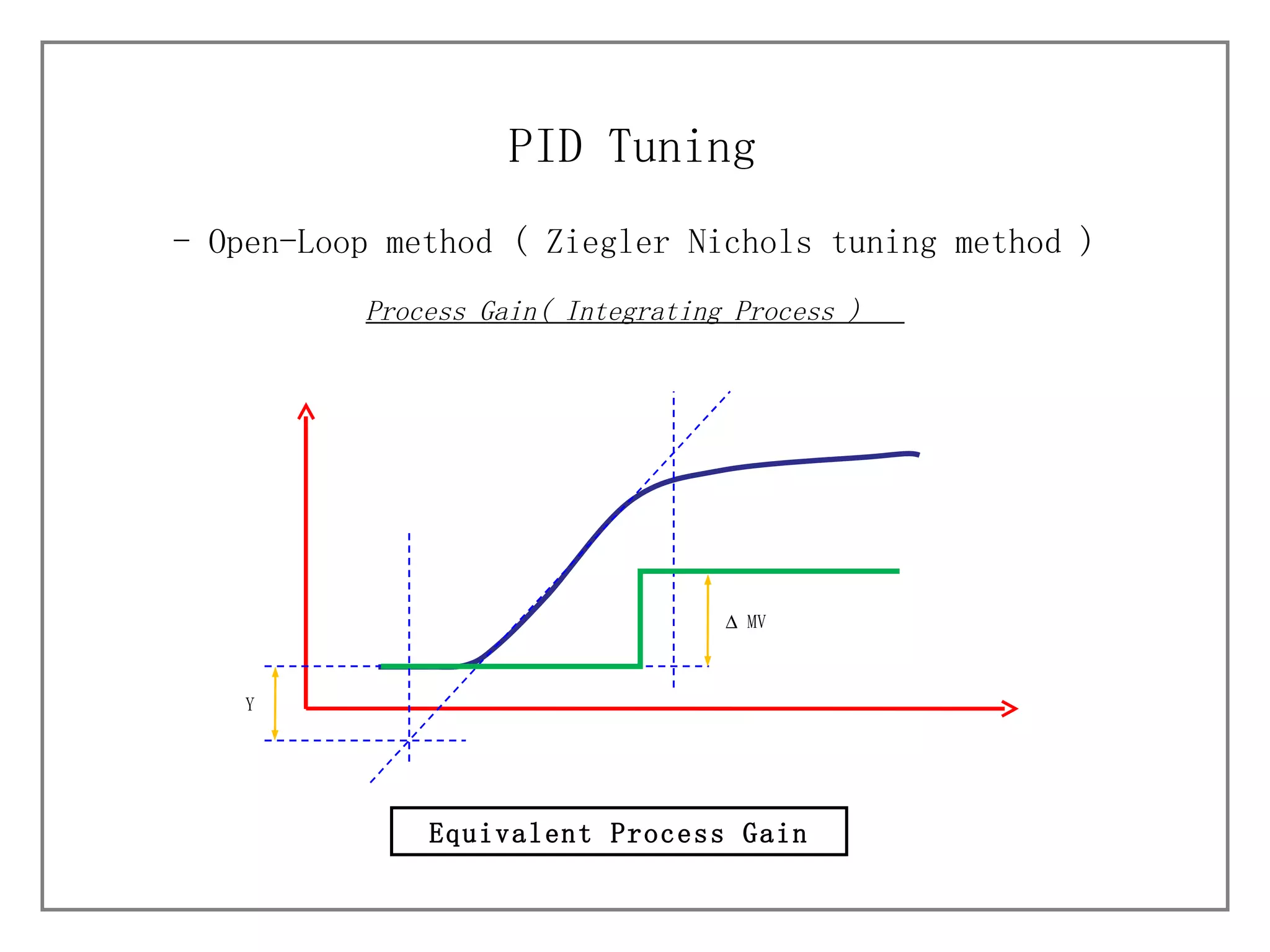
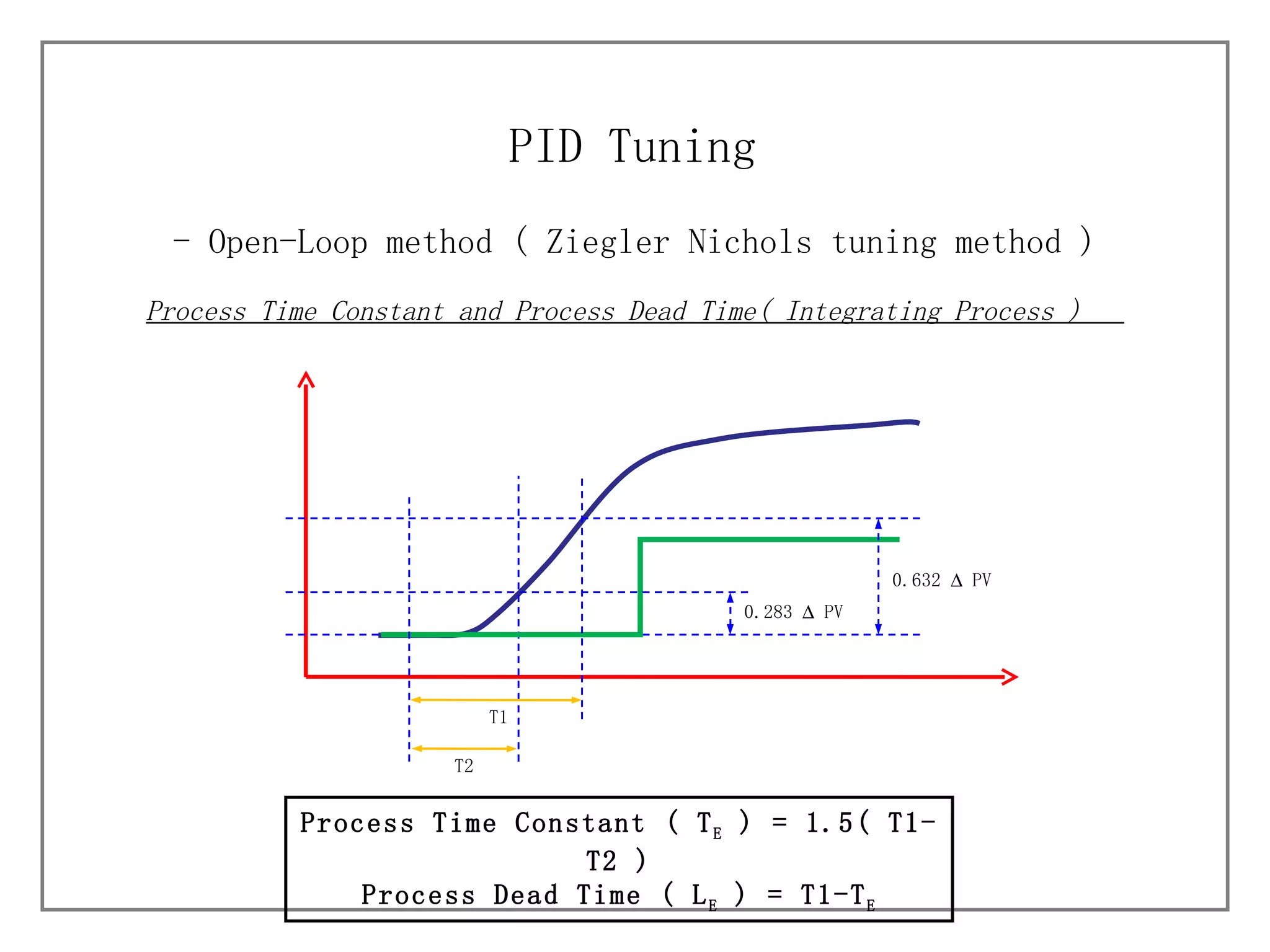
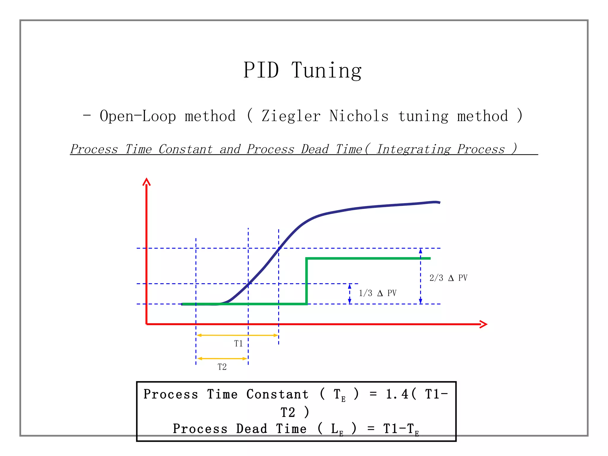
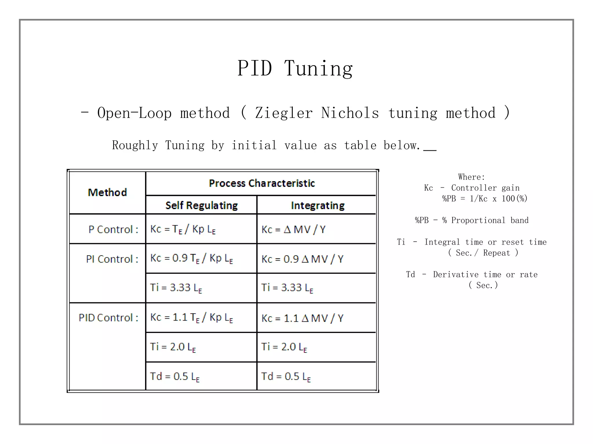
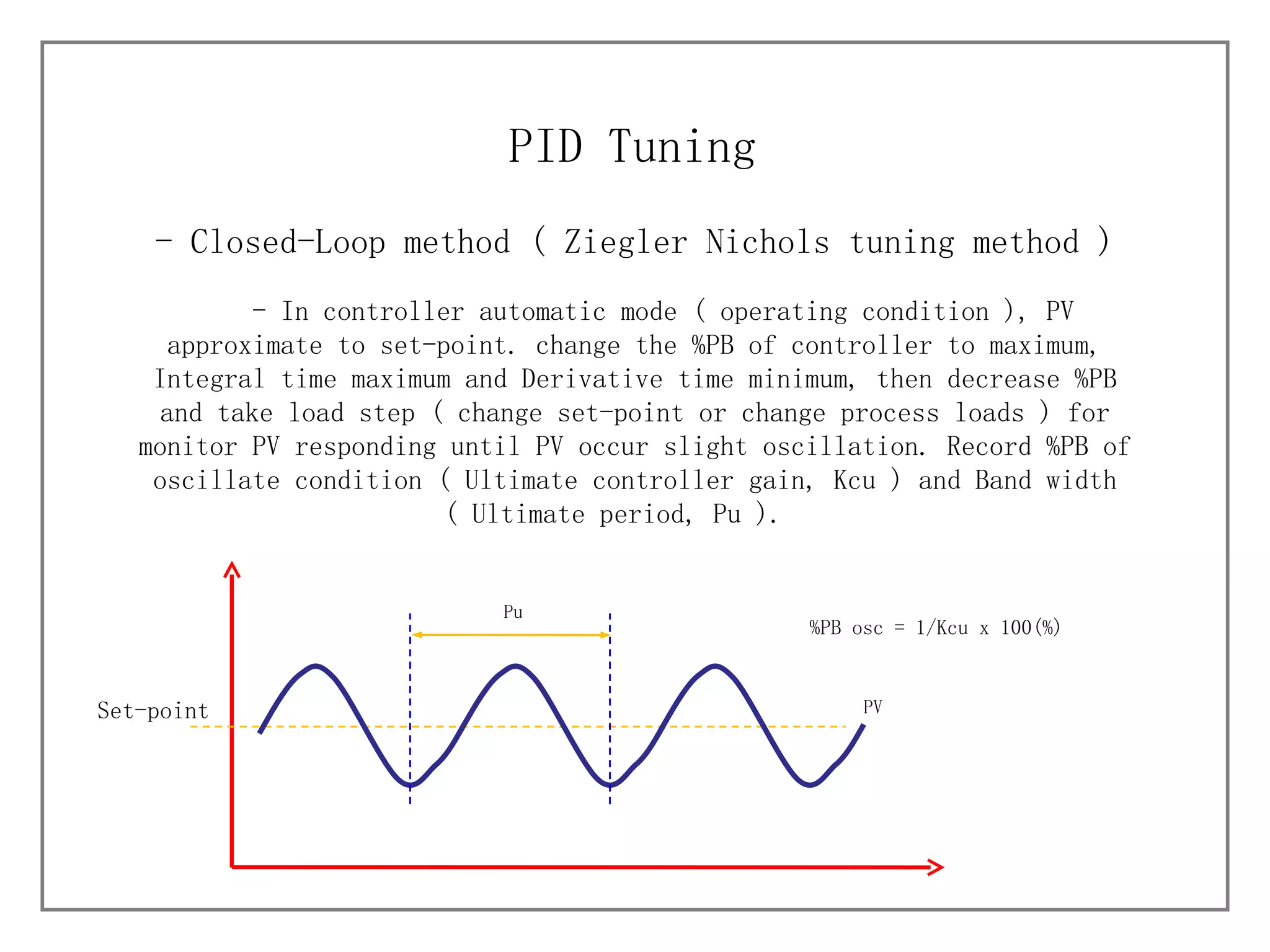
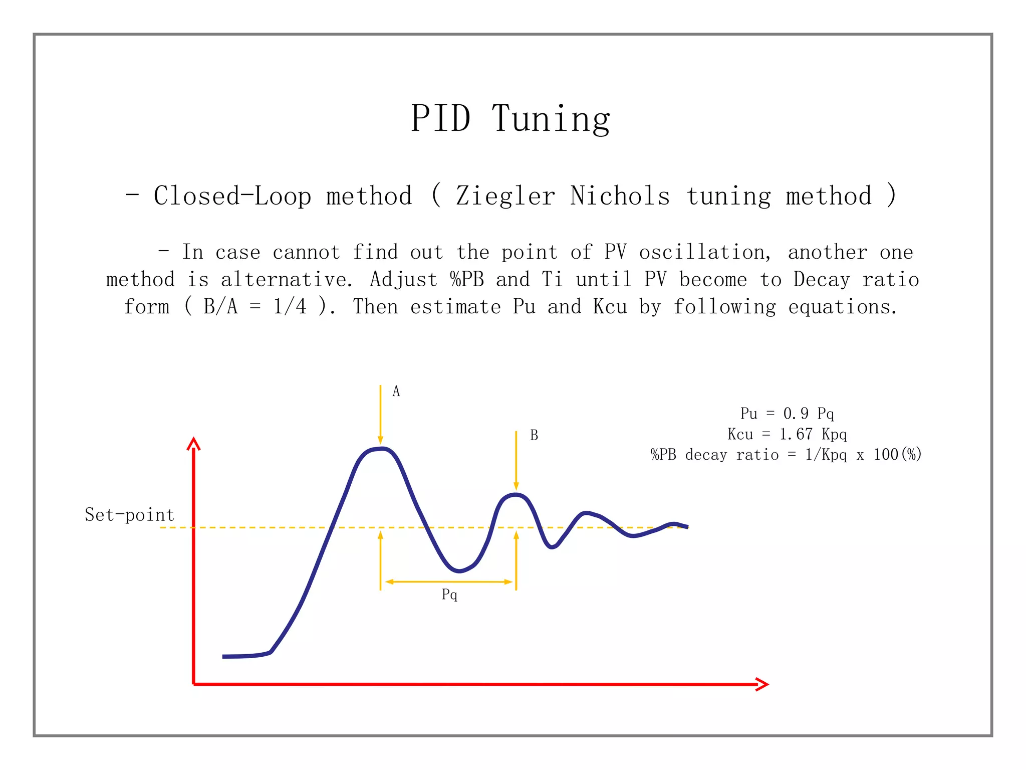
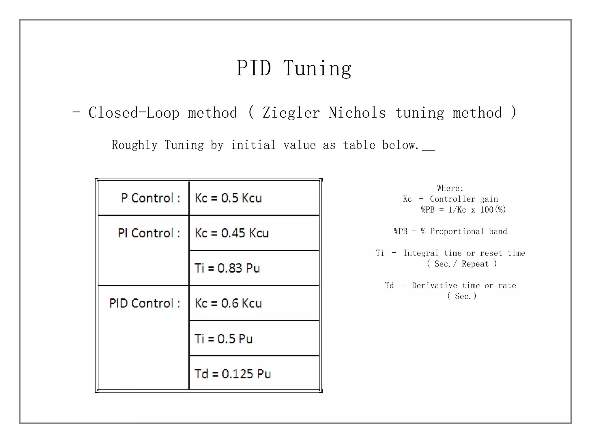
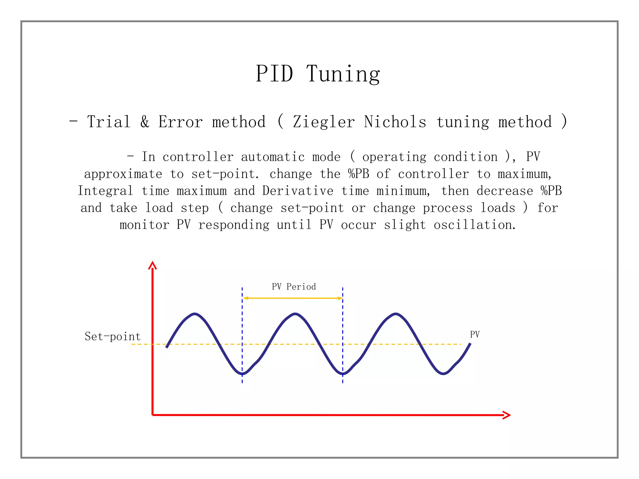
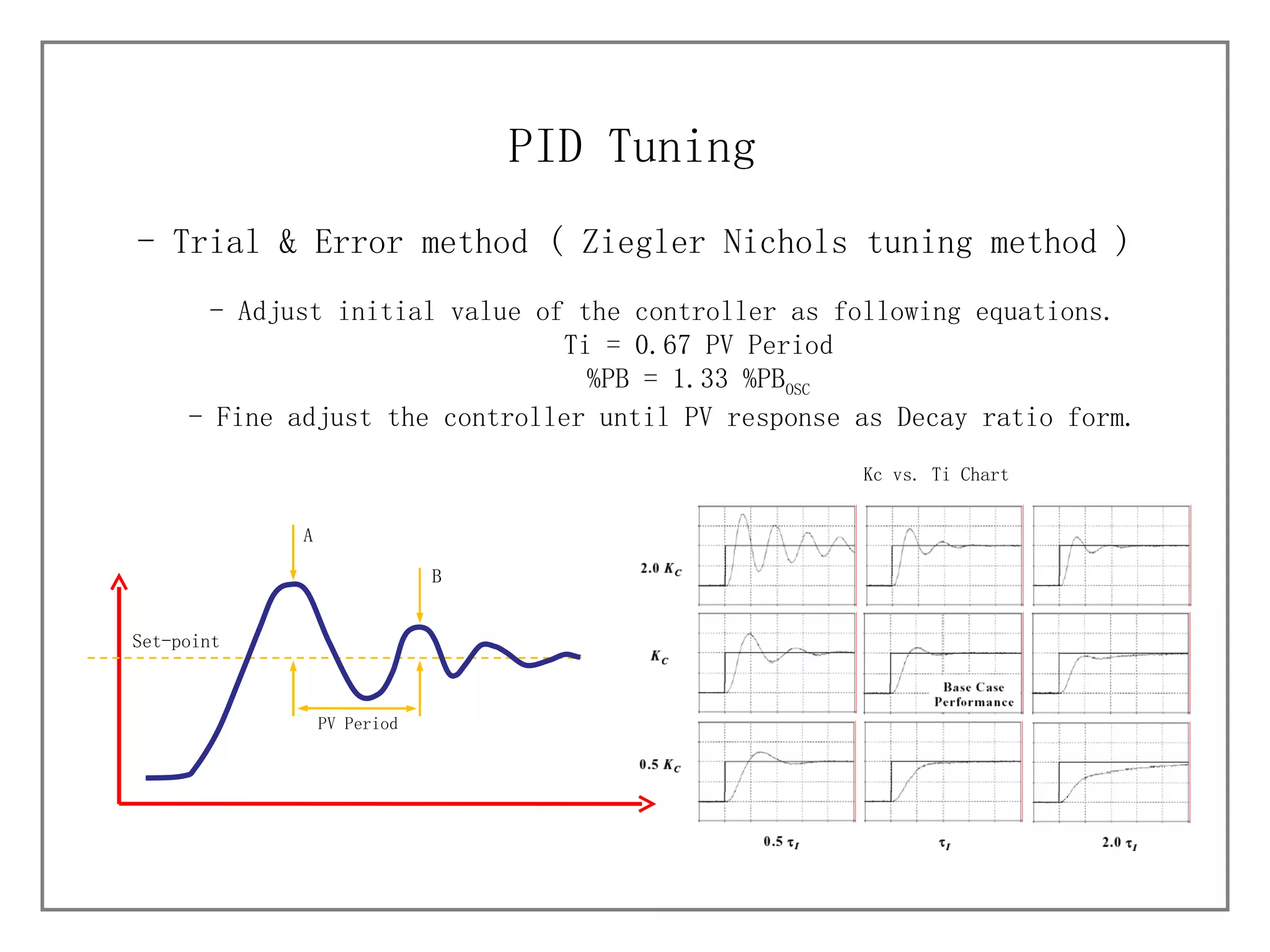
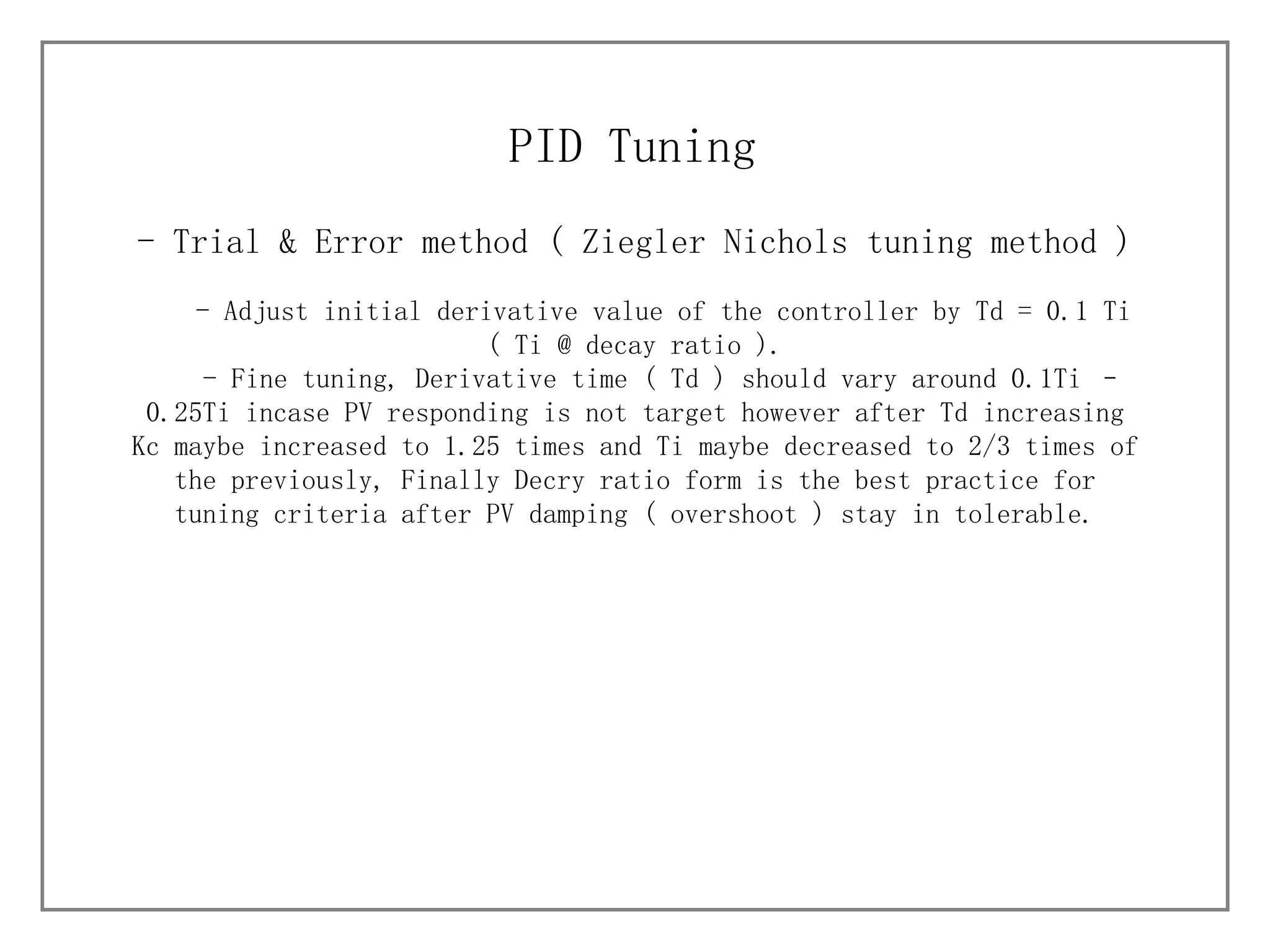
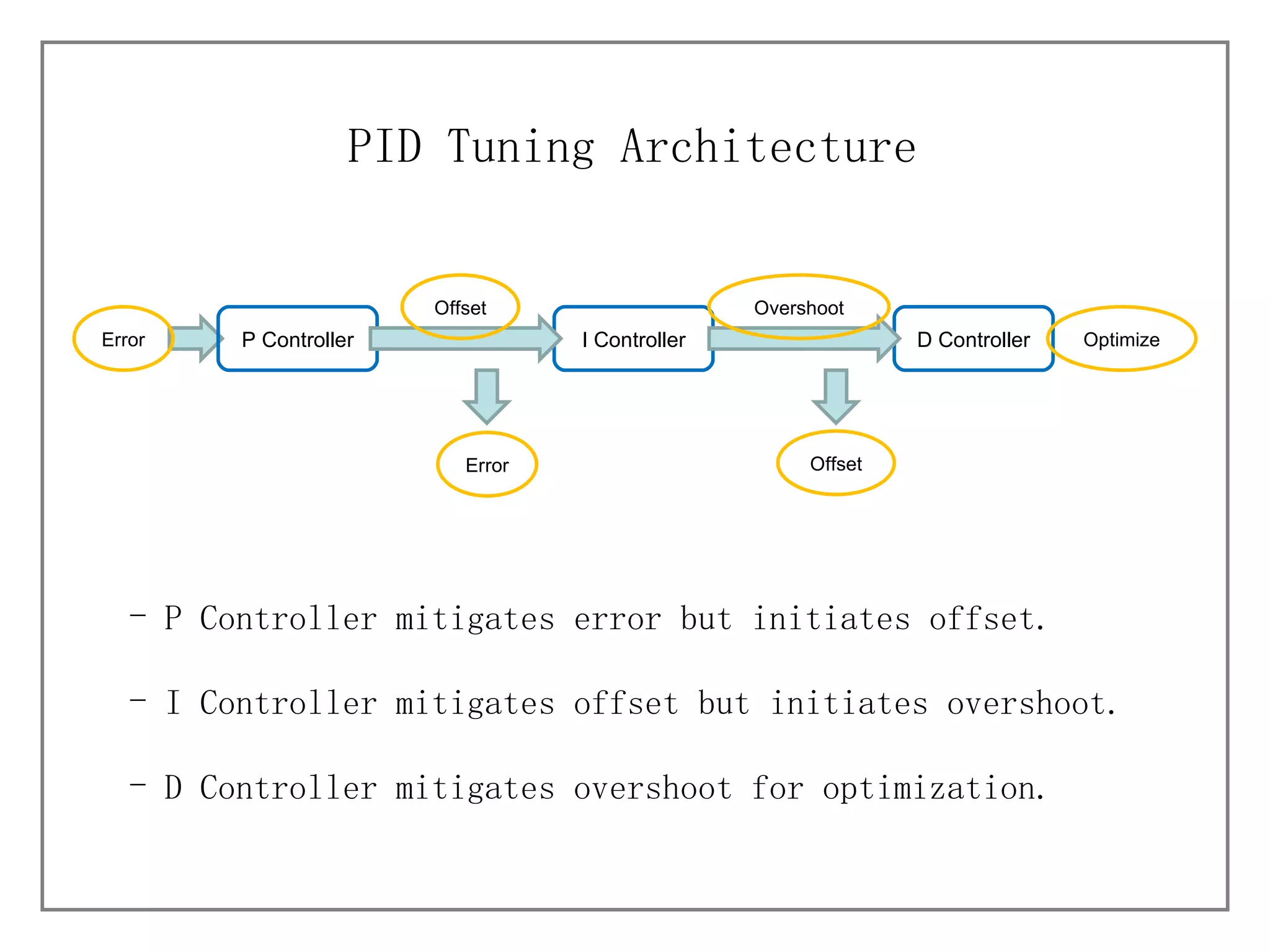
KNOWLEDGE MANAGEMENT PID Tuning BY JESSADA J.
Process Characteristics Controller Behaviors PID Tuning (  Ziegler Nichols tuning method ) Open-Loop Method Closed-Loop Method Trial and Error PID Tuning Architecture TOPICS
Self Regulating Process Process Characteristics Integrating Process Process variable trend into desired of Manipulated variable and keep stability  Process variable trend into desired of Manipulated variable but does not keep stability such as on-off control
P Controller ( Proportional, Controller Gain ) Controller Behaviors P controller will increase the signal by multiply the signal with controller gain value.  Controller Gain affect
I Controller ( Integrating, Reset Time ) Controller Behaviors I controller will increase the signal  response for reach to desired value.
D Controller ( Derivative, Rate Time ) Controller Behaviors D controller will increase the signal  response and decrease before reach to desired value, this action will decrease signal damping.
Before Tuning Understood in the control philosophy Understood in hardware and controlled environment What is target of tuning? Tuning - Consider process characteristic Select control method P, PI, PD or PID Select tuning method Open-Loop, Closed-Loop or Trial  and Error Roughly tuning ( Tuning criteria ) Fine tuning PID Tuning
- Consider process characteristic PID Tuning Change process set-point or MV value of the controller and monitor process variable change ( PV Graph ) until process into steady state, PV graph will indicate process parameters that useful for identify properly control method for the process.  PV TIME Set-point MV Process  Time constant ( T E  ) Dead Time ( L E  )
- Select control method PID Tuning Consider Dead time and Process time constant ratio ( L E /T E  ), the table below use for the control method selection.
- Select tuning method (  Ziegler Nichols tuning method ) PID Tuning Consider process conditions and select properly tuning method by consider limitation of each tuning methods as below. Open-loop method need to control the process loop in manual mode for change the MV value ( Control valve, Final element and etc. ). Closed-loop method is more difficultly than Open-loop method but takes advantage more as well, and has risk to equipments in loop damage cause process fluctuation, selected in case process cannot vary MV value. This method will make more advantage with integrating and runaway process. Trial and Error method need to control the process loop in manual mode like Open-loop method but the process parameters ( dead time, Time constant and process gain ) are not required,  this method need strongly understanding in PID tuning behaviors .
- Open-Loop method (  Ziegler Nichols tuning method ) PID Tuning - In controller manual mode, Change the MV value and Find out process parameters from PV graph.  Process Gain ( Kp ) =    PV /    MV Process Gain ( Self Regulating Process )  Steady state line    MV    PV
- Open-Loop method (  Ziegler Nichols tuning method ) PID Tuning T1 > T2 ; Process Time Constant ( T E  ) = T2 Process Time Constant ( Self Regulating Process )  Steady state line T2 0.632    PV  T1
- Open-Loop method (  Ziegler Nichols tuning method ) PID Tuning T1 < T2 ; Process Time Constant ( T E  ) = T1 Process Time Constant ( Self Regulating Process )  Steady state line T2 0.632    PV  T1
- Open-Loop method (  Ziegler Nichols tuning method ) PID Tuning Process Dead Time ( L E  ) Process Dead Time( Self Regulating Process )  Steady state line L E
- Open-Loop method (  Ziegler Nichols tuning method ) PID Tuning Equivalent Process Gain Process Gain( Integrating Process )  Y    MV
- Open-Loop method (  Ziegler Nichols tuning method ) PID Tuning Process Time Constant ( T E  ) = 1.5( T1-T2 ) Process Dead Time ( L E  ) = T1-T E T2 0.632    PV  T1 Process Time Constant and Process Dead Time( Integrating Process )  0.283    PV
- Open-Loop method (  Ziegler Nichols tuning method ) PID Tuning Process Time Constant ( T E  ) = 1.4( T1-T2 ) Process Dead Time ( L E  ) = T1-T E T2 2/3    PV  T1 Process Time Constant and Process Dead Time( Integrating Process )  1/3    PV
- Open-Loop method (  Ziegler Nichols tuning method ) PID Tuning Roughly Tuning by initial value as table below.   Where: Kc – Controller gain %PB = 1/Kc x 100(%) %PB - % Proportional band Ti – Integral time or reset time ( Sec./ Repeat ) Td – Derivative time or rate ( Sec.)
- Closed-Loop method (  Ziegler Nichols tuning method ) PID Tuning - In controller automatic mode ( operating condition ), PV approximate to set-point. change the %PB of controller to maximum, Integral time maximum and Derivative time minimum, then decrease %PB and take load step ( change set-point or change process loads ) for monitor PV responding until PV occur slight oscillation. Record %PB of oscillate condition ( Ultimate controller gain, Kcu ) and Band width ( Ultimate period, Pu ).  Set-point Pu PV %PB osc = 1/Kcu x 100(%)
- Closed-Loop method (  Ziegler Nichols tuning method ) PID Tuning - In case cannot find out the point of PV oscillation, another one method is alternative. Adjust %PB and Ti until PV become to Decay ratio form ( B/A = 1/4 ). Then estimate Pu and Kcu by following equations. Pu = 0.9 Pq Kcu = 1.67 Kpq %PB decay ratio = 1/Kpq x 100(%)  Set-point Pq A B
- Closed-Loop method (  Ziegler Nichols tuning method ) PID Tuning Roughly Tuning by initial value as table below.   Where: Kc – Controller gain %PB = 1/Kc x 100(%) %PB - % Proportional band Ti – Integral time or reset time ( Sec./ Repeat ) Td – Derivative time or rate ( Sec.)
- Trial & Error method (  Ziegler Nichols tuning method ) PID Tuning - In controller automatic mode ( operating condition ), PV approximate to set-point. change the %PB of controller to maximum, Integral time maximum and Derivative time minimum, then decrease %PB and take load step ( change set-point or change process loads ) for monitor PV responding until PV occur slight oscillation. Set-point PV Period PV
- Trial & Error method (  Ziegler Nichols tuning method ) PID Tuning - Adjust initial value of the controller as following equations. Ti = 0.67 PV Period %PB = 1.33 %PB OSC - Fine adjust the controller until PV response as Decay ratio form. Kc vs. Ti Chart Set-point PV Period A B
- Trial & Error method (  Ziegler Nichols tuning method ) PID Tuning - Adjust initial derivative value of the controller by Td = 0.1 Ti ( Ti @ decay ratio ). - Fine tuning, Derivative time ( Td ) should vary around 0.1Ti – 0.25Ti incase PV responding is not target however after Td increasing Kc maybe increased to 1.25 times and Ti maybe decreased to 2/3 times of the previously, Finally Decry ratio form is the best practice for tuning criteria after PV damping ( overshoot ) stay in tolerable.
P Controller mitigates error but initiates offset. I Controller mitigates offset but initiates overshoot. D Controller mitigates overshoot for optimization. PID Tuning Architecture Error P Controller I Controller D Controller Optimize Offset Error Overshoot Offset
THE END

PID Tuning

  • 1.
    KNOWLEDGE MANAGEMENT PIDTuning BY JESSADA J.
  • 2.
    Process Characteristics ControllerBehaviors PID Tuning ( Ziegler Nichols tuning method ) Open-Loop Method Closed-Loop Method Trial and Error PID Tuning Architecture TOPICS
  • 3.
    Self Regulating ProcessProcess Characteristics Integrating Process Process variable trend into desired of Manipulated variable and keep stability Process variable trend into desired of Manipulated variable but does not keep stability such as on-off control
  • 4.
    P Controller (Proportional, Controller Gain ) Controller Behaviors P controller will increase the signal by multiply the signal with controller gain value. Controller Gain affect
  • 5.
    I Controller (Integrating, Reset Time ) Controller Behaviors I controller will increase the signal response for reach to desired value.
  • 6.
    D Controller (Derivative, Rate Time ) Controller Behaviors D controller will increase the signal response and decrease before reach to desired value, this action will decrease signal damping.
  • 7.
    Before Tuning Understoodin the control philosophy Understood in hardware and controlled environment What is target of tuning? Tuning - Consider process characteristic Select control method P, PI, PD or PID Select tuning method Open-Loop, Closed-Loop or Trial and Error Roughly tuning ( Tuning criteria ) Fine tuning PID Tuning
  • 8.
    - Consider processcharacteristic PID Tuning Change process set-point or MV value of the controller and monitor process variable change ( PV Graph ) until process into steady state, PV graph will indicate process parameters that useful for identify properly control method for the process. PV TIME Set-point MV Process Time constant ( T E ) Dead Time ( L E )
  • 9.
    - Select controlmethod PID Tuning Consider Dead time and Process time constant ratio ( L E /T E ), the table below use for the control method selection.
  • 10.
    - Select tuningmethod ( Ziegler Nichols tuning method ) PID Tuning Consider process conditions and select properly tuning method by consider limitation of each tuning methods as below. Open-loop method need to control the process loop in manual mode for change the MV value ( Control valve, Final element and etc. ). Closed-loop method is more difficultly than Open-loop method but takes advantage more as well, and has risk to equipments in loop damage cause process fluctuation, selected in case process cannot vary MV value. This method will make more advantage with integrating and runaway process. Trial and Error method need to control the process loop in manual mode like Open-loop method but the process parameters ( dead time, Time constant and process gain ) are not required, this method need strongly understanding in PID tuning behaviors .
  • 11.
    - Open-Loop method( Ziegler Nichols tuning method ) PID Tuning - In controller manual mode, Change the MV value and Find out process parameters from PV graph. Process Gain ( Kp ) =  PV /  MV Process Gain ( Self Regulating Process ) Steady state line  MV  PV
  • 12.
    - Open-Loop method( Ziegler Nichols tuning method ) PID Tuning T1 > T2 ; Process Time Constant ( T E ) = T2 Process Time Constant ( Self Regulating Process ) Steady state line T2 0.632  PV T1
  • 13.
    - Open-Loop method( Ziegler Nichols tuning method ) PID Tuning T1 < T2 ; Process Time Constant ( T E ) = T1 Process Time Constant ( Self Regulating Process ) Steady state line T2 0.632  PV T1
  • 14.
    - Open-Loop method( Ziegler Nichols tuning method ) PID Tuning Process Dead Time ( L E ) Process Dead Time( Self Regulating Process ) Steady state line L E
  • 15.
    - Open-Loop method( Ziegler Nichols tuning method ) PID Tuning Equivalent Process Gain Process Gain( Integrating Process ) Y  MV
  • 16.
    - Open-Loop method( Ziegler Nichols tuning method ) PID Tuning Process Time Constant ( T E ) = 1.5( T1-T2 ) Process Dead Time ( L E ) = T1-T E T2 0.632  PV T1 Process Time Constant and Process Dead Time( Integrating Process ) 0.283  PV
  • 17.
    - Open-Loop method( Ziegler Nichols tuning method ) PID Tuning Process Time Constant ( T E ) = 1.4( T1-T2 ) Process Dead Time ( L E ) = T1-T E T2 2/3  PV T1 Process Time Constant and Process Dead Time( Integrating Process ) 1/3  PV
  • 18.
    - Open-Loop method( Ziegler Nichols tuning method ) PID Tuning Roughly Tuning by initial value as table below. Where: Kc – Controller gain %PB = 1/Kc x 100(%) %PB - % Proportional band Ti – Integral time or reset time ( Sec./ Repeat ) Td – Derivative time or rate ( Sec.)
  • 19.
    - Closed-Loop method( Ziegler Nichols tuning method ) PID Tuning - In controller automatic mode ( operating condition ), PV approximate to set-point. change the %PB of controller to maximum, Integral time maximum and Derivative time minimum, then decrease %PB and take load step ( change set-point or change process loads ) for monitor PV responding until PV occur slight oscillation. Record %PB of oscillate condition ( Ultimate controller gain, Kcu ) and Band width ( Ultimate period, Pu ). Set-point Pu PV %PB osc = 1/Kcu x 100(%)
  • 20.
    - Closed-Loop method( Ziegler Nichols tuning method ) PID Tuning - In case cannot find out the point of PV oscillation, another one method is alternative. Adjust %PB and Ti until PV become to Decay ratio form ( B/A = 1/4 ). Then estimate Pu and Kcu by following equations. Pu = 0.9 Pq Kcu = 1.67 Kpq %PB decay ratio = 1/Kpq x 100(%) Set-point Pq A B
  • 21.
    - Closed-Loop method( Ziegler Nichols tuning method ) PID Tuning Roughly Tuning by initial value as table below. Where: Kc – Controller gain %PB = 1/Kc x 100(%) %PB - % Proportional band Ti – Integral time or reset time ( Sec./ Repeat ) Td – Derivative time or rate ( Sec.)
  • 22.
    - Trial &Error method ( Ziegler Nichols tuning method ) PID Tuning - In controller automatic mode ( operating condition ), PV approximate to set-point. change the %PB of controller to maximum, Integral time maximum and Derivative time minimum, then decrease %PB and take load step ( change set-point or change process loads ) for monitor PV responding until PV occur slight oscillation. Set-point PV Period PV
  • 23.
    - Trial &Error method ( Ziegler Nichols tuning method ) PID Tuning - Adjust initial value of the controller as following equations. Ti = 0.67 PV Period %PB = 1.33 %PB OSC - Fine adjust the controller until PV response as Decay ratio form. Kc vs. Ti Chart Set-point PV Period A B
  • 24.
    - Trial &Error method ( Ziegler Nichols tuning method ) PID Tuning - Adjust initial derivative value of the controller by Td = 0.1 Ti ( Ti @ decay ratio ). - Fine tuning, Derivative time ( Td ) should vary around 0.1Ti – 0.25Ti incase PV responding is not target however after Td increasing Kc maybe increased to 1.25 times and Ti maybe decreased to 2/3 times of the previously, Finally Decry ratio form is the best practice for tuning criteria after PV damping ( overshoot ) stay in tolerable.
  • 25.
    P Controller mitigateserror but initiates offset. I Controller mitigates offset but initiates overshoot. D Controller mitigates overshoot for optimization. PID Tuning Architecture Error P Controller I Controller D Controller Optimize Offset Error Overshoot Offset
  • 26.