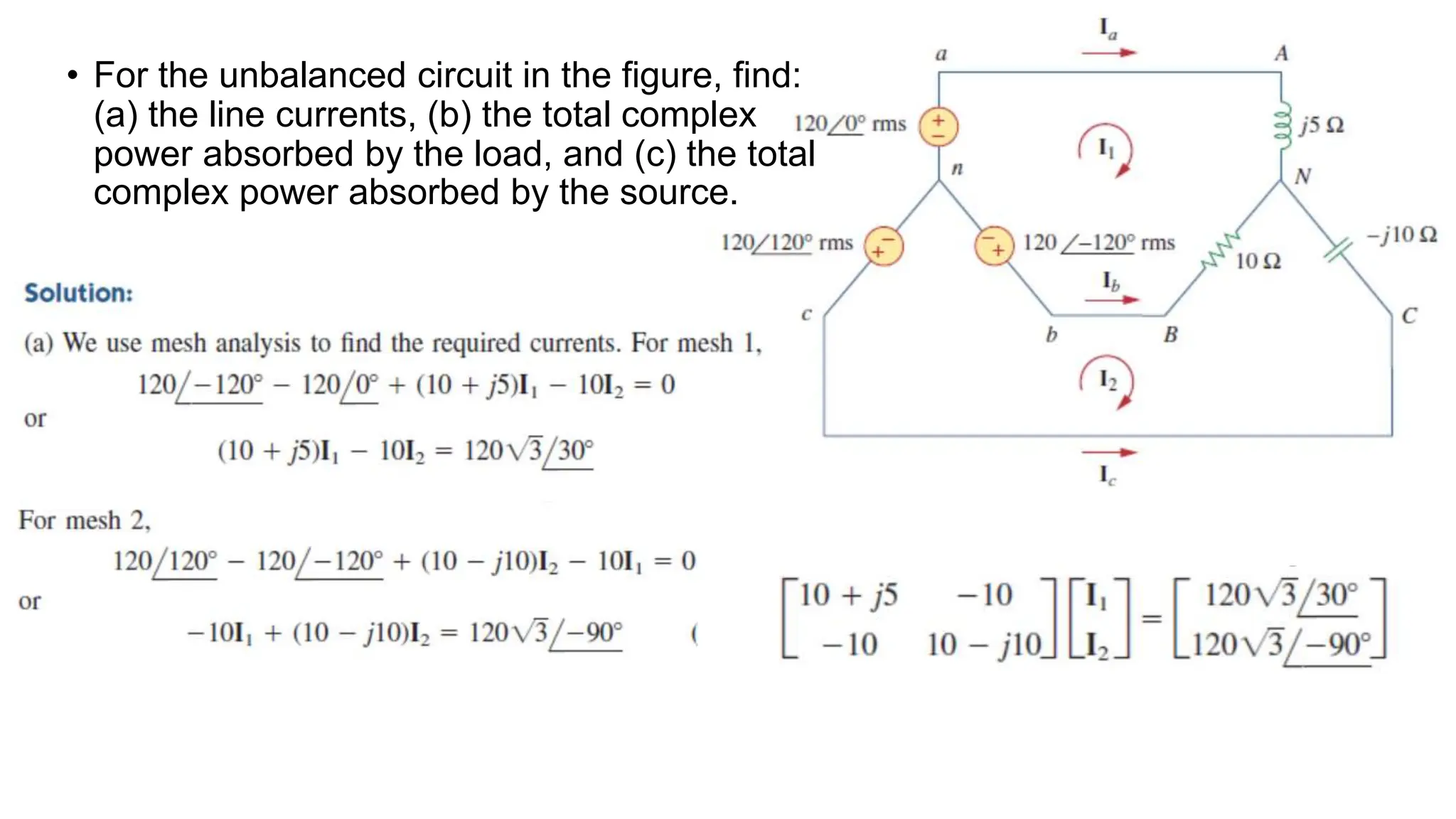
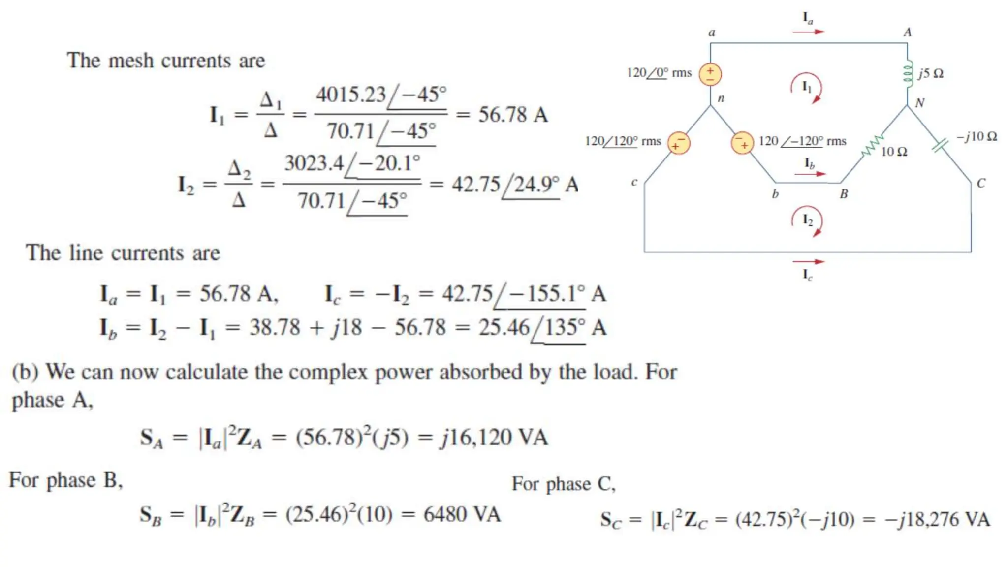
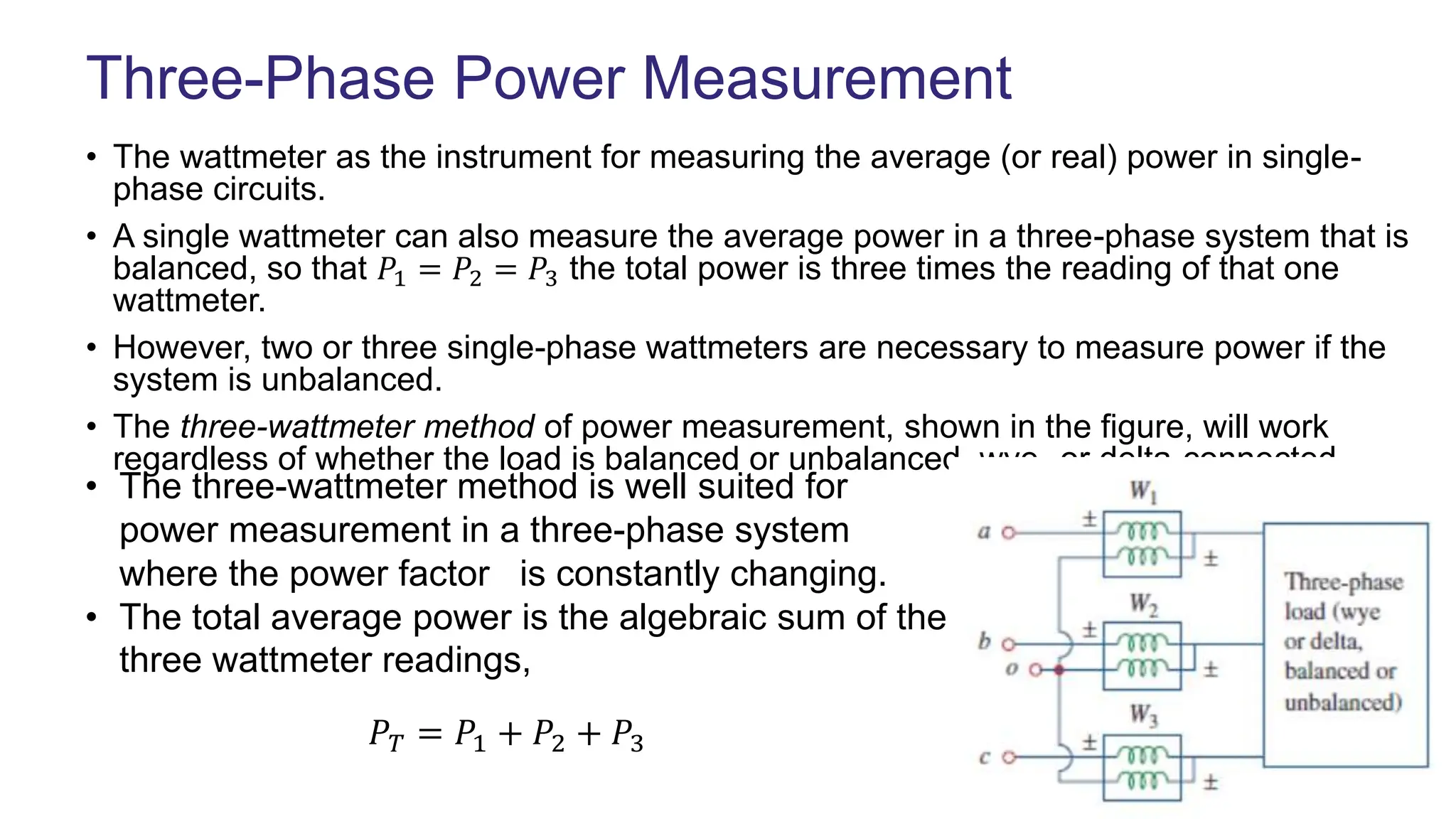
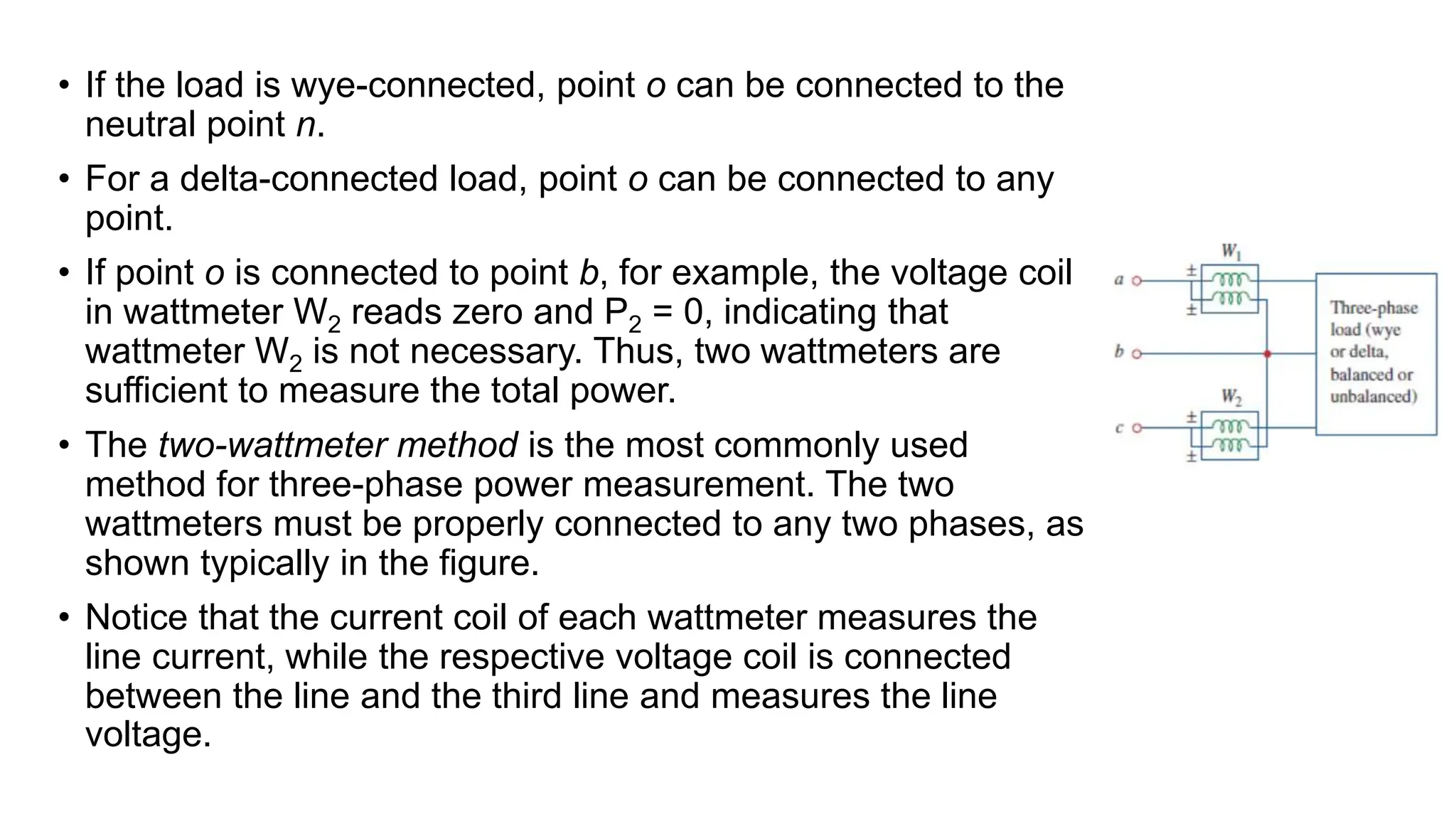
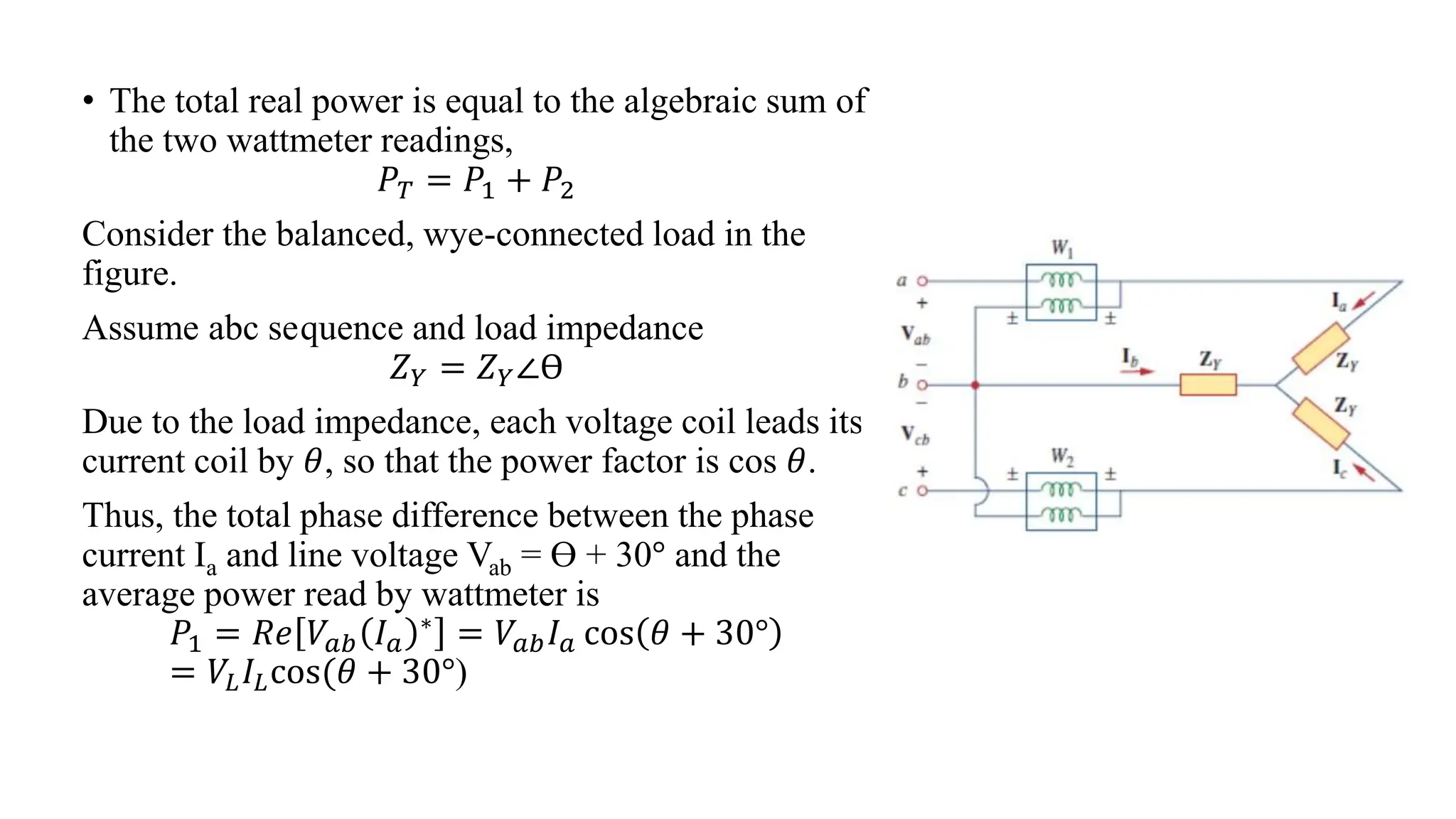
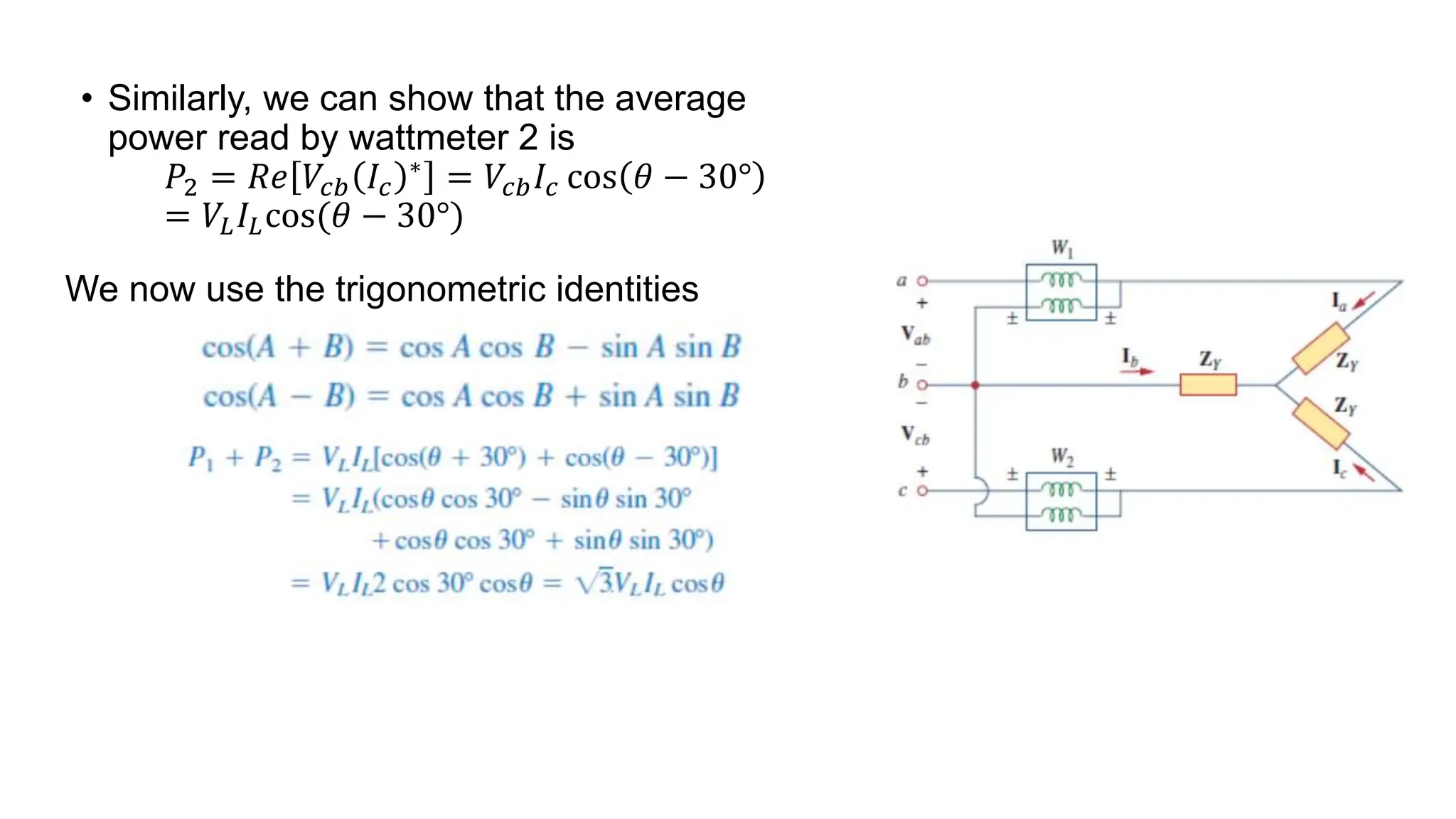
Unbalanced Three Phase
System
Unbalanced System
• An unbalanced system is caused by two possible situations: (1) The
source voltages are not equal in magnitude and/or differ in phase by
angles that are unequal, or (2) load impedances are unequal. Thus,
• An unbalanced system is due to unbalanced voltage sources or an
unbalanced load.
• To simplify analysis, we will assume balanced source voltages, but an
unbalanced load.
• Unbalanced three-phase systems are solved by direct application of
mesh and nodal analysis.
Unbalanced Load
• The figure shows an example of an
unbalanced three-phase system that
consists of balanced source voltages (not
shown in the figure) and an unbalanced
Y-connected load (shown in the figure).
Since the load is unbalanced, ZA, ZB
anda ZC are not equal. The line currents
are determined by Ohm’s law as
• This set of unbalanced line currents produces current in the
neutral line, which is not zero as in a balanced system. Applying
KCL at node N gives the neutral line current as
• The unbalanced Y-load of the figure has balanced voltages of 100 V and
the acb sequence. Calculate the line currents and the neutral current. Take
ZA = 15 ohms, ZB = 10 + j5 ohms, ZC = 6 – j8 ohms.
• Solution:
The line currents are
The current in the neutral line is
• The unbalanced △-load of the figure is supplied by balanced
line-to-line voltages of 440 V in the positive sequence. Find the
line currents. Take Vab as reference.
• For the unbalanced circuit in the figure, find:
(a) the line currents, (b) the total complex
power absorbed by the load, and (c) the total
complex power absorbed by the source.
• Find the line currents in the unbalanced three-phase circuit of
the figure and the real power absorbed by the load.
Applications
Three-Phase Power Measurement
• The wattmeter as the instrument for measuring the average (or real) power in single-
phase circuits.
• A single wattmeter can also measure the average power in a three-phase system that is
balanced, so that 𝑃1 = 𝑃2 = 𝑃3 the total power is three times the reading of that one
wattmeter.
• However, two or three single-phase wattmeters are necessary to measure power if the
system is unbalanced.
• The three-wattmeter method of power measurement, shown in the figure, will work
regardless of whether the load is balanced or unbalanced, wye- or delta-connected.
𝑃𝑇 = 𝑃1 + 𝑃2 + 𝑃3
• The three-wattmeter method is well suited for
power measurement in a three-phase system
where the power factor is constantly changing.
• The total average power is the algebraic sum of the
three wattmeter readings,
• If the load is wye-connected, point o can be connected to the
neutral point n.
• For a delta-connected load, point o can be connected to any
point.
• If point o is connected to point b, for example, the voltage coil
in wattmeter W2 reads zero and P2 = 0, indicating that
wattmeter W2 is not necessary. Thus, two wattmeters are
sufficient to measure the total power.
• The two-wattmeter method is the most commonly used
method for three-phase power measurement. The two
wattmeters must be properly connected to any two phases, as
shown typically in the figure.
• Notice that the current coil of each wattmeter measures the
line current, while the respective voltage coil is connected
between the line and the third line and measures the line
voltage.
• The total real power is equal to the algebraic sum of
the two wattmeter readings,
𝑃𝑇 = 𝑃1 + 𝑃2
Consider the balanced, wye-connected load in the
figure.
Assume abc sequence and load impedance
𝑍𝑌 = 𝑍𝑌∠ϴ
Due to the load impedance, each voltage coil leads its
current coil by 𝜃, so that the power factor is cos 𝜃.
Thus, the total phase difference between the phase
current Ia and line voltage Vab = ϴ + 30° and the
average power read by wattmeter is
𝑃1 = 𝑅𝑒 𝑉𝑎𝑏 𝐼𝑎
∗ = 𝑉𝑎𝑏𝐼𝑎 cos 𝜃 + 30°
= 𝑉𝐿𝐼𝐿cos(𝜃 + 30°)
• Similarly, we can show that the average
power read by wattmeter 2 is
𝑃2 = 𝑅𝑒 𝑉𝑐𝑏 𝐼𝑐
∗ = 𝑉𝑐𝑏𝐼𝑐 cos 𝜃 − 30°
= 𝑉𝐿𝐼𝐿cos(𝜃 − 30°)
We now use the trigonometric identities

Unbalanced Three Phase Systems and circuits.pptx

  • 1.
  • 2.
    Unbalanced System • Anunbalanced system is caused by two possible situations: (1) The source voltages are not equal in magnitude and/or differ in phase by angles that are unequal, or (2) load impedances are unequal. Thus, • An unbalanced system is due to unbalanced voltage sources or an unbalanced load. • To simplify analysis, we will assume balanced source voltages, but an unbalanced load. • Unbalanced three-phase systems are solved by direct application of mesh and nodal analysis.
  • 3.
    Unbalanced Load • Thefigure shows an example of an unbalanced three-phase system that consists of balanced source voltages (not shown in the figure) and an unbalanced Y-connected load (shown in the figure). Since the load is unbalanced, ZA, ZB anda ZC are not equal. The line currents are determined by Ohm’s law as
  • 4.
    • This setof unbalanced line currents produces current in the neutral line, which is not zero as in a balanced system. Applying KCL at node N gives the neutral line current as
  • 5.
    • The unbalancedY-load of the figure has balanced voltages of 100 V and the acb sequence. Calculate the line currents and the neutral current. Take ZA = 15 ohms, ZB = 10 + j5 ohms, ZC = 6 – j8 ohms. • Solution: The line currents are The current in the neutral line is
  • 6.
    • The unbalanced△-load of the figure is supplied by balanced line-to-line voltages of 440 V in the positive sequence. Find the line currents. Take Vab as reference.
  • 7.
    • For theunbalanced circuit in the figure, find: (a) the line currents, (b) the total complex power absorbed by the load, and (c) the total complex power absorbed by the source.
  • 11.
    • Find theline currents in the unbalanced three-phase circuit of the figure and the real power absorbed by the load.
  • 12.
  • 13.
    Three-Phase Power Measurement •The wattmeter as the instrument for measuring the average (or real) power in single- phase circuits. • A single wattmeter can also measure the average power in a three-phase system that is balanced, so that 𝑃1 = 𝑃2 = 𝑃3 the total power is three times the reading of that one wattmeter. • However, two or three single-phase wattmeters are necessary to measure power if the system is unbalanced. • The three-wattmeter method of power measurement, shown in the figure, will work regardless of whether the load is balanced or unbalanced, wye- or delta-connected. 𝑃𝑇 = 𝑃1 + 𝑃2 + 𝑃3 • The three-wattmeter method is well suited for power measurement in a three-phase system where the power factor is constantly changing. • The total average power is the algebraic sum of the three wattmeter readings,
  • 14.
    • If theload is wye-connected, point o can be connected to the neutral point n. • For a delta-connected load, point o can be connected to any point. • If point o is connected to point b, for example, the voltage coil in wattmeter W2 reads zero and P2 = 0, indicating that wattmeter W2 is not necessary. Thus, two wattmeters are sufficient to measure the total power. • The two-wattmeter method is the most commonly used method for three-phase power measurement. The two wattmeters must be properly connected to any two phases, as shown typically in the figure. • Notice that the current coil of each wattmeter measures the line current, while the respective voltage coil is connected between the line and the third line and measures the line voltage.
  • 15.
    • The totalreal power is equal to the algebraic sum of the two wattmeter readings, 𝑃𝑇 = 𝑃1 + 𝑃2 Consider the balanced, wye-connected load in the figure. Assume abc sequence and load impedance 𝑍𝑌 = 𝑍𝑌∠ϴ Due to the load impedance, each voltage coil leads its current coil by 𝜃, so that the power factor is cos 𝜃. Thus, the total phase difference between the phase current Ia and line voltage Vab = ϴ + 30° and the average power read by wattmeter is 𝑃1 = 𝑅𝑒 𝑉𝑎𝑏 𝐼𝑎 ∗ = 𝑉𝑎𝑏𝐼𝑎 cos 𝜃 + 30° = 𝑉𝐿𝐼𝐿cos(𝜃 + 30°)
  • 16.
    • Similarly, wecan show that the average power read by wattmeter 2 is 𝑃2 = 𝑅𝑒 𝑉𝑐𝑏 𝐼𝑐 ∗ = 𝑉𝑐𝑏𝐼𝑐 cos 𝜃 − 30° = 𝑉𝐿𝐼𝐿cos(𝜃 − 30°) We now use the trigonometric identities

Editor's Notes

  • #14 Where P1, P2 and P3 correspond to the readings of W1,W2, and W3 wattmeters and respectively.
  • #15 Also notice that the +/- terminal of the voltage coil is connected to the line to which the corresponding current coil is connected. Although the individual wattmeters no longer read the power taken by any particular phase, the algebraic sum of the two wattmeter readings equals the total average power absorbed by the load, regardless of whether it is wye- or delta-connected, balanced or unbalanced.