Download as PDF, PPTX

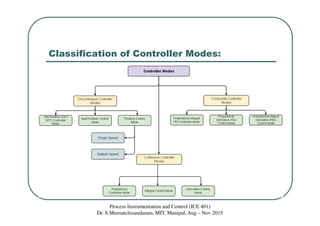
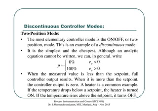
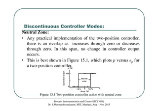
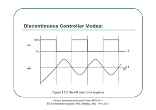
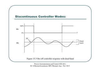
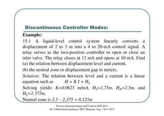
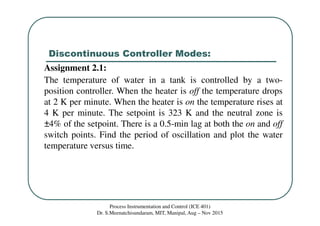
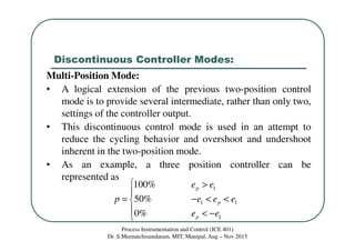
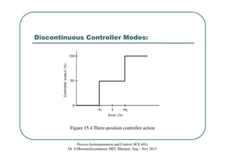
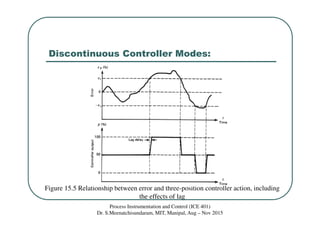

The document discusses various types of controllers used in process control systems. It describes two-position or on-off controllers that have two output states of fully on or fully off. These controllers can exhibit cycling behavior as the process variable oscillates around the setpoint. Multi-position controllers are also covered, which have more than two output levels to help reduce cycling. The document provides examples of how different controller types respond based on the error between the measured process variable and desired setpoint.